EP0727247A1 - Process for purifying gases with water - Google Patents
Process for purifying gases with water Download PDFInfo
- Publication number
- EP0727247A1 EP0727247A1 EP96101973A EP96101973A EP0727247A1 EP 0727247 A1 EP0727247 A1 EP 0727247A1 EP 96101973 A EP96101973 A EP 96101973A EP 96101973 A EP96101973 A EP 96101973A EP 0727247 A1 EP0727247 A1 EP 0727247A1
- Authority
- EP
- European Patent Office
- Prior art keywords
- exhaust gas
- washing
- stage
- zone
- gas
- Prior art date
- Legal status (The legal status is an assumption and is not a legal conclusion. Google has not performed a legal analysis and makes no representation as to the accuracy of the status listed.)
- Granted
Links
Images
Classifications
-
- B—PERFORMING OPERATIONS; TRANSPORTING
- B01—PHYSICAL OR CHEMICAL PROCESSES OR APPARATUS IN GENERAL
- B01D—SEPARATION
- B01D47/00—Separating dispersed particles from gases, air or vapours by liquid as separating agent
- B01D47/12—Washers with plural different washing sections
Definitions
- the invention relates to a method for removing dust and aerosols from an exhaust gas, which is brought into contact with a washing liquid consisting primarily of water in at least two washing stages, fresh water and / or a washing liquid containing fresh water being introduced into the exhaust gas in the last washing stage sprayed into it and the exhaust gas in the penultimate washing stage is brought into contact with a circulated aqueous salt solution which contains substances brought in by the exhaust gas.
- a washing liquid consisting primarily of water in at least two washing stages, fresh water and / or a washing liquid containing fresh water being introduced into the exhaust gas in the last washing stage sprayed into it and the exhaust gas in the penultimate washing stage is brought into contact with a circulated aqueous salt solution which contains substances brought in by the exhaust gas.
- the object of the invention is to achieve a high degree of purification when working with at least two washing stages and to be able to separate not only dust and aerosols, but also gaseous components, in particular HCl and HF, from the exhaust gas as well as possible. At the same time, the amount of waste water generated should be minimized.
- the object is achieved in that the exhaust gas in the penultimate scrubbing stage at temperatures in the range from 30 to 150 ° C. is passed through a scrubbing zone, to which aqueous salt solution which is circulated is fed, the amount of which is introduced into the scrubbing zone passed solution per Nm 3 of exhaust gas that flows through the washing zone, 0.1 to 10 liters, that the exhaust gas coming from the washing zone has a temperature in the range from 30 to 80 ° C, is 90 to 100% saturated with water vapor and has a maximum of 50% by weight of the dust content that the exhaust gas has when entering the penultimate scrubbing stage, and that the exhaust gas is passed through a gas-permeable, turbulence-generating layer in the last washing stage.
- the exhaust gas to be cleaned can e.g. is a flue gas from the combustion of fossil fuels or their processing residues or an exhaust gas from a chemical plant. Values of water vapor saturation are always related to the saturation of the exhaust gas with pure water.
- the exhaust gas in the penultimate scrubbing stage is treated intensively with the circulating aqueous salt solution, the cleaning action of this salt solution being used well.
- the salt content of this solution is quite high and can be up to about 20% by weight. As a result, there is little waste water.
- the scrubbing zone of the penultimate and / or the last scrubbing stage can have a packing layer through which the exhaust gas is passed, but this is not necessary in all cases. The saturation of the exhaust gas with water vapor is improved by at least one packing layer, which results in improved cleaning performance.
- the last washing stage which can also be referred to as a fine cleaning stage, then primarily serves not only to wash out dust and aerosols from the exhaust gas, but also to remove residues of the gaseous constituents HCl and HF and in particular SO 3 aerosols.
- Some of the SO 3 forms sulfuric acid aerosol in the penultimate washing stage, which cannot be separated off in a simple manner.
- the separation of fine dust particles with grain sizes below 3 ⁇ m and in particular below 1 ⁇ m is also known to be difficult.
- the used washing liquid obtained in the last washing stage into a storage container inside or outside the washing stage, to supply fresh water to the storage container and to spray washing liquid from the storage container into the last washing stage.
- a partial flow of the liquid is passed into the penultimate washing stage.
- the salt content of the washing liquid supplied to the last washing stage can be easily regulated.
- the last Washing stage per Nm 3 of exhaust gas sprayed 0.05 to 2 liters of washing liquid into the exhaust gas.
- the fresh water to be used should be as free of alkaline earth metal and low in salt as possible so that it has an electrical conductivity of at most 100 ⁇ S / cm.
- the saline solution circulating in the penultimate washing stage usually consists of water and the substances absorbed from the exhaust gas.
- the pH of the circulating saline solution is usually below 5 and preferably at most 3. If necessary, chemicals can be added to adjust the pH.
- the exhaust gas If the exhaust gas is delivered too hot, it can be passed through an indirect heat exchanger before the washing stages, the condensate formed can be drawn off and it can first be led into the spray zone of the penultimate washing stage at temperatures of 80 to 180 ° C.
- the exhaust gas first enters the penultimate scrubbing stage, which is also referred to below as the first scrubbing stage.
- the exhaust gas is then cleaned in the second scrubbing stage, which is the last scrubbing stage from which the treated exhaust gas is extracted.
- the exhaust gas can then be supplied, for example, to a desulfurization device known per se for removing SO 2 .
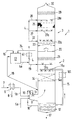
- the drawing shows a washing tower (1) with two washing stages (2) and (3) in a schematic representation.
- pumps in the pipes have been omitted.
- the exhaust gas to be cleaned is introduced in line (5a) or alternatively comes from line (5b).
- the line (5b) is preceded by an indirect heat exchanger (6), to which hot exhaust gas, for example flue gas, is fed through the line (7).
- the heat exchanger (6) is cooled to temperatures in the range from 80 to 180 ° C., condensate being able to form, which is drawn off in the line (8).
- the temperatures in the line (5a) are usually in the range from 100 to 250 ° C. or even higher in individual cases.
- the exhaust gas to be treated is first passed through a spray zone (9), it being sprayed with saline solution which comes out of the line (10) and exits through one or more nozzles (11).
- the saline solution is used washing liquid, which is collected in the sump (12) of the washing tower (1).
- the raw gas is primarily enriched with water vapor and is also cooled to such an extent that it enters the washing zone (14) in the first washing stage (2) when it flows upwards at 40 to 80 ° C.
- Saline solution from the sump (12) is fed through the line (15) by means of a pump (not shown) to the distributor line (15a) and sprayed from there into the washing zone (14).
- the washing zone (14) can contain a liquid-permeable packing layer (14a) indicated by dashed lines or one or more floors, but this is not absolutely necessary.
- the saline solution trickles down through the packing layer, whereby an intensive direct contact with the upward flowing flue gas is achieved.
- dust, gaseous components, in particular HCl and HF, and some of the aerosols, in particular sulfuric acid aerosol are absorbed by the salt solution in the washing zone (14). Sulfuric acid aerosol is generated in the indirect heat exchanger (6), in the spray zone (9) and in the washing zone (14).
- the saline solution flows down into the sump (12) and is largely recycled through line (15).
- the line (15) can additionally be provided with a cooler (161), indicated by dashed lines, in which the saline solution is cooled indirectly.
- Part of the salt solution containing solids is removed from the washing tower through line (17), ensuring that the amount of liquid drawn off is as small as possible.
- the waste water from line (17) is fed to a treatment plant, not shown.
- fresh water can be added at any point or, as shown in the drawing, liquid containing fresh water can be supplied through line (18) or (19).
- the amount of liquid passed through the distributor (15a) into the washing zone (14) is in the range from 0.1 to 10 l / Nm 3 of exhaust gas which flows through the washing zone (14).
- the amount of liquid conveyed through line (15) per unit of time is usually about 10 times greater than the amount of liquid flowing through line (10).
- the exhaust gas Before the exhaust gas leaves the first washing stage (2) and enters the last washing stage (3) through the gas-permeable, liquid-tight floor (20), the exhaust gas still flows through a droplet separator (21).
- the droplet separator (21) ensures that liquid containing contaminants is largely separated from the exhaust gas.
- One method variant consists in spraying fresh water or low-salt washing liquid from the line (19) through the distributor (19a) below the droplet separator (21) into the exhaust gas. This advantageously increases the saturation of the exhaust gas with water vapor, At the same time, solid deposits are washed off in the separator (21).
- the exhaust gas flowing up through the bottom (20) has a temperature in the range from 30 to 80 ° C. and is 90 to 100% saturated with water vapor.
- its dust content is only a maximum of 50% by weight of the dust content which the exhaust gas coming from the spray zone (9) has when it enters the washing zone (14).
- the exhaust gas flowing upward is first intensively mixed with washing liquid containing fresh water, which emerges from the distributor (22a).
- the washing liquid is fed through the line (22), which branches off from the distributor line (4).
- the washing liquid comes from the storage container (13) and the connecting line (4a).
- Used washing liquid that collects on the floor (20) is led in line (24) to the storage container (13), which also has a fresh water supply line (16).
- part of the liquid of the container (13) can be fed through line (18) to the liquid supply in the sump (12).
- the solids and salt content in the liquid in the distributor line (4) can thus be kept low and the cleaning performance can be improved.
- washing liquid in line (4) may be expedient to pass the washing liquid in line (4) through a heat exchanger (41) shown in broken lines in order to heat it up.
- a heat exchanger (41) shown in broken lines in order to heat it up.
- Already heating by 1 to 10 ° C noticeably improves water vapor saturation in the last washing stage (3) and can bring about the desired supersaturation.
- the liquid is sprayed upwards through nozzles and sprayed into the exhaust gas, which also flows upwards.
- the nozzles of the distributor (22a) can be designed in such a way that, in addition to the liquid, air or water vapor can also be let out at high pressure in order to achieve a mist-like liquid distribution.
- the filler layer (23) is particularly recommended if the filler layer (14a) is dispensed with, but both layers can also be used.
- the exhaust gas enters from below into a gas-permeable, turbulence-generating layer (25).
- This layer (25) can be designed in various ways, for example it can be a packing layer or a knitted package, and gas-permeable bottoms are also possible here.
- the layer (25) serves to agglomerate fog particles and aerosols and at the same time to separate them. Drops of liquid formed in the layer (25) fall down and collect on the floor (20), where they are drawn off through the line (24).
- fresh water can also be supplied to the respective distributor through lines (28) and (27).
- the upward flowing flue gas coming from the agglomeration layer (25) is expediently passed through a droplet separator (29), in which the remaining separation of agglomerated fog particles and aerosols takes place before it leaves the washing tower (1) through the outlet (30).
- the gas leaving the scrubbing tower (1) can be fed to a desulfurization device, not shown, which will primarily serve to remove SO 2 .
- One possibility is to connect the outlet (30) to the heat exchanger (6) and to use the relatively cold gas as a cooling medium in the indirect heat exchanger (6).
- a washing tower (1) as shown in the drawing, with two washing zones (2) and (3) and with a packing layer (14a) in the washing zone (14) produces 950 Nm 3 of flue gas per hour from the combustion of heavy oil through the line (5a) fed.
- the reservoir (13) is located differently from the drawing on the floor (20), the lines (19), (27) and (28) with the distributors (19a), (27a) and (28a), and the are missing Radiator (161).
- the flue gas in line (5a) contains 8.5% by volume of water vapor and 5.8% by volume of O 2 ; it enters the spray zone (9) at 175 ° C. and a pressure of 1045 mbar.
- the amounts of liquid are as follows: management 10th 15 22 16 17th 18th Quantity (kg / h) 200 14200 280 66 5 65
- the flue gas coming from the spray zone (9) and flowing to the washing zone (14) has a temperature of 58 ° C and is 92% saturated with water vapor.
- the temperature of the flue gas is 56 ° C and the water vapor saturation is 98%.
- the packing layer (23) was omitted.
- the distributor (22a) is a high-pressure nozzle which sprays the washing liquid in a mist-like manner. This results in complete saturation in the flue gas with water vapor and locally also a slight oversaturation, as a result of which the aerosol particles grow by absorbing water.
- In the Layer (25) is a knitted package made of plastic.
- the solids are primarily carbon and the heavy metals are primarily vanadium and nickel.
Landscapes
- Chemical & Material Sciences (AREA)
- Chemical Kinetics & Catalysis (AREA)
- Treating Waste Gases (AREA)
- Gas Separation By Absorption (AREA)
- Separation Of Particles Using Liquids (AREA)
Abstract
Description
Die Erfindung betrifft ein Verfahren zum Entfernen von Staub und Aerosolen aus einem Abgas, welches man in mindestens zwei Waschstufen mit einer vor allem aus Wasser bestehenden Waschflüssigkeit in Kontakt bringt, wobei man in der letzten Waschstufe Frischwasser und/oder eine Frischwasser enthaltende Waschflüssigkeit in das Abgas hinein versprüht und wobei man das Abgas in der vorletzten Waschstufe mit einer im Kreislauf geführten wäßrigen Salzlösung in Kontakt bringt, welche durch das Abgas herangeführte Stoffe enthält.The invention relates to a method for removing dust and aerosols from an exhaust gas, which is brought into contact with a washing liquid consisting primarily of water in at least two washing stages, fresh water and / or a washing liquid containing fresh water being introduced into the exhaust gas in the last washing stage sprayed into it and the exhaust gas in the penultimate washing stage is brought into contact with a circulated aqueous salt solution which contains substances brought in by the exhaust gas.
Ein solches Verfahren ist aus DE-C-41 13 108 bekannt. Ein einstufiges Verfahren ist in EP-A-0 516 205 beschrieben.Such a method is known from DE-C-41 13 108. A one-step process is described in EP-A-0 516 205.
Der Erfindung liegt die Aufgabe zugrunde, beim Arbeiten mit mindestens zwei Waschstufen einen hohen Reinigungsgrad zu erreichen und nicht nur Staub und Aerosole, sondern auch gasförmige Bestandteile, insbesondere HCl und HF, möglichst gut aus dem Abgas abscheiden zu können. Gleichzeitig soll die Menge an anfallendem Abwasser minimiert werden.The object of the invention is to achieve a high degree of purification when working with at least two washing stages and to be able to separate not only dust and aerosols, but also gaseous components, in particular HCl and HF, from the exhaust gas as well as possible. At the same time, the amount of waste water generated should be minimized.
Beim eingangs genannten Verfahren wird die Aufgabe erfindungsgemäß dadurch gelöst, daß man das Abgas in der vorletzten Waschstufe mit Temperaturen im Bereich von 30 bis 150°C durch eine Waschzone leitet, welcher man im Kreislauf geführte wäßrige Salzlösung zuführt, wobei die Menge der in die Waschzone geleiteten Lösung pro Nm3 Abgas, welches durch die Waschzone strömt, 0,1 bis 10 Liter beträgt, daß das aus der Waschzone kommende Abgas
eine Temperatur im Bereich von 30 bis 80°C hat,
zu 90 bis 100 % mit Wasserdampf gesättigt ist und
höchstens 50 Gew.-% des Staubgehalts aufweist, den das Abgas beim Eintritt in die vorletzte Waschstufe hat,
und daß man das Abgas in der letzten Waschstufe durch eine gasdurchlässige, Turbulenz erzeugende Schicht leitet.In the process mentioned in the introduction, the object is achieved in that the exhaust gas in the penultimate scrubbing stage at temperatures in the range from 30 to 150 ° C. is passed through a scrubbing zone, to which aqueous salt solution which is circulated is fed, the amount of which is introduced into the scrubbing zone passed solution per Nm 3 of exhaust gas that flows through the washing zone, 0.1 to 10 liters, that the exhaust gas coming from the washing zone
has a temperature in the range from 30 to 80 ° C,
is 90 to 100% saturated with water vapor and
has a maximum of 50% by weight of the dust content that the exhaust gas has when entering the penultimate scrubbing stage,
and that the exhaust gas is passed through a gas-permeable, turbulence-generating layer in the last washing stage.
Beim zu reinigenden Abgas kann es sich z.B. um ein Rauchgas aus der Verbrennung fossiler Brennstoffe oder ihrer Verarbeitungsrückstände oder aber um ein Abgas aus einer Chemieanlage handeln. Werte der Wasserdampf-Sättigung werden hier stets bezogen auf die Sättigung des Abgases mit reinem Wasser.The exhaust gas to be cleaned can e.g. is a flue gas from the combustion of fossil fuels or their processing residues or an exhaust gas from a chemical plant. Values of water vapor saturation are always related to the saturation of the exhaust gas with pure water.
Beim Verfahren der Erfindung wird das Abgas in der vorletzten Waschstufe intensiv mit der im Kreislauf geführten wäßrigen Salzlösung behandelt, wobei die Reinigungswirkung dieser Salzlösung gut genutzt wird. Der Salzgehalt dieser Lösung ist ziemlich hoch und kann bis etwa 20 Gew.-% betragen. Dadurch fällt nur wenig Abwasser an. Die Waschzone der vorletzten und/oder der letzten Waschstufe kann eine Füllkörperschicht aufweisen, durch die das Abgas geleitet wird, doch ist dies nicht in allen Fällen notwendig. Durch mindestens eine Füllkörperschicht wird die Sättigung des Abgases mit Wasserdampf verbessert, was eine verbesserte Reinigungsleistung zur Folge hat.In the process of the invention, the exhaust gas in the penultimate scrubbing stage is treated intensively with the circulating aqueous salt solution, the cleaning action of this salt solution being used well. The salt content of this solution is quite high and can be up to about 20% by weight. As a result, there is little waste water. The scrubbing zone of the penultimate and / or the last scrubbing stage can have a packing layer through which the exhaust gas is passed, but this is not necessary in all cases. The saturation of the exhaust gas with water vapor is improved by at least one packing layer, which results in improved cleaning performance.
Die letzte Waschstufe, die auch als Feinreinigungsstufe bezeichnet werden kann, dient dann vor allem dazu, nicht nur Staub und Aerosole aus dem Abgas auszuwaschen, sondern auch Reste der gasförmigen Bestandteile HCl und HF sowie insbesondere SO3-Aerosole zu entfernen. Das SO3 bildet teilweise schon in der vorletzten Waschstufe Schwefelsäure-Aerosol, welches sich nicht auf einfache Weise abscheiden läßt. Ebenso ist die Abscheidung von Feinststaubpartikeln mit Korngrößen unter 3 µm und insbesondere unter 1 µm bekanntermaßen schwierig. Um hier zu guten Ergebnissen zu gelangen, wird dafür gesorgt, daß das Abgas mit relativ niedriger Temperatur im Bereich von 30 bis 80°C und vorzugsweise höchstens 70°C in die letzte Waschstufe eintritt und dabei mit Wasserdampf weitgehend gesättigt ist. Gleichzeitig wird bereits in der vorletzten Waschstufe für die zu entfernenden Stoffe eine hohe Reinigungsleistung erbracht, wodurch die letzte Waschstufe entlastet ist. Auch wenn die Zahl der Waschstufen nicht begrenzt ist, wird man aus Kostengründen bemüht sein, mit zwei oder höchstens drei Waschstufen auszukommen.The last washing stage, which can also be referred to as a fine cleaning stage, then primarily serves not only to wash out dust and aerosols from the exhaust gas, but also to remove residues of the gaseous constituents HCl and HF and in particular SO 3 aerosols. Some of the SO 3 forms sulfuric acid aerosol in the penultimate washing stage, which cannot be separated off in a simple manner. The separation of fine dust particles with grain sizes below 3 µm and in particular below 1 µm is also known to be difficult. In order to achieve good results here, it is ensured that the exhaust gas enters the last washing stage at a relatively low temperature in the range from 30 to 80 ° C. and preferably at most 70 ° C. and is largely saturated with water vapor. At the same time, a high cleaning performance is already provided in the penultimate washing stage for the substances to be removed, which means that the last washing stage is relieved. Even if the number of washing stages is not limited, efforts will be made to manage with two or at most three washing stages for cost reasons.
Es ist zweckmäßig, die in der letzten Waschstufe anfallende, gebrauchte Waschflüssigkeit in einen Vorratsbehälter innerhalb oder außerhalb der Waschstufe zu leiten, dem Vorratsbehälter Frischwasser zuzuführen und Waschflüssigkeit aus dem Vorratsbehälter in die letzte Waschstufe hinein zu versprühen. Zusätzlich wird ein Teilstrom der Flüssigkeit in die vorletzte Waschstufe geleitet. Auf diese Weise kann der Salzgehalt der der letzten Waschstufe zugeführten Waschflüssigkeit leicht geregelt werden. Üblicherweise wird in der letzten Waschstufe pro Nm3 Abgas 0,05 bis 2 Liter Waschflüssigkeit in das Abgas hinein versprüht. Es kann zweckmäßig sein, die Waschflüssigkeit vor dem Versprühen anzuwärmen, z.B. um 1 bis 10°C, um die Wasserdampf-Sättigung in der letzten Waschstufe zu erhöhen und um möglichst Übersättigung zu erreichen. Das zu verwendende Frischwasser sollte möglichst erdalkalifrei und salzarm sein, so daß es eine elektrische Leitfähigkeit von höchstens 100 µS/cm hat.It is expedient to pass the used washing liquid obtained in the last washing stage into a storage container inside or outside the washing stage, to supply fresh water to the storage container and to spray washing liquid from the storage container into the last washing stage. In addition, a partial flow of the liquid is passed into the penultimate washing stage. In this way, the salt content of the washing liquid supplied to the last washing stage can be easily regulated. Usually in the last Washing stage per Nm 3 of exhaust gas sprayed 0.05 to 2 liters of washing liquid into the exhaust gas. It may be expedient to warm the washing liquid before spraying, for example by 1 to 10 ° C., in order to increase the water vapor saturation in the last washing stage and to achieve supersaturation as far as possible. The fresh water to be used should be as free of alkaline earth metal and low in salt as possible so that it has an electrical conductivity of at most 100 µS / cm.
Es empfiehlt sich, das Abgas mit einer Temperatur von höchstens 180°C der vorletzten Waschstufe zuzuführen. Es kann zweckmäßig sein, das Abgas vor dem Eintritt in die Waschzone in einer Sprühzone mit der im Kreislauf geführten wäßrigen Salzlösung in Kontakt zu bringen und es dadurch sowohl mit Wasserdampf anzureichern als auch zu kühlen. Durch diese Maßnahme wird die Reinigungswirkung der Waschzone unterstützt. Die in der vorletzten Waschstufe umlaufende Salzlösung besteht üblicherweise aus Wasser und den aus dem Abgas aufgenommenen Stoffen. Der pH-Wert der im Kreislauf geführten Salzlösung liegt üblicherweise unterhalb von 5 und vorzugsweise bei höchstens 3. Bei Bedarf können Chemikalien zur pH-Wert-Einstellung zugegeben werden.It is advisable to feed the flue gas to the penultimate washing stage at a temperature of at most 180 ° C. It may be expedient to bring the exhaust gas into contact with the circulated aqueous salt solution in a spray zone before entering the washing zone, thereby enriching it with water vapor and also cooling it. This measure supports the cleaning effect of the washing zone. The saline solution circulating in the penultimate washing stage usually consists of water and the substances absorbed from the exhaust gas. The pH of the circulating saline solution is usually below 5 and preferably at most 3. If necessary, chemicals can be added to adjust the pH.
Wenn das Abgas zu heiß angeliefert wird, kann man es vor den Waschstufen durch einen indirekten Wärmeaustauscher leiten, gebildetes Kondensat abziehen und es mit Temperaturen von 80 bis 180°C zunächst in die Sprühzone der vorletzten Waschstufe führen.If the exhaust gas is delivered too hot, it can be passed through an indirect heat exchanger before the washing stages, the condensate formed can be drawn off and it can first be led into the spray zone of the penultimate washing stage at temperatures of 80 to 180 ° C.
Für das erfindungsgemäße Verfahren ist es im allgemeinen ausreichend, mit zwei Waschstufen zu arbeiten. Hierbei tritt das Abgas zunächst in die vorletzte Waschstufe ein, die nachfolgend auch als erste Waschstufe bezeichnet wird. Die Feinreinigung des Abgases erfolgt dann in der zweiten Waschstufe, bei der es sich um die letzte Waschstufe handelt, aus welcher man das behandelte Abgas abzieht. Das Abgas kann anschließend z.B. einer an sich bekannten Entschwefelungseinrichtung zur Entfernung von SO2 zugeführt werden.For the process according to the invention it is generally sufficient to work with two washing stages. Here, the exhaust gas first enters the penultimate scrubbing stage, which is also referred to below as the first scrubbing stage. The exhaust gas is then cleaned in the second scrubbing stage, which is the last scrubbing stage from which the treated exhaust gas is extracted. The exhaust gas can then be supplied, for example, to a desulfurization device known per se for removing SO 2 .
Ausgestaltungsmöglichkeiten des Verfahrens werden mit Hilfe der Zeichnung erläutert.Design options of the method are explained with the aid of the drawing.
Die Zeichnung zeigt in schematischer Darstellung einen Waschturm (1) mit zwei Waschstufen (2) und (3). Der besseren Übersichtlichkeit wegen wurden Pumpen in den Leitungen weggelassen.The drawing shows a washing tower (1) with two washing stages (2) and (3) in a schematic representation. For the sake of clarity, pumps in the pipes have been omitted.
Das zu reinigende Abgas wird in der Leitung (5a) herangeführt oder kommt alternativ aus der Leitung (5b). Der Leitung (5b) ist ein indirekter Wärmeaustauscher (6) vorgeschaltet, dem man durch die Leitung (7) heißes Abgas, z.B. Rauchgas, zuführt. Im Wärmeaustauscher (6) erfolgt eine Kühlung auf Temperaturen im Bereich von 80 bis 180°C, wobei Kondensat entstehen kann, welches man in der Leitung (8) abzieht. Üblicherweise liegen die Temperaturen in der Leitung (5a) im Bereich von 100 bis 250°C oder in Einzelfällen noch höher.The exhaust gas to be cleaned is introduced in line (5a) or alternatively comes from line (5b). The line (5b) is preceded by an indirect heat exchanger (6), to which hot exhaust gas, for example flue gas, is fed through the line (7). The heat exchanger (6) is cooled to temperatures in the range from 80 to 180 ° C., condensate being able to form, which is drawn off in the line (8). The temperatures in the line (5a) are usually in the range from 100 to 250 ° C. or even higher in individual cases.
Zunächst leitet man das zu behandelnde Abgas durch eine Sprühzone (9), wobei es mit Salzlösung besprüht wird, die aus der Leitung (10) kommt und über eine oder mehrere Düsen (11) austritt. Bei der Salzlösung handelt es sich um gebrauchte Waschflüssigkeit, die im Sumpf (12) des Waschturms (1) gesammelt wird. In der Sprühzone (9) wird das Rohgas vor allem mit Wasserdampf angereichert und dabei auch so weit gekühlt, daß es in der ersten Waschstufe (2) beim Aufwärtsströmen mit 40 bis 80°C in die Waschzone (14) eintritt. Salzlösung aus dem Sumpf (12) wird durch die Leitung (15) mittels einer nicht dargestellten Pumpe zur Verteilerleitung (15a) geführt und von hier in die Waschzone (14) hinein versprüht. Die Waschzone (14) kann eine gestrichelt angedeutete flüssigkeitsdurchlässige Füllkörperschicht (14a) oder einen oder mehrere Böden enthalten, doch ist dies nicht unbedingt erforderlich. In diesem Fall rieselt die Salzlösung durch die Füllkörperschicht abwärts, wobei ein intensiver direkter Kontakt mit dem aufwärts strömenden Rauchgas erreicht wird. Mit oder ohne Füllkörperschicht werden in der Waschzone (14) Staub, gasförmige Bestandteile, insbesondere HCl und HF, sowie ein Teil der Aerosole, insbesondere Schwefelsäure-Aerosol, von der Salzlösung aufgenommen. Schwefelsäure-Aerosol entsteht im indirekten Wärmeaustauscher (6), in der Sprühzone (9) und in der Waschzone (14).The exhaust gas to be treated is first passed through a spray zone (9), it being sprayed with saline solution which comes out of the line (10) and exits through one or more nozzles (11). The saline solution is used washing liquid, which is collected in the sump (12) of the washing tower (1). In the spray zone (9), the raw gas is primarily enriched with water vapor and is also cooled to such an extent that it enters the washing zone (14) in the first washing stage (2) when it flows upwards at 40 to 80 ° C. Saline solution from the sump (12) is fed through the line (15) by means of a pump (not shown) to the distributor line (15a) and sprayed from there into the washing zone (14). The washing zone (14) can contain a liquid-permeable packing layer (14a) indicated by dashed lines or one or more floors, but this is not absolutely necessary. In this case, the saline solution trickles down through the packing layer, whereby an intensive direct contact with the upward flowing flue gas is achieved. With or without a packing layer, dust, gaseous components, in particular HCl and HF, and some of the aerosols, in particular sulfuric acid aerosol, are absorbed by the salt solution in the washing zone (14). Sulfuric acid aerosol is generated in the indirect heat exchanger (6), in the spray zone (9) and in the washing zone (14).
Die Salzlösung fließt nach unten in den Sumpf (12) ab und wird größtenteils durch die Leitung (15) im Kreislauf zurückgeführt. Die Leitung (15) kann zusätzlich mit einem gestrichelt angedeuteten Kühler (161) versehen sein, in welchem die Salzlösung indirekt gekühlt wird. Ein Teil der feststoffhaltigen Salzlösung wird durch die Leitung (17) aus dem Waschturm entfernt, wobei man dafür sorgt, daß die abgezogene Flüssigkeitsmenge möglichst klein ist. Das Abwasser der Leitung (17) wird einer nicht dargestellten Aufbereitungsanlage zugeführt. Um die in der ersten Waschzone (2) vorhandene Flüssigkeitsmenge etwa konstant zu halten, kann man an einer beliebigen Stelle Frischwasser zugeben oder aber, wie in der Zeichnung dargestellt, durch die Leitung (18) oder (19) Frischwasser enthaltende Flüssigkeit zuführen.The saline solution flows down into the sump (12) and is largely recycled through line (15). The line (15) can additionally be provided with a cooler (161), indicated by dashed lines, in which the saline solution is cooled indirectly. Part of the salt solution containing solids is removed from the washing tower through line (17), ensuring that the amount of liquid drawn off is as small as possible. The waste water from line (17) is fed to a treatment plant, not shown. In order to keep the amount of liquid present in the first washing zone (2) approximately constant, fresh water can be added at any point or, as shown in the drawing, liquid containing fresh water can be supplied through line (18) or (19).
Die durch den Verteiler (15a) in die Waschzone (14) geleitete Flüssigkeitsmenge liegt im Bereich von 0,1 bis 10 l/Nm3 Abgas, welches durch die Waschzone (14) strömt. Die pro Zeiteinheit durch die Leitung (15) geförderte Flüssigkeitsmenge ist üblicherweise etwa 10mal größer als die durch die Leitung (10) strömende Flüssigkeitsmenge.The amount of liquid passed through the distributor (15a) into the washing zone (14) is in the range from 0.1 to 10 l / Nm 3 of exhaust gas which flows through the washing zone (14). The amount of liquid conveyed through line (15) per unit of time is usually about 10 times greater than the amount of liquid flowing through line (10).
Bevor das Abgas die erste Waschstufe (2) verläßt und durch den gasdurchlässigen, flüssigkeitsdichten Boden (20) in die letzte Waschstufe (3) eintritt, strömt das Abgas noch durch einen Tropfenabscheider (21). Der Tropfenabscheider (21) sorgt dafür, daß Verunreinigungen enthaltende Flüssigkeit aus dem Abgas weitgehend abgetrennt wird. Eine Verfahrensvariante besteht darin, Frischwasser oder aber salzarme Waschflüssigkeit aus der Leitung (19) durch den Verteiler (19a) unterhalb des Tropfenabscheiders (21) in das Abgas einzusprühen. Dadurch wird die Sättigung des Abgases mit Wasserdampf in vorteilhafter Weise erhöht, gleichzeitig werden Feststoff-Ablagerungen im Abscheider (21) abgewaschen.Before the exhaust gas leaves the first washing stage (2) and enters the last washing stage (3) through the gas-permeable, liquid-tight floor (20), the exhaust gas still flows through a droplet separator (21). The droplet separator (21) ensures that liquid containing contaminants is largely separated from the exhaust gas. One method variant consists in spraying fresh water or low-salt washing liquid from the line (19) through the distributor (19a) below the droplet separator (21) into the exhaust gas. This advantageously increases the saturation of the exhaust gas with water vapor, At the same time, solid deposits are washed off in the separator (21).
Das durch den Boden (20) aufwärts strömende Abgas weist eine Temperatur im Bereich von 30 bis 80°C auf und es ist zu 90 bis 100 % mit Wasserdampf gesättigt. Gleichzeitig beträgt sein Staubgehalt nur noch höchstens 50 Gew.-% des Staubgehaltes, den das von der Sprühzone (9) kommende Abgas beim Eintritt in die Waschzone (14) aufweist.The exhaust gas flowing up through the bottom (20) has a temperature in the range from 30 to 80 ° C. and is 90 to 100% saturated with water vapor. At the same time, its dust content is only a maximum of 50% by weight of the dust content which the exhaust gas coming from the spray zone (9) has when it enters the washing zone (14).
In der zweiten und gleichzeitig letzten Waschstufe (3) wird das aufwärts strömende Abgas zunächst intensiv mit Frischwasser enthaltender Waschflüssigkeit durchsetzt, welche aus dem Verteiler (22a) austritt. Die Waschflüssigkeit wird durch die Leitung (22) zugespeist, welche von der Verteilerleitung (4) abzweigt. Die Waschflüssigkeit kommt aus dem Vorratsbehälter (13) und der Verbindungsleitung (4a). Gebrauchte Waschflüssigkeit, die sich auf dem Boden (20) sammelt, wird in der Leitung (24) zum Vorratsbehälter (13) geführt, der auch eine Frischwasser-Zuleitung (16) besitzt. Wie bereits beschrieben, kann man einen Teil der Flüssigkeit des Behälters (13) durch die Leitung (18) dem Flüssigkeitsvorrat im Sumpf (12) zuführen. Damit läßt sich der Feststoff- und Salzgehalt in der Flüssigkeit der Verteilerleitung (4) niedrig halten und die Reinigungsleistung verbessern.In the second and at the same time last washing stage (3), the exhaust gas flowing upward is first intensively mixed with washing liquid containing fresh water, which emerges from the distributor (22a). The washing liquid is fed through the line (22), which branches off from the distributor line (4). The washing liquid comes from the storage container (13) and the connecting line (4a). Used washing liquid that collects on the floor (20) is led in line (24) to the storage container (13), which also has a fresh water supply line (16). As already described, part of the liquid of the container (13) can be fed through line (18) to the liquid supply in the sump (12). The solids and salt content in the liquid in the distributor line (4) can thus be kept low and the cleaning performance can be improved.
Es kann zweckmäßig sein, die Waschflüssigkeit in der Leitung (4) durch einen gestrichelt eingezeichneten Wärmeaustauscher (41) zu führen, um sie anzuwärmen. Bereits eine Erwärmung um 1 bis 10°C verbessert die Wasserdampf-Sättigung in der letzten Waschstufe (3) spürbar und kann die erwünschte Übersättigung herbeiführen.It may be expedient to pass the washing liquid in line (4) through a heat exchanger (41) shown in broken lines in order to heat it up. Already heating by 1 to 10 ° C noticeably improves water vapor saturation in the last washing stage (3) and can bring about the desired supersaturation.
Durch den Verteiler (22a) wird die Flüssigkeit durch Düsen aufwärts gerichtet nebelartig fein versprüht in das ebenfalls aufwärts strömende Abgas eingetragen. In bekannter Weise können die Düsen des Verteilers (22a) so ausgebildet sein, daß man neben der Flüssigkeit zusätzlich Luft oder Wasserdampf mit hohem Druck austreten läßt, um eine nebelähnliche Flüssigkeitsverteilung zu erreichen.Through the distributor (22a) the liquid is sprayed upwards through nozzles and sprayed into the exhaust gas, which also flows upwards. In a known manner, the nozzles of the distributor (22a) can be designed in such a way that, in addition to the liquid, air or water vapor can also be let out at high pressure in order to achieve a mist-like liquid distribution.
Es kann zweckmäßig sein, das in die letzte Waschstufe (3) eintretende, Wasserdampf mit sich führende Abgas zunächst durch eine Füllkörperschicht (23) zu leiten. Möglicherweise verbessert sich dadurch die Verteilung des Wasserdampfs im Abgas und die Sättigung des Abgases mit Wasserdampf. Insbesondere dann, wenn man auf die Füllkörperschicht (14a) verzichtet, wird sich die Füllkörperschicht (23) empfehlen, doch können auch beide Schichten Anwendung finden.It may be expedient to first pass the exhaust gas which is entering the last washing stage (3) and carries exhaust gas through a packing layer (23). This may improve the distribution of water vapor in the exhaust gas and the saturation of the exhaust gas with water vapor. The filler layer (23) is particularly recommended if the filler layer (14a) is dispensed with, but both layers can also be used.
Mit Wasserdampf praktisch gesättigt tritt das Abgas von unten in eine gasdurchlässige, Turbulenz erzeugende Schicht (25) ein. Diese Schicht (25) kann in verschiedener Weise ausgestaltet sein, es kann sich z.B. um eine Füllkörperschicht oder Gestrickpackung handeln, auch sind hier gasdurchlässige Böden möglich. Die Schicht (25) dient der Agglomeration von Nebelteilchen und Aerosolen und gleichzeitig deren Abscheidung. In der Schicht (25) gebildete Flüssigkeitstropfen fallen nach unten und sammeln sich auf dem Boden (20), wo sie durch die Leitung (24) abgezogen werden.Practically saturated with water vapor, the exhaust gas enters from below into a gas-permeable, turbulence-generating layer (25). This layer (25) can be designed in various ways, for example it can be a packing layer or a knitted package, and gas-permeable bottoms are also possible here. The layer (25) serves to agglomerate fog particles and aerosols and at the same time to separate them. Drops of liquid formed in the layer (25) fall down and collect on the floor (20), where they are drawn off through the line (24).
Als Verfahrensalternative kann es zweckmäßig sein, Waschflüssigkeit aus der Leitung (4) durch die Leitung (27) heranzuführen und über den angeschlossenen Verteiler (27a) zusätzlich zu versprühen oder auch Waschflüssigkeit durch die Leitung (28) einem über der Schicht (25) angeordneten Verteiler (28a) zuzuführen und von dort auf die Schicht (25) zu versprühen. Abweichend von der Zeichnung kann man durch die Leitungen (28) und (27) auch Frischwasser dem jeweiligen Verteiler zuführen.As a process alternative, it can be expedient to feed washing liquid from line (4) through line (27) and additionally spray it via the connected distributor (27a) or also washing liquid through line (28) to a distributor arranged above the layer (25) (28a) and spray from there onto the layer (25). Deviating from the drawing, fresh water can also be supplied to the respective distributor through lines (28) and (27).
Das aufwärts strömende, von der Agglomerationsschicht (25) kommende Rauchgas wird zweckmäßigerweise noch durch einen Tropfenabscheider (29) geführt, in welchem die restliche Abscheidung von agglomerierten Nebelteilchen und Aerosolen erfolgt, bevor es den Waschturm (1) durch den Auslaß (30) verläßt. Das den Waschturm (1) verlassende Gas kann einer nicht dargestellten Entschwefelungseinrichtung zugeführt werden, die vor allem dazu dienen wird, SO2 zu entfernen. Eine Möglichkeit besteht darin, den Auslaß (30) mit dem Wärmeaustauscher (6) zu verbinden und das relativ kalte Gas als Kühlmedium im indirekten Wärmeaustauscher (6) zu verwenden.The upward flowing flue gas coming from the agglomeration layer (25) is expediently passed through a droplet separator (29), in which the remaining separation of agglomerated fog particles and aerosols takes place before it leaves the washing tower (1) through the outlet (30). The gas leaving the scrubbing tower (1) can be fed to a desulfurization device, not shown, which will primarily serve to remove SO 2 . One possibility is to connect the outlet (30) to the heat exchanger (6) and to use the relatively cold gas as a cooling medium in the indirect heat exchanger (6).
Einem Waschturm (1), wie in der Zeichnung dargestellt, mit zwei Waschzonen (2) und (3) und mit einer Füllkörperschicht (14a) in der Waschzone (14) werden pro Stunde 950 Nm3 Rauchgas aus der Verbrennung von Schweröl durch die Leitung (5a) zugeführt. Der Vorratsbehälter (13) befindet sich abweichend von der Zeichnung auf dem Boden (20), es fehlen die Leitungen (19), (27) und (28) mit den Verteilern (19a), (27a) und (28a), sowie der Kühler (161). Das Rauchgas der Leitung (5a) enthält 8,5 Vol.-% Wasserdampf und 5,8 Vol.-% O2, es tritt mit 175°C und einem Druck von 1045 mbar in die Sprühzone (9) ein.A washing tower (1), as shown in the drawing, with two washing zones (2) and (3) and with a packing layer (14a) in the washing zone (14) produces 950 Nm 3 of flue gas per hour from the combustion of heavy oil through the line (5a) fed. The reservoir (13) is located differently from the drawing on the floor (20), the lines (19), (27) and (28) with the distributors (19a), (27a) and (28a), and the are missing Radiator (161). The flue gas in line (5a) contains 8.5% by volume of water vapor and 5.8% by volume of O 2 ; it enters the spray zone (9) at 175 ° C. and a pressure of 1045 mbar.
Die Flüssigkeitsmengen sind folgende:
Das aus der Sprühzone (9) kommende, zur Waschzone (14) strömende Rauchgas hat eine Temperatur von 58°C und ist zu 92 % mit Wasserdampf gesättigt. Beim Durchströmen des Bodens (20) liegt die Temperatur des Rauchgases bei 56°C und die Wasserdampf-Sättigung bei 98 %. Die Füllkörperschicht (23) wurde weggelassen. Der Verteiler (22a) ist eine Hochdruckdüse, welche die Waschflüssigkeit nebelartig fein versprüht. Es wird dadurch im Rauchgas eine vollständige Sättigung mit Wasserdampf und lokal auch eine leichte Übersättigung erzielt, wodurch ein Wachsen der Aerosolteilchen durch Wasseraufnahme erreicht wird. Bei der Schicht (25) handelt es sich um eine Gestrickpackung aus Kunststoff.The flue gas coming from the spray zone (9) and flowing to the washing zone (14) has a temperature of 58 ° C and is 92% saturated with water vapor. When flowing through the floor (20), the temperature of the flue gas is 56 ° C and the water vapor saturation is 98%. The packing layer (23) was omitted. The distributor (22a) is a high-pressure nozzle which sprays the washing liquid in a mist-like manner. This results in complete saturation in the flue gas with water vapor and locally also a slight oversaturation, as a result of which the aerosol particles grow by absorbing water. In the Layer (25) is a knitted package made of plastic.
Der Gehalt an Verunreinigungen im Rauchgas - in mg/Nm3 - an verschiedenen Stellen des Waschturms ist in der folgenden Tabelle angegeben:
Die Inhaltsstoffe des Wassers der Leitung (18) sind nachfolgend in Spalte A und die der Leitung (17) in Spalte B angegeben (in g/l):
Bei den Feststoffen handelt es sich vor allem um Kohlenstoff und bei den Schwermetallen vor allem um Vanadium und Nickel.The solids are primarily carbon and the heavy metals are primarily vanadium and nickel.
Claims (11)
eine Temperatur im Bereich von 30 bis 80°C hat,
zu 90 bis 100 % mit Wasserdampf gesättigt ist und
höchstens 50 Gew.-% des Staubgehalts aufweist, den das Abgas beim Eintritt in die vorletzte Waschstufe hat,
und daß man das Abgas in der letzten Waschstufe durch eine gasdurchlässige, Turbulenz erzeugende Schicht leitet.Process for removing dust and aerosols from an exhaust gas, which is brought into contact with a washing liquid consisting primarily of water in at least two washing stages, fresh water and / or a washing liquid containing fresh water being sprayed into the exhaust gas in the last washing stage and wherein the exhaust gas in the penultimate washing stage is brought into contact with a circulating aqueous salt solution which contains substances brought in by the exhaust gas, characterized in that the exhaust gas in the penultimate washing stage is at a temperature in the range from 30 to 150 ° C. through a washing zone conducts, which is fed to circulated aqueous salt solution, the amount of the solution passed into the washing zone per Nm 3 of exhaust gas flowing through the washing zone being 0.1 to 10 liters, that the exhaust gas coming from the washing zone
has a temperature in the range from 30 to 80 ° C,
is 90 to 100% saturated with water vapor and
has a maximum of 50% by weight of the dust content that the exhaust gas has when entering the penultimate scrubbing stage,
and that the exhaust gas is passed through a gas-permeable, turbulence-generating layer in the last washing stage.
Applications Claiming Priority (2)
| Application Number | Priority Date | Filing Date | Title |
|---|---|---|---|
| DE19505231A DE19505231A1 (en) | 1995-02-16 | 1995-02-16 | Process for cleaning gases with water |
| DE19505231 | 1995-02-16 |
Publications (2)
| Publication Number | Publication Date |
|---|---|
| EP0727247A1 true EP0727247A1 (en) | 1996-08-21 |
| EP0727247B1 EP0727247B1 (en) | 1999-06-09 |
Family
ID=7754148
Family Applications (1)
| Application Number | Title | Priority Date | Filing Date |
|---|---|---|---|
| EP96101973A Expired - Lifetime EP0727247B1 (en) | 1995-02-16 | 1996-02-12 | Process for purifying gases with water |
Country Status (5)
| Country | Link |
|---|---|
| US (1) | US5660615A (en) |
| EP (1) | EP0727247B1 (en) |
| JP (1) | JPH08281049A (en) |
| AT (1) | ATE180988T1 (en) |
| DE (2) | DE19505231A1 (en) |
Cited By (3)
| Publication number | Priority date | Publication date | Assignee | Title |
|---|---|---|---|---|
| EP0953373A2 (en) * | 1998-04-20 | 1999-11-03 | Basf Aktiengesellschaft | Process for removal of impurities from a gas stream |
| EP2638942B1 (en) * | 2012-03-15 | 2016-09-21 | Cryostar SAS | Mist separation apparatus |
| CN108434950A (en) * | 2018-03-15 | 2018-08-24 | 东南大学 | A kind of devices and methods therefor of the evaporation of coordinated desulfurization waste water flue and enhancing fine particle and sulfur trioxide removing |
Families Citing this family (23)
| Publication number | Priority date | Publication date | Assignee | Title |
|---|---|---|---|---|
| US5938820A (en) * | 1996-06-27 | 1999-08-17 | Cmi-Schneible Company | Air and gas scrubber using recycled water mixture |
| DE19705897A1 (en) * | 1997-02-15 | 1998-08-27 | Veba Kraftwerke Ruhr | Process for suppressing the formation of sulfuric acid aerosols in exhaust gas cleaning systems |
| WO1999025460A1 (en) * | 1997-11-14 | 1999-05-27 | Bedminster Bioconversion Corporation | Bio-tower |
| US5951743A (en) * | 1997-12-05 | 1999-09-14 | Taiwan Semiconductor Manufacturing Co., Ltd. | Method and apparatus for feeding exhaust gases to a wet scrubber |
| US6312503B1 (en) * | 1999-10-13 | 2001-11-06 | Arteva North America S.A.R.L. | System to quench gasses and remove condensables |
| KR100412999B1 (en) * | 2000-05-30 | 2003-12-31 | 최용석 | Water sprinkle circulation type dust collector |
| TW527221B (en) * | 2000-08-21 | 2003-04-11 | Sumitomo Chemical Co | Method for removing sulfuric acid mist and apparatus for removing the same |
| DE10256388B3 (en) * | 2002-12-02 | 2004-07-29 | Rhodius Gmbh | Ultra-fine filter insert and filter arrangement for separating finely distributed droplets from aerosols |
| DE10305578A1 (en) * | 2003-02-11 | 2004-08-19 | Basf Ag | Method and device for reducing the aerosol-related discharge from a separation column |
| US7025809B2 (en) * | 2003-12-11 | 2006-04-11 | Taiwan Semiconductor Manufacturing Co., Ltd. | Dual-type air purification system |
| US20080185350A1 (en) * | 2007-02-05 | 2008-08-07 | Koch-Glitsch, Lp | Method and apparatus for separating oil sand particulates from a three-phase stream |
| JP2009018290A (en) * | 2007-07-13 | 2009-01-29 | Ebara Corp | Exhaust gas washing device |
| JP4365442B1 (en) * | 2008-05-29 | 2009-11-18 | 株式会社神戸製鋼所 | Coal reforming method |
| US20100119420A1 (en) * | 2008-11-07 | 2010-05-13 | Applied Materials, Inc. | Abatement system having enhanced effluent scrub and moisture control |
| WO2010079598A1 (en) * | 2009-01-08 | 2010-07-15 | 日本山村硝子株式会社 | Facility and method for the treatment of gases which contain alkali metal halides |
| US20130055757A1 (en) * | 2011-09-06 | 2013-03-07 | Chevron U.S.A. | Method and system to prevent carry-over of hydrocarbon mist from an ngl column of an lng plant |
| CN103071371B (en) * | 2011-10-26 | 2014-12-31 | 密西西比国际水务(中国)有限公司 | Treating method and apparatus for active coke regenerated mixed steam |
| JP5805613B2 (en) * | 2012-11-16 | 2015-11-04 | 株式会社神戸製鋼所 | Modified coal production method and modified coal production apparatus |
| DE102013206228A1 (en) | 2013-04-09 | 2014-10-09 | Wacker Chemie Ag | Apparatus and method for the treatment of chlorosilanes containing liquids |
| US11485649B2 (en) * | 2015-09-03 | 2022-11-01 | Questor Technology Inc. | System for reducing produced water disposal volumes utilizing waste heat |
| CN108934166A (en) * | 2017-03-28 | 2018-12-04 | 三菱日立电力系统株式会社 | The assemble method to ship of the one-piece type desulfurizer of ship desulfurizer, shell, ship and the one-piece type desulfurizer of shell |
| CN110043807B (en) * | 2019-05-23 | 2021-02-26 | 中国核电工程有限公司 | UF (ultra filtration factor)6Pipeline leakage emergency treatment system |
| TWI699234B (en) * | 2019-11-21 | 2020-07-21 | 財團法人工業技術研究院 | Device for capturing particles |
Citations (4)
| Publication number | Priority date | Publication date | Assignee | Title |
|---|---|---|---|---|
| FR1594760A (en) * | 1968-11-08 | 1970-06-08 | ||
| DE2450719A1 (en) * | 1974-10-25 | 1976-04-29 | Benckiser Knapsack Gmbh | Multi-stage packed gas washer - with separate liquor recycle to each stage and fresh liquor feed to topmost |
| US3957464A (en) * | 1974-04-25 | 1976-05-18 | Teller Environmental Systems, Inc. | Process for removing particulates from a gas |
| DE4113108A1 (en) * | 1990-08-29 | 1992-03-05 | Gea Wiegand Gmbh | Process for removal of dust or liq. aerosols from gas stream - by high pressure co-current spraying particulates in 1st flow channel and subsequent disentrainment and absorption with scrubbing liq. etc. |
Family Cites Families (12)
| Publication number | Priority date | Publication date | Assignee | Title |
|---|---|---|---|---|
| US1493579A (en) * | 1921-12-27 | 1924-05-13 | Walter Bruce | Gas washer |
| US3679765A (en) * | 1969-10-29 | 1972-07-25 | Phillips Petroleum Co | Removal of polymer from cracked gas caustic washes or caustic solutions |
| US3624984A (en) * | 1970-06-15 | 1971-12-07 | Badger Co | Method and apparatus for removal of organics from chemical waste gases |
| CA1003323A (en) * | 1971-12-09 | 1977-01-11 | Masahiro Tsujikawa | Air purifying apparatus having means for removal of nitrogen oxides |
| US3927153A (en) * | 1973-08-14 | 1975-12-16 | Bethlehem Steel Corp | Process for direct cooling of corrosive industrial cases |
| US4061531A (en) * | 1975-12-12 | 1977-12-06 | Richard Jablin | Coke oven gas contact with liquor concentrate |
| US4192659A (en) * | 1978-08-07 | 1980-03-11 | The Trane Company | Method for hot gas cooling and gaseous contaminant removal |
| GB2137523B (en) * | 1983-03-31 | 1986-06-18 | Peter Spencer | Absorbing noxious gases |
| JPS6129686A (en) * | 1984-07-23 | 1986-02-10 | 合同製鐵株式会社 | Method and device for preheating scrap by exhaust gas from electric steel-making furnace |
| DE3821349A1 (en) * | 1987-08-14 | 1989-02-23 | Linde Ag | METHOD FOR CLEANING OR REGENERATING A FILLED BODY COLON |
| DE4117382A1 (en) * | 1991-05-28 | 1992-12-03 | Metallgesellschaft Ag | METHOD FOR REGULATING THE PH VALUE OF AN ACID WASHING LIQUID |
| US5354482A (en) * | 1993-05-07 | 1994-10-11 | Merichem Company | Process and apparatus for oxidizing industrial spent caustic and effecting gas-liquid mass transfer and separation |
-
1995
- 1995-02-16 DE DE19505231A patent/DE19505231A1/en not_active Withdrawn
-
1996
- 1996-02-12 EP EP96101973A patent/EP0727247B1/en not_active Expired - Lifetime
- 1996-02-12 AT AT96101973T patent/ATE180988T1/en not_active IP Right Cessation
- 1996-02-12 DE DE59602130T patent/DE59602130D1/en not_active Expired - Lifetime
- 1996-02-15 US US08/602,136 patent/US5660615A/en not_active Expired - Fee Related
- 1996-02-16 JP JP8054126A patent/JPH08281049A/en active Pending
Patent Citations (4)
| Publication number | Priority date | Publication date | Assignee | Title |
|---|---|---|---|---|
| FR1594760A (en) * | 1968-11-08 | 1970-06-08 | ||
| US3957464A (en) * | 1974-04-25 | 1976-05-18 | Teller Environmental Systems, Inc. | Process for removing particulates from a gas |
| DE2450719A1 (en) * | 1974-10-25 | 1976-04-29 | Benckiser Knapsack Gmbh | Multi-stage packed gas washer - with separate liquor recycle to each stage and fresh liquor feed to topmost |
| DE4113108A1 (en) * | 1990-08-29 | 1992-03-05 | Gea Wiegand Gmbh | Process for removal of dust or liq. aerosols from gas stream - by high pressure co-current spraying particulates in 1st flow channel and subsequent disentrainment and absorption with scrubbing liq. etc. |
Cited By (5)
| Publication number | Priority date | Publication date | Assignee | Title |
|---|---|---|---|---|
| EP0953373A2 (en) * | 1998-04-20 | 1999-11-03 | Basf Aktiengesellschaft | Process for removal of impurities from a gas stream |
| EP0953373A3 (en) * | 1998-04-20 | 2001-09-26 | Basf Aktiengesellschaft | Process for removal of impurities from a gas stream |
| EP2638942B1 (en) * | 2012-03-15 | 2016-09-21 | Cryostar SAS | Mist separation apparatus |
| CN108434950A (en) * | 2018-03-15 | 2018-08-24 | 东南大学 | A kind of devices and methods therefor of the evaporation of coordinated desulfurization waste water flue and enhancing fine particle and sulfur trioxide removing |
| CN108434950B (en) * | 2018-03-15 | 2021-11-02 | 东南大学 | Device and method for assisting in flue evaporation of desulfurization wastewater and enhancing removal of fine particulate matters and sulfur trioxide |
Also Published As
| Publication number | Publication date |
|---|---|
| DE19505231A1 (en) | 1996-08-22 |
| EP0727247B1 (en) | 1999-06-09 |
| JPH08281049A (en) | 1996-10-29 |
| US5660615A (en) | 1997-08-26 |
| ATE180988T1 (en) | 1999-06-15 |
| DE59602130D1 (en) | 1999-07-15 |
Similar Documents
| Publication | Publication Date | Title |
|---|---|---|
| EP0727247B1 (en) | Process for purifying gases with water | |
| DE2050580A1 (en) | Process for the absorption of gaseous components | |
| DE2906698C3 (en) | Process for the recovery of ethylene oxide which is practically free of aldehyde impurities and water | |
| DE19731062A1 (en) | Process for removing sulfur oxides from flue gases | |
| DE2654883C2 (en) | ||
| EP0052838A1 (en) | Process for eliminating acid gases, especially carbon dioxyde, from gaseous mixtures | |
| DE2919661A1 (en) | METHOD FOR KILLING PHOSGEN | |
| WO2000023379A1 (en) | Method for obtaining ammonia from waste water containing nh3 and acid gases | |
| EP0914293B1 (en) | Method of manufacturing sulphuric acid | |
| DE2233377C3 (en) | Process and device for the purification of industrial waste water with proportions of di-isopropylamine | |
| EP0582056A2 (en) | Device for purifying exhaust air | |
| EP1447122A2 (en) | Method and apparatus for reducing aerosol entrainment from a separation column | |
| DE3623329A1 (en) | METHOD FOR REGENERATING ZEOLITE | |
| DE2510241A1 (en) | PROCESS FOR THE ABSORPTION OF GASEOUS COMPONENTS FROM GASES | |
| DE19937902A1 (en) | Removing benzene, naphthalene and water from coke oven gas comprises scrubbing in counter-current stream using absorbent consisting of triethylene glycol at head of absorber column | |
| DE69916506T2 (en) | METHOD FOR PRODUCING ACRYLNITRILE USING A HEAT EXCHANGE PROCESS BY DIRECT GAS LIQUID CONTACTS IN THE ABSORBATION COLUMN | |
| CH644085A5 (en) | METHOD AND DEVICE FOR OBTAINING PURE cyanogen chloride. | |
| DD239728A5 (en) | METHOD FOR SELECTIVELY SEPARATING SULFUR HYDROGEN FROM GAS MIXTURES WHICH ALSO CONTAIN CARBON DIOXIDE | |
| DE2141944A1 (en) | METHOD OF ABSORPTION OF NITROSE-CONTAINING EXHAUST GASES | |
| EP0839567A1 (en) | Process and apparatus for separating very fine oxide particles | |
| DE618517C (en) | Method and device for cleaning gases containing sulfur dioxide, in particular furnace exhaust gases containing sulfur dioxide | |
| DE19731505A1 (en) | Waste gas scrubber for cleaning gas generated in fertilizer production | |
| DE19610444C1 (en) | Removing gaseous elemental mercury@ from crude gas | |
| DE2634173C3 (en) | Process for the separation of alkylamides from gases | |
| DE3503500A1 (en) | EXHAUST AIR PROCESS |
Legal Events
| Date | Code | Title | Description |
|---|---|---|---|
| PUAI | Public reference made under article 153(3) epc to a published international application that has entered the european phase |
Free format text: ORIGINAL CODE: 0009012 |
|
| AK | Designated contracting states |
Kind code of ref document: A1 Designated state(s): AT DE GB |
|
| 17P | Request for examination filed |
Effective date: 19970221 |
|
| 17Q | First examination report despatched |
Effective date: 19980416 |
|
| GRAG | Despatch of communication of intention to grant |
Free format text: ORIGINAL CODE: EPIDOS AGRA |
|
| GRAG | Despatch of communication of intention to grant |
Free format text: ORIGINAL CODE: EPIDOS AGRA |
|
| GRAH | Despatch of communication of intention to grant a patent |
Free format text: ORIGINAL CODE: EPIDOS IGRA |
|
| RAP1 | Party data changed (applicant data changed or rights of an application transferred) |
Owner name: METALLGESELLSCHAFT AKTIENGESELLSCHAFT |
|
| GRAH | Despatch of communication of intention to grant a patent |
Free format text: ORIGINAL CODE: EPIDOS IGRA |
|
| GRAA | (expected) grant |
Free format text: ORIGINAL CODE: 0009210 |
|
| AK | Designated contracting states |
Kind code of ref document: B1 Designated state(s): AT DE GB |
|
| REF | Corresponds to: |
Ref document number: 180988 Country of ref document: AT Date of ref document: 19990615 Kind code of ref document: T |
|
| REF | Corresponds to: |
Ref document number: 59602130 Country of ref document: DE Date of ref document: 19990715 |
|
| GBT | Gb: translation of ep patent filed (gb section 77(6)(a)/1977) |
Effective date: 19990909 |
|
| PGFP | Annual fee paid to national office [announced via postgrant information from national office to epo] |
Ref country code: GB Payment date: 20000124 Year of fee payment: 5 |
|
| PGFP | Annual fee paid to national office [announced via postgrant information from national office to epo] |
Ref country code: AT Payment date: 20000127 Year of fee payment: 5 |
|
| PLBE | No opposition filed within time limit |
Free format text: ORIGINAL CODE: 0009261 |
|
| STAA | Information on the status of an ep patent application or granted ep patent |
Free format text: STATUS: NO OPPOSITION FILED WITHIN TIME LIMIT |
|
| 26N | No opposition filed | ||
| PGFP | Annual fee paid to national office [announced via postgrant information from national office to epo] |
Ref country code: DE Payment date: 20010205 Year of fee payment: 6 |
|
| PG25 | Lapsed in a contracting state [announced via postgrant information from national office to epo] |
Ref country code: GB Free format text: LAPSE BECAUSE OF NON-PAYMENT OF DUE FEES Effective date: 20010212 Ref country code: AT Free format text: LAPSE BECAUSE OF NON-PAYMENT OF DUE FEES Effective date: 20010212 |
|
| GBPC | Gb: european patent ceased through non-payment of renewal fee |
Effective date: 20010212 |
|
| PG25 | Lapsed in a contracting state [announced via postgrant information from national office to epo] |
Ref country code: DE Free format text: LAPSE BECAUSE OF THE APPLICANT RENOUNCES Effective date: 20020423 |