EP0726445A2 - Procedure and device to measure the volume of a moving object - Google Patents
Procedure and device to measure the volume of a moving object Download PDFInfo
- Publication number
- EP0726445A2 EP0726445A2 EP96250013A EP96250013A EP0726445A2 EP 0726445 A2 EP0726445 A2 EP 0726445A2 EP 96250013 A EP96250013 A EP 96250013A EP 96250013 A EP96250013 A EP 96250013A EP 0726445 A2 EP0726445 A2 EP 0726445A2
- Authority
- EP
- European Patent Office
- Prior art keywords
- conveyed
- measuring
- distance
- medium
- sensors
- Prior art date
- Legal status (The legal status is an assumption and is not a legal conclusion. Google has not performed a legal analysis and makes no representation as to the accuracy of the status listed.)
- Withdrawn
Links
Images


Classifications
-
- G—PHYSICS
- G01—MEASURING; TESTING
- G01B—MEASURING LENGTH, THICKNESS OR SIMILAR LINEAR DIMENSIONS; MEASURING ANGLES; MEASURING AREAS; MEASURING IRREGULARITIES OF SURFACES OR CONTOURS
- G01B17/00—Measuring arrangements characterised by the use of infrasonic, sonic or ultrasonic vibrations
-
- G—PHYSICS
- G01—MEASURING; TESTING
- G01B—MEASURING LENGTH, THICKNESS OR SIMILAR LINEAR DIMENSIONS; MEASURING ANGLES; MEASURING AREAS; MEASURING IRREGULARITIES OF SURFACES OR CONTOURS
- G01B11/00—Measuring arrangements characterised by the use of optical techniques
Definitions
- the invention relates to a method and a device for measuring the volume of a moving material to be conveyed, in particular the width and height of a piece of material to be conveyed, by scanning in at least two measuring directions, the measurement results of which are used to calculate the volume size.
- Known and applicable methods for conveying technology for measuring the volume of a moving material usually consist of a measuring frame with a "light barrier measuring grid".
- this light barrier measuring grid a large number of light barriers are arranged, on the one hand, horizontally and perpendicular to the conveying direction and, on the other hand, also vertically likewise perpendicular to the conveying direction. Damped light barriers horizontally, perpendicular to the conveying direction, give the height of the material to be conveyed, and the width of the conveyed material is determined from the vertical light barriers.
- the length of the material to be conveyed is calculated from the duration of the light barrier damping and the conveying speed.
- a sorting device for beans based on an optical sensor has already been proposed for agricultural products (DE 27 22 368.).
- the device includes a passageway through which the items to be sorted are passed using an illumination system connected to the passageway to produce a small, uniformly shaped layer of light that extends perpendicular to the passageway and has a light receiver that is also included is connected to the passageway, thereby generating light-based signals that are reflected by the objects that pass through this light layer.
- the light receiver receives non-directional reflected light and is able to transmit light of two different bandwidths To measure light spectrum. Both light bands lie within the visible or infrared part of the spectrum.
- the present invention is therefore based on the object of proposing a method and a device for measuring the volume of a conveyed material in which a low procedural and / or technical outlay is required and nevertheless a sufficiently precise measurement value determination or calculation of the volume can take place.
- the object is achieved according to the invention in that the distance from the conveyed item is measured from a reference point in such a way that the distance between the reference point and the respective one is at least parallel to the conveying plane with at least one first distance sensor and perpendicular to the conveying plane with at least one second distance sensor Surface of the material being conveyed is measured, the material being conveyed being held on a predetermined movement line by mechanical measures or a movement line being determined by measurements.
- this method manages with two measured values, measuring principles such as optical, acoustic, capacitive, inductive displacement measurements and the like. can be used.
- the associated length of the conveyed material is determined from the temporal length of the signals of the first and / or the second distance sensor.
- the length of the material to be conveyed is measured by a light barrier system surrounding the material to be conveyed on several sides and the associated attenuation of the measuring beams.
- the material to be measured cannot be held with sufficient accuracy on the determined movement line, so that an incline or the like. takes place proposed that the distance parallel to the medium level is measured by the second distance sensor and a third distance sensor, the second and third distance sensors working in opposite directions. In this case it is also possible to measure the delivery volume if the movement deviates from a desired reference line.
- a volume evaluation is carried out from the three measuring signals by a combined evaluation of at least two antiparallel to the conveying plane and a measuring beam directed vertically onto the conveying material or the conveying medium plane.
- a device for measuring the volume of a moving material to be conveyed, in particular the width and height of a piece of material to be conveyed, by scanning using measuring beams in at least two measuring directions, the measurement results being usable for calculating the volume size, is advantageously created by contactlessly outside of a conveying medium at a measuring distance
- Working distance sensors are arranged that their measuring beam is aligned transversely to the direction of conveyance above the level of the medium to be conveyed and that an approximately vertical measuring beam is either aligned approximately centrally to the conveyor or close to a conveyor limit.
- the entire measuring device therefore requires two distance sensors, one working horizontally across the conveying direction, the other vertically.
- the distance sensors are formed from optical sensors or from ultrasonic sensors.
- optical distance sensors are used with circuits based on the principle of triangulation, light scattering, phase shift or a transit time method.
- the distance sensors are designed with circuits based on the principle of the echo sounder or the sonar.
- a conveying medium 1 consists of an inclined roller conveyor 1a, in its place also a belt conveyor with an inclined ruler, an upright conveyor or another mechanical guide, a pusher or the like. can kick.
- the material to be conveyed 2 is always pressed against a conveyor limitation 3 by the desired conveying force component, so that its position is constant with respect to a reference point 4.
- the distance to the material to be conveyed 2 is measured in such a way that that the distance between the reference point 4 and the respective surface 2a of the material to be conveyed is measured at least with a first distance sensor S1 vertically to the conveying medium level 5 and with a second distance sensor S2 parallel to the conveying medium level 5, the conveyed material 2 by mechanical measures on a predetermined or determined by measurement line 6 is held.
- the measurements can be based on several sensors.
- the material to be conveyed 2 enters the measuring range of the distance sensors S1 and S2 from a certain point.
- the distance sensor S1 determines the height of the material to be conveyed 2 by comparison with the measurement signal when the material to be conveyed 2 is not present (corresponds to the measuring distance 9 to the conveyed medium 1); the distance sensor S2 accordingly determines the width of the conveyed material 2.
- the length of the material to be conveyed 2 can then be determined from the temporal length of the signals produced at S1 or S2 and the conveying speed.
- the task of measuring the length can also be transferred to a conventional light barrier, which must also be arranged parallel to the distance sensor S2.
- This light barrier (not shown) is attached shortly in front of the distance sensors S1 and S2. The signal from this light barrier can also be used as a trigger for the distance sensors S1 and S2.
- the length of the material to be conveyed can in principle also be measured by a light barrier system surrounding the material to be conveyed 2 on several sides and the associated attenuation of the measuring beams, it also being possible to work or measure from the underside.
- the distance sensor S1 For the arrangement of the distance sensor S1, it is important that it is mounted as far as possible on the limit 3 (to the left in FIGS. 1A and 1B), as a result of which the height of very narrow conveyed goods 2 can also be measured.
- the function of the side limitation 3 and of an inclined roller conveyor 1a can be dispensed with if the distance parallel to the conveying medium plane 5 is measured by the second distance sensor S2 and a third distance sensor S3, wherein the second distance sensor S2 and the third distance sensor S3 work against each other (Fig. 2 A and 2 B).
- the inclined roller conveyor 1a ensures that the material to be conveyed 2 is held flat on one side of the conveyor limit 3 during its movement by mechanical measures.
- the width of the material to be conveyed 2 is also calculated from the signals from the distance sensors S2 and S3 and the known geometric arrangement of the distance sensors S2 and S3.
- the arrangement according to FIGS. 2A and 2B is no longer used to calculate the volume of the material to be conveyed necessary that the conveyed goods 2 are transported flush to the conveyor limit 3, but the conveyed goods 2 must be aligned parallel to the conveying direction 7.
- a combination of at least two measurement signals 8 from the three measurement signals of the distance sensors results in a combined evaluation of at least two measurement beams 8 parallel to the conveyed medium plane 5 and one vertically directed onto the conveyed medium 2 or the conveyed medium plane S1, S2, S3 carried out a volume evaluation.
- the distance sensors S1, S2 (S3) are each arranged to work in a contact distance at a measuring distance 9.
- the measuring beam 8 is aligned transversely to the conveying direction 7 above the conveying medium level 5 corresponding to the lowest material to be conveyed 2 and an approximately vertically running measuring beam 8 is either aligned approximately centrally to the conveying medium 1 or close to a conveyor limitation 3.
- the distance sensors S1, S2, S3 are formed from optical sensors or from ultrasonic sensors.
- the optical distance sensors S1, S2, S3 can be used with circuits based on the principle of triangulation, light scattering, phase shift or a runtime method.
- the distance sensors S1, S2, S3 can also be designed with circuits based on the principle of the echo sounder or sonar.
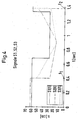
- the signals of the distance sensors S1, S2, S3 can be suitably evaluated will. 4 shows a possible time course of the signals of the distance sensors S1, S2, S3 when the material to be conveyed 2 runs at an angle.
- the material to be conveyed 2 enters the measuring range of the distance sensors S2 and S3.
- the distances to the front edge of the material to be conveyed 2 are measured.
- the measurement signals of the distance sensors S2 and S3 reach their respective minimum, ie at these times the edges pass the distance sensors S2 and S3.
- the signals from the distance sensors S2 and S3 then rise again until the material to be conveyed 2 leaves the measuring range of the distance sensors S2 and S3.
- the signals from the distance sensors S2 and S3 jump back to their starting position.
Landscapes
- Physics & Mathematics (AREA)
- General Physics & Mathematics (AREA)
- Length Measuring Devices By Optical Means (AREA)
- Length Measuring Devices With Unspecified Measuring Means (AREA)
Abstract
Description
Die Erfindung betrifft ein Verfahren und eine Einrichtung zum Messen des Volumens eines bewegten Fördergutes, insbesondere von Breite und Höhe eines Fördergutstückes, durch Abtasten mittels Strahlen in zumindest zwei Meßrichtungen, deren Meßergebnisse zur Berechnung der Volumengröße eingesetzt werden.The invention relates to a method and a device for measuring the volume of a moving material to be conveyed, in particular the width and height of a piece of material to be conveyed, by scanning in at least two measuring directions, the measurement results of which are used to calculate the volume size.
Bekannte und für die Fördertechnik anwendbare Verfahren zum Messen des Volumens eines bewegten Fördergutes bestehen zumeist aus einem Meßrahmen mit einem "Lichtschrankenmeßgitter". In diesem Lichtschrankenmeßgitter sind eine Vielzahl von Lichtschranken zum einen horizontal und senkrecht zur Förderrichtung und zum anderen vertikal ebenfalls senkrecht zur Förderrichtung angeordnet. Bedämpfte Lichtschranken horizontal, senkrecht zur Förderrichtung, ergeben die Höhe des Fördergutes, aus den vertikalen Lichtschranken wird die Breite des Fördergutes ermittelt. Die Länge des Fördergutes wird aus der Dauer der Lichtschrankendämpfung und der Fördergeschwindigkeit berechnet.Known and applicable methods for conveying technology for measuring the volume of a moving material usually consist of a measuring frame with a "light barrier measuring grid". In this light barrier measuring grid, a large number of light barriers are arranged, on the one hand, horizontally and perpendicular to the conveying direction and, on the other hand, also vertically likewise perpendicular to the conveying direction. Damped light barriers horizontally, perpendicular to the conveying direction, give the height of the material to be conveyed, and the width of the conveyed material is determined from the vertical light barriers. The length of the material to be conveyed is calculated from the duration of the light barrier damping and the conveying speed.
Für landwirtschaftliche Produkte ist bereits eine Sortiervorrichtung für Bohnen aufgrund eines optischen Sensors vorgeschlagen worden (DE 27 22 368.). Die Einrichtung umfaßt einen Durchgang, durch den die zu sortierenden Gegenstände hindurchgeführt werden unter Verwendung eines Beleuchtungssystems, das mit dem Durchgang verbunden ist, um eine kleine gleichmäßig geformte Lichtschicht zu erzeugen, die sich senkrecht zu dem Durchgang erstreckt und einen Lichtempfänger besitzt, der ebenfalls mit dem Durchgang verbunden ist, wodurch auf dem Licht beruhende Signale erzeugt werden, die von den Gegenständen reflektiert werden, die durch diese Lichtschicht laufen. Der Lichtempfänger empfängt ungerichtetes reflektiertes Licht und ist in der Lage, Licht von zwei unterschiedlichen Bandbreiten des Lichtspektrums zu messen. Beide Lichtbänder liegen innerhalb des sichtbaren oder infraroten Teils des Spektrums.A sorting device for beans based on an optical sensor has already been proposed for agricultural products (DE 27 22 368.). The device includes a passageway through which the items to be sorted are passed using an illumination system connected to the passageway to produce a small, uniformly shaped layer of light that extends perpendicular to the passageway and has a light receiver that is also included is connected to the passageway, thereby generating light-based signals that are reflected by the objects that pass through this light layer. The light receiver receives non-directional reflected light and is able to transmit light of two different bandwidths To measure light spectrum. Both light bands lie within the visible or infrared part of the spectrum.
Immer häufiger wird die Anforderung gestellt, das Volumen von Fördergut bei einer hohen Durchsatzrate, d.h. großer Fördergeschwindigkeit, zu messen. In vielen Anwendungsfällen ist für den Betreiber von Bedeutung, das Volumen zu messen, da die Anwender ihre Gebühren u.a. nach Frachtvolumen abrechnen müssen.There is an increasing demand for the volume of material to be conveyed at a high throughput rate, i.e. high conveyor speed to measure. In many applications, it is important for the operator to measure the volume, since the users charge their fees, among other things. have to bill for freight volume.
Der vorliegenden Erfindung liegt daher die Aufgabe zugrunde, ein Verfahren und eine Einrichtung zum Messen des Volumens eines bewegten Fördergutes vorzuschlagen, bei dem ein geringer verfahrenstechnischer bzw. einrichtungstechnischer Aufwand zu betreiben ist und dennoch eine ausreichend genaue Meßwertermittlung bzw. Berechnung des Volumens stattfinden können.The present invention is therefore based on the object of proposing a method and a device for measuring the volume of a conveyed material in which a low procedural and / or technical outlay is required and nevertheless a sufficiently precise measurement value determination or calculation of the volume can take place.
Die gestellte Aufgabe wird erfindungsgemäß dadurch gelöst, daß jeweils von einer Bezugsstelle aus der Abstand zum Fördergut in der Weise gemessen wird, daß zumindest mit einem ersten Abstandssensor parallel zur Förderebene und zumindest mit einem zweiten Abstandssensor vertikal zur Förderebene der Abstand zwischen der Bezugsstelle und der jeweiligen Fördergutoberfläche gemessen wird, wobei das Fördergut durch mechanische Maßnahmen auf einer vorherbestimmten Bewegungslinie gehalten wird oder durch Messungen eine Bewegungslinie ermittelt wird. Zunächst kommt dieses Verfahren mit zwei Meßwerten aus, wobei Meßprinzipien, wie optische, akustische, kapazitive, induktive Wegmessungen u.dgl. zum Einsatz kommen können.The object is achieved according to the invention in that the distance from the conveyed item is measured from a reference point in such a way that the distance between the reference point and the respective one is at least parallel to the conveying plane with at least one first distance sensor and perpendicular to the conveying plane with at least one second distance sensor Surface of the material being conveyed is measured, the material being conveyed being held on a predetermined movement line by mechanical measures or a movement line being determined by measurements. First of all, this method manages with two measured values, measuring principles such as optical, acoustic, capacitive, inductive displacement measurements and the like. can be used.
Nach weiteren Merkmalen ist vorgesehen, daß aus der zeitlichen Länge der Signale des ersten und/oder des zweiten Abstandssensors die zugehörige Länge des Fördergutes bestimmt wird.According to further features, it is provided that the associated length of the conveyed material is determined from the temporal length of the signals of the first and / or the second distance sensor.
Alternativ ist jedoch auch möglich, daß die Länge des Fördergutes durch ein das Fördergut an mehreren Seiten umgebendes Lichtschrankensystem und die damit verbundene Dämpfung der Meßstrahlen gemessen wird.Alternatively, however, it is also possible that the length of the material to be conveyed is measured by a light barrier system surrounding the material to be conveyed on several sides and the associated attenuation of the measuring beams.
Sofern das zu messende Fördergut nicht ausreichend genau auf der ermittelten Bewegungslinie gehalten werden kann, so daß ein Schrägliegen o.ä. stattfindet, wird vorgeschlagen, daß der Abstand parallel zur Fördermediumebene durch den zweiten Abstandssensor und einen dritten Abstandssensor gemessen wird, wobei der zweite und dritte Abstandssensor gegeneinander gerichtet arbeiten. In diesem Fall ist auch möglich, bei von einer gewollten Bezugslinie abweichenden Bewegung das Fördervolumen zu messen.If the material to be measured cannot be held with sufficient accuracy on the determined movement line, so that an incline or the like. takes place proposed that the distance parallel to the medium level is measured by the second distance sensor and a third distance sensor, the second and third distance sensors working in opposite directions. In this case it is also possible to measure the delivery volume if the movement deviates from a desired reference line.
Andererseits ist sehr vorteilhaft, wenn das Fördergut durch mechanische Maßnahmen plan an der einen Seite der Fördererbegrenzung während der Meßdauer gehalten wird. In diesem Fall bestehen keinerlei Probleme, die entsprechenden Messungen durchzuführen.On the other hand, it is very advantageous if the material to be conveyed is held flat by mechanical measures on one side of the conveyor limitation during the measuring period. In this case, there are no problems with taking the corresponding measurements.
In dieser Hinsicht ist außerdem vorteilhaft, daß bei schräg auf dem Fördermedium liegendem Fördergut durch eine kombinierte Auswertung von zumindest zwei antiparallel zur Fördererebene und einem vertikal auf das Fördergut bzw. die Fördermediumebene gerichteten Meßstrahl aus den drei Meßsignalen eine Volumenauswertung vorgenommen wird.In this regard, it is also advantageous that in the case of conveyed material lying obliquely on the conveying medium, a volume evaluation is carried out from the three measuring signals by a combined evaluation of at least two antiparallel to the conveying plane and a measuring beam directed vertically onto the conveying material or the conveying medium plane.
Eine Einrichtung zur Messung des Volumens eines bewegten Fördergutes, insbesondere von Breite und Höhe eines Fördergutstückes, durch Abtastung mittels Meßstrahlen in zumindest zwei Meßrichtungen, wobei die Meßergebnisse zur Berechnung der Volumengröße verwertbar sind, wird vorteilhafterweise dadurch geschaffen, daß außerhalb eines Fördermediums in einer Meßentfernung berührungslos arbeitende Abstandssensoren angeordnet sind, daß deren Meßstrahl quer zur Förderrichtung über der Fördermediumebene entsprechend dem niedrigsten Fördergut ausgerichtet ist und daß ein etwa vertikal verlaufender Meßstrahl entweder etwa mittig zum Förderer oder aber nahe zu einer Fördererbegrenzung verlaufend ausgerichtet ist. Die gesamte Meßeinrichtung kommt demzufolge mit zwei Abstandssensoren aus, wobei einer horizontal quer zur Förderrichtung, der andere vertikal arbeitet.A device for measuring the volume of a moving material to be conveyed, in particular the width and height of a piece of material to be conveyed, by scanning using measuring beams in at least two measuring directions, the measurement results being usable for calculating the volume size, is advantageously created by contactlessly outside of a conveying medium at a measuring distance Working distance sensors are arranged that their measuring beam is aligned transversely to the direction of conveyance above the level of the medium to be conveyed and that an approximately vertical measuring beam is either aligned approximately centrally to the conveyor or close to a conveyor limit. The entire measuring device therefore requires two distance sensors, one working horizontally across the conveying direction, the other vertically.
Nach weiteren Merkmalen der Erfindung ist vorgesehen, daß die Abstandssensoren aus optischen Sensoren oder aus Ultraschallsensoren gebildet sind.According to further features of the invention, it is provided that the distance sensors are formed from optical sensors or from ultrasonic sensors.
Weitere Vorteile ergeben sich dadurch, daß die optischen Abstandssensoren mit Schaltungen nach dem Prinzip der Triangulation, der Lichtstreuung, der Phasenverschiebung oder einem Laufzeitverfahren eingesetzt sind.
Für den Einsatz von Ultraschall-Sensoren ist vorgesehen, daß die Abstandssensoren mit Schaltungen nach dem Prinzip des Echolots oder des Sonars ausgeführt sind.Further advantages result from the fact that the optical distance sensors are used with circuits based on the principle of triangulation, light scattering, phase shift or a transit time method.
For the use of ultrasonic sensors it is provided that the distance sensors are designed with circuits based on the principle of the echo sounder or the sonar.
Ausführungsbeispiele der Erfindung sind in der Zeichnung dargestellt und werden im folgenden näher beschrieben. Es zeigen
- Fig. 1 A
- einen Querschnitt durch ein Fördermedium mit Abstandssensoren,
- Fig. 1 B
- die zu Fig. 1 A gehörende Draufsicht,
- Fig. 2 A
- einen Querschnitt durch das Fördermedium mit einer alternativen Meßlage des Fördergutes,
- Fig. 2 B
- die zu Fig. 2 A gehörende Draufsicht,
- Fig. 3 A
- denselben Querschnitt durch das Fördermedium für eine weitere alternative Meßmethode,
- Fig. 3 B
- die zu Fig. 3 A gehörende Draufsicht,
- Fig. 4
- ein Diagramm für den Zeitverlauf der Signale der Abstandssensoren S1, S2, S3 und
- Fig. 5
- ein Diagramm über die Geometrie des Fördergutes 2 und dessen Lage auf dem
Fördermedium 1.
- Fig. 1A
- a cross section through a medium with distance sensors,
- Fig. 1B
- 1 A is a top view,
- Fig. 2A
- a cross section through the medium with an alternative measuring position of the material to be conveyed,
- Fig. 2B
- the top view belonging to FIG. 2A,
- Fig. 3 A
- the same cross section through the pumped medium for another alternative measuring method,
- 3B
- the top view belonging to FIG. 3A,
- Fig. 4
- a diagram for the time course of the signals of the distance sensors S1, S2, S3 and
- Fig. 5
- a diagram of the geometry of the material to be conveyed 2 and its position on the conveying
medium 1.
Gemäß Fig. 1 besteht ein Fördermedium 1 aus einem Schrägrollenförderer 1a, an dessen Stelle auch ein Gurtförderer mit schrägem Lineal, ein Hochkantförderer oder eine andere mechanische Führung, ein Pusher o.dgl. treten kann. Das Fördergut 2 wird durch die gewollte Förderkraftkomponente stets gegen eine Förderer-Begrenzung 3 gedrückt, so daß seine Lage konstant ist in bezug auf eine Bezugsstelle 4. Von dieser Bezugsstelle 4 aus wird der Abstand zum Fördergut 2 in der Weise gemessen, daß zumindest mit einem ersten Abstandssensor S1 vertikal zur Fördermediumebene 5 und mit einem zweiten Abstandssensor S2 parallel zur Fördermediumebene 5 der Abstand zwischen der Bezugsstelle 4 und der jeweiligen Fördergutoberfläche 2a gemessen wird, wobei das Fördergut 2 durch mechanische Maßnahmen auf einer vorherbestimmten oder durch Messungen ermittelten Bewegungslinie 6 gehalten wird. Die Messungen können auf mehreren Sensoren beruhen.1, a conveying
Das Fördergut 2 tritt ab einer bestimmten Stelle in den Meßbereich der Abstandssensoren S1 und S2 ein. Der Abstandssensor S1 ermittelt durch Vergleich mit dem Meßsignal bei nicht vorhandenem Fördergut 2 (entspricht der Meßentfernung 9 zum Fördermedium 1) die Höhe des Fördergutes 2; dementsprechend ermittelt der Abstandssensor S2 die Breite des Fördergutes 2.The material to be conveyed 2 enters the measuring range of the distance sensors S1 and S2 from a certain point. The distance sensor S1 determines the height of the material to be conveyed 2 by comparison with the measurement signal when the material to be conveyed 2 is not present (corresponds to the
Aus der zeitlichen Länge der entstehenden Signale bei S1 oder S2 und der Fördergeschwindigkeit kann sodann die Länge des Fördergutes 2 ermittelt werden.The length of the material to be conveyed 2 can then be determined from the temporal length of the signals produced at S1 or S2 and the conveying speed.
Für den Ausnahmefall, daß die Abtastraten der Abstandssensoren S1 und S2 zu gering sind, kann die Aufgabe der Längenmessung auch einer herkömmlichen Lichtschranke übertragen werden, die zusätzlich parallel zum Abstandssensor S2 anzuordnen ist. Diese (nicht dargestellte) Lichtschranke wird kurz vor den Abstandssensoren S1 und S2 angebracht. Das Signal dieser Lichtschranke kann auch als Trigger für die Abstandssensoren S1 und S2 verwendet werden.In the exceptional case that the scanning rates of the distance sensors S1 and S2 are too low, the task of measuring the length can also be transferred to a conventional light barrier, which must also be arranged parallel to the distance sensor S2. This light barrier (not shown) is attached shortly in front of the distance sensors S1 and S2. The signal from this light barrier can also be used as a trigger for the distance sensors S1 and S2.
Die Länge des Fördergutes kann hingegen grundsätzlich auch durch ein das Fördergut 2 an mehreren Seiten umgebendes Lichtschrankensystem und die damit verbundene Dämpfung der Meßstrahlen gemessen werden, wobei auch von der Unterseite her gearbeitet bzw. gemessen werden kann.In contrast, the length of the material to be conveyed can in principle also be measured by a light barrier system surrounding the material to be conveyed 2 on several sides and the associated attenuation of the measuring beams, it also being possible to work or measure from the underside.
Für die Anordnung des Abstandssensors S1 ist wichtig, daß dieser so weit wie möglich an die Begrenzung 3 (in den Fig. 1 A und 1 B nach links) montiert wird, wodurch auch die Höhe sehr schmalen Fördergutes 2 gemessen werden kann.For the arrangement of the distance sensor S1, it is important that it is mounted as far as possible on the limit 3 (to the left in FIGS. 1A and 1B), as a result of which the height of very narrow conveyed
Auf die Funktion der Seitenbegrenzung 3 und eines Schrägrollenförderers 1a kann verzichtet werden, wenn der Abstand parallel zur Fördermediumebene 5 durch den zweiten Abstandssensor S2 und einen dritten Abstandssensor S3 gemessen wird, wobei der zweite Abstandssensor S2 und der dritte Abstandssensor S3 gegeneinander gerichtet arbeiten (Fig. 2 A und 2 B).The function of the
Der Schrägrollenförderer 1a stellt sicher, daß durch mechanische Maßnahmen das Fördergut 2 plan an der einen Seite der Förderer-Begrenzung 3 während seiner Bewegung gehalten wird.The
Aus den Signalen der Abstandssensoren S2 und S3 und der bekannten geometrischen Anordnung der Abstandssensoren S2 und S3 berechnet sich ebenfalls die Breite des Fördergutes 2. Für die Berechnung des Fördergut-Volumens ist es bei der Anordnung gemäß den Fig. 2 A und 2 B nicht mehr notwendig, daß das Fördergut 2 bündig zu der Förderer-Begrenzung 3 transportiert wird, wohl aber muß das Fördergut 2 parallel zur Förderrichtung 7 ausgerichtet sein.The width of the material to be conveyed 2 is also calculated from the signals from the distance sensors S2 and S3 and the known geometric arrangement of the distance sensors S2 and S3. The arrangement according to FIGS. 2A and 2B is no longer used to calculate the volume of the material to be conveyed necessary that the conveyed
Bei schräg auf dem Fördermedium 1 liegendem Fördergut 2 (Fig. 3 A und 3 B) wird durch eine kombinierte Auswertung von zumindest zwei parallel zur Fördermediumebene 5 und einem vertikal auf das Fördergut 2 bzw. die Fördermediumebene gerichteten Meßstrahl 8 aus den drei Meßsignalen der Abstandssensoren S1, S2, S3 eine Volumenauswertung vorgenommen.In the case of conveyed
Die Abstandssensoren S1, S2 (S3) sind jeweil in einer Meßentfernung 9 berührungslos arbeitend angeordnet. Der Meßstrahl 8 ist jeweils quer zur Förderrichtung 7 über der Fördermediumebene 5 entsprechend dem niedrigsten Fördergut 2 ausgerichtet und ein etwa vertikal verlaufender Meßstrahl 8 ist entweder etwa mittig zum Fördermedium 1 oder aber nahe zu einer Fördererbegrenzung 3 verlaufend ausgerichtet.The distance sensors S1, S2 (S3) are each arranged to work in a contact distance at a
Die Abstandssensoren S1, S2, S3 sind aus optischen Sensoren oder aus UltraschallSensoren gebildet. Die optischen Abstandssensoren S1, S2, S3 sind dabei mit Schaltungen nach dem Prinzip der Triangulation, der Lichtstreuung, der Phasenverschiebung oder einem Laufzeitverfahren einsetzbar. Die Abstandssensoren S1, S2, S3 können auch mit Schaltungen nach dem Prinzip des Echolots oder des Sonars ausgeführt sein.The distance sensors S1, S2, S3 are formed from optical sensors or from ultrasonic sensors. The optical distance sensors S1, S2, S3 can be used with circuits based on the principle of triangulation, light scattering, phase shift or a runtime method. The distance sensors S1, S2, S3 can also be designed with circuits based on the principle of the echo sounder or sonar.
Bei schrägliegendem Fördergut 2 (entsprechend den Fig. 3 A und 3 B) kann eine geeignete Auswertung der Signale der Abstandssensoren S1, S2, S3 vorgenommen werden. Gemäß Fig. 4 ist ein möglicher Zeitverlauf der Signale der Abstandssensoren S1, S2, S3 bei schräg durchlaufendem Fördergut 2 dargestellt. Zum Zeitpunkt t1 = 0,4 tritt das Fördergut 2 in den Meßbereich der Abstandssensoren S2 und S3. Zu diesem Zeitpunkt werden die Abstände zur vorderen Kante des Fördergutes 2 gemessen. Zu prinzipiell unterschiedlichen Zeitpunkten erreichen die Meßsignale der Abstandssensoren S2 und S3 ihr jeweiliges Minimum, d.h. zu diesen Zeitpunkten passieren die Kanten die Abstandssensoren S2 und S3. Die Signale der Abstandssensoren S2 und S3 steigen anschließend wieder an, bis das Fördergut 2 den Meßbereich der Abstandssensoren S2 und S3 verläßt. In diesem Moment t2 springen die Signale der Abstandssensoren S2 und S3 sprungartig in ihre Ausgangsposition zurück.In the case of inclined conveyed goods 2 (corresponding to FIGS. 3A and 3B), the signals of the distance sensors S1, S2, S3 can be suitably evaluated will. 4 shows a possible time course of the signals of the distance sensors S1, S2, S3 when the material to be conveyed 2 runs at an angle. At the time t 1 = 0.4, the material to be conveyed 2 enters the measuring range of the distance sensors S2 and S3. At this time, the distances to the front edge of the material to be conveyed 2 are measured. At fundamentally different times, the measurement signals of the distance sensors S2 and S3 reach their respective minimum, ie at these times the edges pass the distance sensors S2 and S3. The signals from the distance sensors S2 and S3 then rise again until the material to be conveyed 2 leaves the measuring range of the distance sensors S2 and S3. At this moment t 2, the signals from the distance sensors S2 and S3 jump back to their starting position.
Aus dem Verlauf der Signale der Abstandssensoren S1, S2 und S3 kann auf die Geometrie des Fördergutes 2 zurückgeschlossen werden. Bei bekannter Fördergeschwindigkeit v ergibt sich der zurückgelegte Weg![]()

![]()
Über die Breite b des Fördermediums 1 - sie entspricht prinzipiell jeweils dem Leersignal S2 bzw. S3 wenn kein Fördergut 2 sich im Meßbereich befindet - und den beiden Integrationsgrenzen s1 und s2 kann die Grundfläche A des Fördergutes 2 berechnet werden:![]()
- b
- = Breite des
Fördermediums 1 - A
- = Grundfläche des Fördergutes 2
- s1
- = Integrationsgrenze
- s2
- = Integrationsgrenze
- b
- = Width of the pumped
medium 1 - A
- = Base area of the conveyed
goods 2 - s 1
- = Integration limit
- s 2
- = Integration limit
- 11
- FördermediumPumped medium
- 1a1a
- SchrägrollenfördererInclined roller conveyor
- 22nd
- FördergutMaterial to be conveyed
- 2a2a
- FördergutoberflächeConveyed goods surface
- 33rd
- Förderer-BegrenzungConveyor limit
- 44th
- BezugsstelleReference point
- 55
- FördermediumebeneMedium level
- 66
- BewegungslinieLine of motion
- S1S1
- AbstandssensorDistance sensor
- S2S2
- AbstandssensorDistance sensor
- S3S3
- AbstandssensorDistance sensor
- 77
- FörderrichtungDirection of conveyance
- 88th
- MeßstrahlenMeasuring beams
- 99
- MeßentfernungMeasuring distance
Claims (10)
dadurch gekennzeichnet,
daß jeweils von einer Bezugsstelle aus der Abstand zum Fördergut in der Weise gemessen wird, daß zumindest mit einem ersten Abstandssensor parallel zur Fördermediumebene und zumindest mit einem zweiten Abstandssensor vertikal zur Fördermediumebene der Abstand zwischen der Bezugsstelle und der jeweiligen Fördergutoberfläche gemessen wird, wobei das Fördergut durch mechanische Maßnahmen auf einer vorherbestimmten Bewegungslinie gehalten wird oder durch Messungen eine Bewegungslinie ermittelt wird.Method for measuring the volume of a moving material to be conveyed, in particular the width and height of a piece of material to be conveyed, by scanning with measuring beams in at least two measuring directions, the results of which are used to calculate the volume size,
characterized,
that in each case the distance to the conveyed item is measured from a reference point in such a way that the distance between the reference point and the respective conveyed item surface is measured at least with a first distance sensor parallel to the conveying medium level and at least with a second distance sensor, the conveyed item being measured by mechanical measures are kept on a predetermined movement line or a movement line is determined by measurements.
dadurch gekennzeichnet,
daß aus der zeitlichen Länge der Signale des ersten und/oder des zweiten Abstandssensors die zugehörige Länge des Fördergutes bestimmt wird.Method according to claim 1,
characterized,
that the associated length of the conveyed material is determined from the temporal length of the signals of the first and / or the second distance sensor.
dadurch gekennzeichnet,
daß die Länge des Fördergutes durch ein das Fördergut an mehreren Seiten umgebendes Lichtschrankensystem und die damit verbundene Dämpfung der Meßstrahlen gemessen wird.Method according to claim 1,
characterized,
that the length of the material to be conveyed is measured by a light barrier system surrounding the material to be conveyed on several sides and the associated attenuation of the measuring beams.
dadurch gekennzeichnet,
daß der Abstand parallel zur Fördermediumebene durch den zweiten Abstandssensor und einen dritten Abstandssensor gemessen wird, wobei der zweite und dritte Abstandssensor gegeneinandergerichtet arbeiten.Method according to one of claims 1 to 3,
characterized,
that the distance parallel to the medium level is measured by the second distance sensor and a third distance sensor, the second and third distance sensors working in opposite directions.
dadurch gekennzeichnet,
daß das Fördergut durch mechanische Maßnahmen plan an der einen Seite der Fördererbegrenzung während der Meßdauer gehalten wird.Method according to one of claims 1 to 3,
characterized,
that the conveyed material is held flat by mechanical measures on one side of the conveyor limitation during the measurement period.
dadurch gekennzeichnet,
daß bei schräg auf dem Fördermedium liegendem Fördergut durch eine kombinierte Auswertung von zumindest zwei antiparallel zur Fördermediumebene und einem vertikal auf das Fördergut bzw. die Fördermediumebene gerichteten Meßstrahl aus den drei Meßsignalen eine Volumenauswertung vorgenommen wird.Method according to one of claims 1 to 5,
characterized,
that with conveyed material lying at an angle on the conveyed medium, a volume evaluation is carried out from the three measurement signals by a combined evaluation of at least two antiparallel to the conveyed medium level and a measuring beam directed vertically onto the conveyed medium or the conveyed medium level.
dadurch gekennzeichnet,
daß außerhalb eines Fördermediums (1) in einer Meßentfernung (9) berührungslos arbeitende Abstandssensoren (S1,S2; S3) angeordnet sind, daß deren Meßstrahl (8) quer zur Förderrichtung (7) über der Fördermediumebene (5) entsprechend dem niedrigsten Fördergut (2) ausgerichtet ist und daß ein etwa vertikal verlaufender Meßstrahl (8) entweder etwa mittig zum Fördermedium (1) oder aber nahe zu einer Fördererbegrenzung (3) verlaufend ausgerichtet ist.Device for measuring the volume of a moving material to be conveyed, in particular the width and height of a piece of material to be conveyed, by scanning using measuring beams in at least two measuring directions, the measuring results being usable for calculating the volume size,
characterized,
that non-contact distance sensors (S1, S2; S3) are arranged outside a conveying medium (1) at a measuring distance (9), that their measuring beam (8) transversely to the conveying direction (7) above the conveying medium level (5) corresponding to the lowest conveyed material (2 ) is aligned and that an approximately vertical measuring beam (8) is either aligned approximately centrally to the medium (1) or close to a conveyor limit (3).
dadurch gekennzeichnet,
daß die Abstandssensoren (S1, S2, S3) aus optischen Sensoren oder aus Ultraschallsensoren gebildet sind.Device according to claim 7,
characterized,
that the distance sensors (S1, S2, S3) are formed from optical sensors or from ultrasonic sensors.
dadurch gekennzeichnet,
daß die optischen Abstandssensoren (S1,S2,S3) mit Schaltungen nach dem Prinzip der Triangulation, der Lichtstreuung, der Phasenverschiebung oder einem Laufzeitverfahren eingesetzt sind.Device according to one of claims 7 or 8,
characterized,
that the optical distance sensors (S1, S2, S3) are used with circuits based on the principle of triangulation, light scattering, phase shift or a transit time method.
dadurch gekennzeichnet,
daß die Abstandssensoren (S1, S2, S3) mit Schaltungen nach dem Prinzip des Echolots oder des Sonars ausgeführt sind.Device according to one of claims 7 to 9,
characterized,
that the distance sensors (S1, S2, S3) are designed with circuits based on the principle of the sonar or sonar.
Applications Claiming Priority (2)
| Application Number | Priority Date | Filing Date | Title |
|---|---|---|---|
| DE19505509 | 1995-02-10 | ||
| DE1995105509 DE19505509C2 (en) | 1995-02-10 | 1995-02-10 | Method and device for measuring the volume of a moving material |
Publications (2)
| Publication Number | Publication Date |
|---|---|
| EP0726445A2 true EP0726445A2 (en) | 1996-08-14 |
| EP0726445A3 EP0726445A3 (en) | 1997-11-12 |
Family
ID=7754322
Family Applications (1)
| Application Number | Title | Priority Date | Filing Date |
|---|---|---|---|
| EP96250013A Withdrawn EP0726445A3 (en) | 1995-02-10 | 1996-01-19 | Procedure and device to measure the volume of a moving object |
Country Status (2)
| Country | Link |
|---|---|
| EP (1) | EP0726445A3 (en) |
| DE (1) | DE19505509C2 (en) |
Cited By (5)
| Publication number | Priority date | Publication date | Assignee | Title |
|---|---|---|---|---|
| EP0837300A2 (en) * | 1996-10-21 | 1998-04-22 | Carl Zeiss | Procedure to measure the contours of objects |
| EP1070935A3 (en) * | 1999-07-08 | 2002-04-10 | Bayer Bitterfeld GmbH | Device to control the width of sealing joints |
| EP1621849A1 (en) * | 2002-12-20 | 2006-02-01 | Sick Ag | Method and apparatus for detecting objects moved on a conveyor by means of an optoelectronic sensor |
| CN109422092A (en) * | 2017-08-23 | 2019-03-05 | 中国南玻集团股份有限公司 | Multi-functional transmission platform and board dimension measuring system and method |
| CN114777702A (en) * | 2022-04-22 | 2022-07-22 | 成都市绿色快线环保科技有限公司 | Stacked plate volume identification method, device and system |
Families Citing this family (5)
| Publication number | Priority date | Publication date | Assignee | Title |
|---|---|---|---|---|
| DE19721711C2 (en) * | 1997-05-23 | 2002-10-10 | Wipotec Wiege & Positioniersys | Device for determining the format of general cargo, in particular mail items |
| DE19722066A1 (en) * | 1997-05-27 | 1998-12-03 | Smb Schwede Maschinenbau Gmbh | Strapping machine for strapping objects with an object height-dependent tensioning device |
| DE19724156C2 (en) * | 1997-06-07 | 2001-12-13 | Fette Wilhelm Gmbh | Method and device for measuring the functional length of press rams |
| DE10315902A1 (en) * | 2003-04-08 | 2004-11-04 | Anatec Gmbh | Volume flow measurement method for bulk loose material, e.g. for use in materials handling stations, employs two or more contactless measurement methods in order to determine an optimum reference measurement values |
| CH715506A1 (en) * | 2018-10-31 | 2020-05-15 | Ferag Ag | Storage device for storing transport units. |
Citations (1)
| Publication number | Priority date | Publication date | Assignee | Title |
|---|---|---|---|---|
| DE2722368A1 (en) | 1976-05-19 | 1977-12-01 | Ultra Sort Corp | SORTING DEVICE WITH OPTICAL SCANNER |
Family Cites Families (5)
| Publication number | Priority date | Publication date | Assignee | Title |
|---|---|---|---|---|
| US3588480A (en) * | 1968-12-06 | 1971-06-28 | Fairbanks Morse Inc | Processing control system |
| US4417817A (en) * | 1980-06-19 | 1983-11-29 | General Mining Union Corporation, Limited | Volumetric measurement of particles |
| US5220536A (en) * | 1989-09-01 | 1993-06-15 | Quantronix, Inc. | Measuring method and apparatus |
| DE4318341B4 (en) * | 1993-04-10 | 2009-02-19 | Christoph Schausten | Method for storing pharmacy articles and device for carrying out such a method |
| ES2104219T5 (en) * | 1993-04-10 | 2002-04-01 | Christoph Schausten | PROCEDURE FOR STORAGE OF PACKED MATERIAL AND DEVICE FOR THE PERFORMANCE OF THE PROCEDURE. |
-
1995
- 1995-02-10 DE DE1995105509 patent/DE19505509C2/en not_active Expired - Fee Related
-
1996
- 1996-01-19 EP EP96250013A patent/EP0726445A3/en not_active Withdrawn
Patent Citations (1)
| Publication number | Priority date | Publication date | Assignee | Title |
|---|---|---|---|---|
| DE2722368A1 (en) | 1976-05-19 | 1977-12-01 | Ultra Sort Corp | SORTING DEVICE WITH OPTICAL SCANNER |
Cited By (10)
| Publication number | Priority date | Publication date | Assignee | Title |
|---|---|---|---|---|
| EP0837300A2 (en) * | 1996-10-21 | 1998-04-22 | Carl Zeiss | Procedure to measure the contours of objects |
| EP0837300A3 (en) * | 1996-10-21 | 2001-03-21 | Carl Zeiss | Procedure to measure the contours of objects |
| EP1070935A3 (en) * | 1999-07-08 | 2002-04-10 | Bayer Bitterfeld GmbH | Device to control the width of sealing joints |
| US6717087B1 (en) * | 1999-07-08 | 2004-04-06 | Bayer Bitterfeld Gmbh | Monitoring device for the sealing web width |
| EP1621849A1 (en) * | 2002-12-20 | 2006-02-01 | Sick Ag | Method and apparatus for detecting objects moved on a conveyor by means of an optoelectronic sensor |
| EP1431707B1 (en) * | 2002-12-20 | 2006-08-02 | Sick AG | Method and device for the acquisition of objects on a conveyor by optoelectronic means |
| US7199385B2 (en) | 2002-12-20 | 2007-04-03 | Sick Ag | Method and an apparatus for the detection of objects moved on a conveyor means by means of an optoelectronic sensor |
| CN109422092A (en) * | 2017-08-23 | 2019-03-05 | 中国南玻集团股份有限公司 | Multi-functional transmission platform and board dimension measuring system and method |
| CN114777702A (en) * | 2022-04-22 | 2022-07-22 | 成都市绿色快线环保科技有限公司 | Stacked plate volume identification method, device and system |
| CN114777702B (en) * | 2022-04-22 | 2024-03-12 | 成都市绿色快线环保科技有限公司 | Stacked plate volume identification method, device and system thereof |
Also Published As
| Publication number | Publication date |
|---|---|
| DE19505509C2 (en) | 2003-01-30 |
| DE19505509A1 (en) | 1996-08-14 |
| EP0726445A3 (en) | 1997-11-12 |
Similar Documents
| Publication | Publication Date | Title |
|---|---|---|
| DE3411540C2 (en) | ||
| DE3642377A1 (en) | METHOD AND DEVICE FOR MEASURING THE THICKNESS OF A FILM OR LEAF-LIKE MATERIAL | |
| EP2246673A1 (en) | Method for determining the volume of loads and device | |
| DE2546714C2 (en) | ||
| DE3735905A1 (en) | Method and device for volume flow measurement on conveyor belts by means of a laser distance profile scanner | |
| EP0086803A1 (en) | Method and device for estimating the shots on a target. | |
| DE2713844C3 (en) | Device for recognizing the value of coins or the like. Objects | |
| EP0726445A2 (en) | Procedure and device to measure the volume of a moving object | |
| DE2555975A1 (en) | Optoelectrical dimension measurement of moving objects - uses silhouette sensing technique for objects on conveyor such as dia. of wooden logs | |
| EP1024372A1 (en) | Device for position detection | |
| EP1653202A1 (en) | Method and device for measurement of a volume flow of a belt conveyor | |
| EP0361071B1 (en) | Method and device for counting flat objects arriving in overlapping fashion, such as sheets, periodicals and the like | |
| DE1804600A1 (en) | Device for thickness measurement with ultrasound | |
| DE3913159A1 (en) | Measuring wave-shaped rail deformation - using vehicle with two sensors measuring height difference of two rail top points | |
| DE69629482T2 (en) | Method and apparatus for measuring the volume of an object by means of a laser scanner | |
| DE10060144A1 (en) | Thickness measuring device for sheet or web material uses optical distance measuring devices on opposite sides of sheet or web | |
| DE2124444A1 (en) | Method for determining the thickness or width of workpieces | |
| DE2436510A1 (en) | DEVICE FOR DETERMINING THE POSITION OF A PIECE | |
| DE19625055B4 (en) | Device and method for measuring the diameter of objects | |
| DE3522809C2 (en) | ||
| WO2005022079A1 (en) | Device for determining the volume of transported material | |
| AT509885B1 (en) | APPARATUS AND METHOD FOR COIN DETECTION | |
| EP4040188B1 (en) | Device and method for measuring an object | |
| DE102004021447A1 (en) | Adhesive application inspection unit moves along fillet and triangulates distance using modulated laser light | |
| DE19913928B4 (en) | Device for determining properties of a moving material web |
Legal Events
| Date | Code | Title | Description |
|---|---|---|---|
| PUAI | Public reference made under article 153(3) epc to a published international application that has entered the european phase |
Free format text: ORIGINAL CODE: 0009012 |
|
| AK | Designated contracting states |
Kind code of ref document: A2 Designated state(s): AT DE DK FR GB IT NL |
|
| PUAL | Search report despatched |
Free format text: ORIGINAL CODE: 0009013 |
|
| AK | Designated contracting states |
Kind code of ref document: A3 Designated state(s): AT DE DK FR GB IT NL |
|
| 17P | Request for examination filed |
Effective date: 19980512 |
|
| 17Q | First examination report despatched |
Effective date: 20010424 |
|
| STAA | Information on the status of an ep patent application or granted ep patent |
Free format text: STATUS: THE APPLICATION HAS BEEN WITHDRAWN |
|
| 18W | Application withdrawn |
Withdrawal date: 20010830 |