EP0725040A1 - Coalescence separator - Google Patents
Coalescence separator Download PDFInfo
- Publication number
- EP0725040A1 EP0725040A1 EP94119576A EP94119576A EP0725040A1 EP 0725040 A1 EP0725040 A1 EP 0725040A1 EP 94119576 A EP94119576 A EP 94119576A EP 94119576 A EP94119576 A EP 94119576A EP 0725040 A1 EP0725040 A1 EP 0725040A1
- Authority
- EP
- European Patent Office
- Prior art keywords
- coalescence
- insert
- separator according
- backwashing
- coalescence separator
- Prior art date
- Legal status (The legal status is an assumption and is not a legal conclusion. Google has not performed a legal analysis and makes no representation as to the accuracy of the status listed.)
- Withdrawn
Links
Images


Classifications
-
- E—FIXED CONSTRUCTIONS
- E03—WATER SUPPLY; SEWERAGE
- E03F—SEWERS; CESSPOOLS
- E03F5/00—Sewerage structures
- E03F5/14—Devices for separating liquid or solid substances from sewage, e.g. sand or sludge traps, rakes or grates
- E03F5/16—Devices for separating oil, water or grease from sewage in drains leading to the main sewer
-
- B—PERFORMING OPERATIONS; TRANSPORTING
- B01—PHYSICAL OR CHEMICAL PROCESSES OR APPARATUS IN GENERAL
- B01D—SEPARATION
- B01D17/00—Separation of liquids, not provided for elsewhere, e.g. by thermal diffusion
- B01D17/02—Separation of non-miscible liquids
- B01D17/0208—Separation of non-miscible liquids by sedimentation
- B01D17/0214—Separation of non-miscible liquids by sedimentation with removal of one of the phases
-
- B—PERFORMING OPERATIONS; TRANSPORTING
- B01—PHYSICAL OR CHEMICAL PROCESSES OR APPARATUS IN GENERAL
- B01D—SEPARATION
- B01D17/00—Separation of liquids, not provided for elsewhere, e.g. by thermal diffusion
- B01D17/02—Separation of non-miscible liquids
- B01D17/04—Breaking emulsions
- B01D17/045—Breaking emulsions with coalescers
Definitions
- Coalescence separators which are separators that work on the calming principle with a flow-through coalescence insert that is structured in such a way that the finely dispersed light liquids present in the waste water coalesce.
- the coalesced light liquids rise to the surface of the separator contents and can be removed from there.
- the coalescence inserts have to be cleaned from time to time.
- the inserts are removed and cleaned in a suitable station with sharp rinsing jets.
- the rinsing sludge must be collected and then disposed of.
- This type of cleaning of the coalescence inserts requires a lot of time and resources and is also dependent on the reliability of the staff. It may happen that the cleaning is made volatile and incomplete. There is also an increasing desire to clean the coalescence inserts at certain shorter intervals without removal.
- a very effective design of a coalescence separator is one in which the coalescence insert has the shape of a hollow cylinder and is placed vertically axis over the lower clear water outlet. This coalescence insert is flowed through from outside to inside (DE-A 37 04 911). The Coalescence inserts are pulled out for cleaning and, for example, driven to the cleaning station in a specially designed vehicle (DE-U-89 04 912). There are also cleaning devices in the form of permanently installed rinsing nozzle tubes (DE-A 33 29 869) for coalescence inserts which run horizontally and flow from top to bottom.
- a backwashing device with outwardly directed nozzles or the like is provided inside the coalescence insert which essentially sweeps the entire inner surface .
- this device is fed backwashing liquid under pressure.
- the flushing sludge from outside is disposed of.
- a bell housing provided with a suction connection, which has a hollow cylindrical shape spanning the coalescence insert and is slipped over the insert during backwashing. The rinsing sludge is then suctioned off immediately after it leaves the insert.
- the hollow cylindrical coalescence insert has an inner cage consisting of a plurality of vertically running rods, then it is advantageous to form at least one of the rods in a tubular shape and to provide rows of outwardly directed nozzle holes or slots distributed over its length.
- the nozzle pipes are connected to a distributor ring pipe.
- coalescence insert is equipped with a lifting and subsequent rotating device.
- a removable backwashing device comes into question, which in particular can again consist of a series of vertical nozzle pipes or several horizontal ring pipes or a nozzle disk. Devices that only have an annular tube or a nozzle disk are moved up and down during backwashing and, if necessary, rotated in the process. A combination of vertical nozzle tubes and ring tubes is also conceivable. Finally, it is also possible to use a hose provided with a detergent connection, which has sleeves or the like at intervals with nozzles. This tubular backwashing device can e.g. spirally wrapped around the cage. Several short hose sections can be attached to the bars of the cage and connected at the top by an annular tube.
- a final embodiment of the invention consists of two concentrically and coaxially arranged tubes, which are tightly connected and equipped with a detergent connection to the cavity.
- the flushing nozzles or slots are in the outer tube. This backwashing device is only suitable for temporary insertion in the coalescence insert.
- the separator is a monolithic, ie in one piece made of reinforced concrete basin 1, which is covered at the top by a ceiling 2, which in turn has a maintenance opening 3 and has a manhole cover 4.
- Inlet and outlet connections 5, 6 are guided flexibly through wall flanges 7.
- the clear water outlet fitting 8 contains at the inlet opening a valve seat 9 for the float closure 10 prescribed in accordance with DIN 1999, which is tared to the density difference between water and light liquid.
- the valve seat 9 is preceded by the hollow cylindrical coalescence insert 11, which is attached to the cage 12 which guides the float 10.
- the cage 12 contains tubes 13 instead of the vertical rods, which are equipped with radially outwardly directed nozzles 14 along their length.
- the tubes 13 are connected to a distributor ring tube 15, which contains a connecting piece 16 for the detergent hose 17.
- the detergent hose is installed on the wall of the separator basin.
- the hose coupling 18 is easily accessible in the maintenance shaft.
- Fig. 3 shows the backwashing process by arrows 19.
- detergent - drinking water process water or air - is supplied under pressure.
- the rinsing jets loosen the deposits in the coalescence insert and wash them outwards.
- the mud should be given the opportunity to separate light and heavy materials. If the backwashing process was carried out with the separator emptied, the flushing sludge can then also be suctioned off and disposed of in accordance with regulations.
- the backwash insert 12 can also be removed for maintenance and repair purposes after the coalescence insert has been removed.
- the two components can even be connected to one another and then removed together.
- the coalescence separator according to FIG. 4 is identical to that according to FIG. 1, which is why its details are no longer discussed here.
- the cage 12 ' which serves the float closure 10 as a guide and the coalescing insert 11 as a holder, however, consists in a conventional manner of solid round rods 13', which are held together by a ring 20 and below by the valve seat ring 9.
- a hose 21 is spirally wound onto the cage 12 'in the space between the somewhat larger coalescence insert 11. 6, the hose has a plurality of sleeves 22 which contain the flushing nozzles 23.
- Each sleeve preferably has three nozzles which spread the backwashing agent in a fan shape and thus cover a larger area section.
- the cage, hose and coalescence insert are advantageously mounted outside the separator and then installed as a unit. However, for intensive cleaning outside the separator, it only makes sense to be able to remove only the coalescence insert.
- FIGS. 7 to 9 show backwashing devices which are only introduced into the coalescing insert for backwashing.
- This technique has the advantage that several coalescence separators can be operated with such a device.
- the backwash effect depends on how thoroughly the operator moves the backwashing device over the inner surface of the coalescence insert.
- the backwashing device according to FIG. 7 consists of four vertical wash pipes 13 ′′, which are connected at the top by a distributor cross 25. In the middle of the distributor cross 25, the detergent nozzle 26 is connected. This nozzle also serves as a handle.
- a dome 28 hangs on a chain 27 and closes the clear water outlet during backwashing, so that no washing sludge gets into the outlet line.
- the flushing device according to FIG. 8 contains a single ring tube 33 and according to FIG. 9 a hollow disc 43 with a ring of flushing nozzles 34 (here in particular in the form of a slot).
- the backwashing device according to FIG. 10 can be of a permanently installed type or only introduced for backwashing.
- this flushing device has a plurality of half-ring tubes 45 which lie opposite one another. They can also be offset from one another in height, so that when the backwashing device is rotated, a larger area of the coalescence insert is covered.
- the nozzle tubes can also be designed as closed rings 44 and then arranged obliquely.
- a hollow cylindrical bell 30 is placed over the coalescence insert 11 during backwashing.
- the bell contains a suction connection 31, to which a suction pump is connected during backwashing. This can be the pump of the Be disposal vehicle, which then immediately removes the mud.
- the backwashing process is actively supported by suction.
- the embodiment of the invention according to FIG. 12 contains a double pipe 35, 36 as backwashing device, the cavity of which is supplied with detergent via a distribution pipe 37.
- the outer tube 35 contains a plurality of nozzle holes or slots distributed along the length and circumference. This flushing device cannot remain in the separator during the separator operation, because it would make the flow of the waste water through the coalescence insert impossible.
- the exemplary embodiment according to FIGS. 13 and 14 differs from the ones described above in that only one fixed row of nozzles 53 is provided, which is part of the inner cage 12 and contains a hose connection 17.
- the spindle 29 mounted on a crossbar 38 is actuated, which first lifts the coalescence insert 11 and then rotates it. After backwashing, the coalescence insert is lowered back into its seat.
Landscapes
- Physics & Mathematics (AREA)
- Thermal Sciences (AREA)
- Chemical & Material Sciences (AREA)
- Chemical Kinetics & Catalysis (AREA)
- Health & Medical Sciences (AREA)
- Life Sciences & Earth Sciences (AREA)
- Engineering & Computer Science (AREA)
- Hydrology & Water Resources (AREA)
- Public Health (AREA)
- Water Supply & Treatment (AREA)
- Cleaning In General (AREA)
Abstract
Description
Die Erfindung bezieht sich auf sog. Koaleszenzabscheider, das sind nach dem Beruhigungsprinzip arbeitende Abscheider mit einem durchströmten Koaleszenzeinsatz, der so strukturiert ist, daß es zu einer Koaleszenz der im Abwasser vorhandenen feinst dispergierten Leichtflüssigkeiten kommt. Die koaleszierten Leichtflüssigkeiten steigen zur Oberfläche des Abscheiderinhalts und können von dort abgezogen werden.The invention relates to so-called. Coalescence separators, which are separators that work on the calming principle with a flow-through coalescence insert that is structured in such a way that the finely dispersed light liquids present in the waste water coalesce. The coalesced light liquids rise to the surface of the separator contents and can be removed from there.
Da mit dem Abwasser neben den Leichtflüssigkeiten auch Schwerstoffe herangeführt werden, die überwiegend an die Leichtflüssigkeitströpfchen angelagert sind, können diese Aggregate wegen der nahe bei 1 liegenden spezifischen Dichte nicht abgeschieden werden, sie lagern sich in den Poren des Koaleszenzeinsatzes ab. Um einen Stau auf der Zulaufseite zu vermeiden, müssen die Koaleszenzeinsätze daher von Zeit zu Zeit gesäubert werden. Hierfür werden die Einsätze herausgenommen und in einer dafür geeigneten Station mit scharfen Spülstrahlen gereinigt. Der Spülschlamm muß aufgefangen und anschließend entsorgt werden. Diese Art der Reinigung der Koaleszenzeinsätze ist mit einem hohen Zeit- und Arbeitsmittelaufwand verbunden und darüber hinaus von der Zuverlässigkeit des Personals abhängig. Es dürfte vorkommen, daß die Reinigung flüchtig und unvollständig gemacht wird. Auch wird zunehmend der Wunsch geäußert, die Koaleszenzeinsätze in bestimmten kürzeren Zeitabständen ohne Ausbau zwischenzureinigen.Since the wastewater in addition to the light liquids also brings heavy substances that are predominantly attached to the light liquid droplets, these aggregates cannot be separated due to the specific density close to 1, they accumulate in the pores of the Coalescence insert. In order to avoid a jam on the inlet side, the coalescence inserts have to be cleaned from time to time. For this purpose, the inserts are removed and cleaned in a suitable station with sharp rinsing jets. The rinsing sludge must be collected and then disposed of. This type of cleaning of the coalescence inserts requires a lot of time and resources and is also dependent on the reliability of the staff. It may happen that the cleaning is made volatile and incomplete. There is also an increasing desire to clean the coalescence inserts at certain shorter intervals without removal.
Bei Koaleszenzabscheidern, die mit einem quer in den Abscheidequerschnitt eingesetzten flächigen Einsatz ausgestattet sind, ist bereits vorgeschlagen worden, diese Zwischenreinigung durch ein Düsenrohr durchzuführen, das auf der Abströmseite des Einsatzes liegt und in Vertikalführungen auf- und abbewegt werden kann (DE-C- 34 03 718). Es ist bekannt (DE-A 40 01 921), in den Koaleszenzeinsatz einen perforierten Schlauch in Windungen verlegt einzubetten und ihn an eine Spülmittelfördereinrichtung anzuschließen.In the case of coalescence separators which are equipped with a flat insert inserted transversely into the separating cross-section, it has already been proposed to carry out this intermediate cleaning through a nozzle pipe which is located on the outflow side of the insert and can be moved up and down in vertical guides (DE-C-34 03 718). It is known (DE-A 40 01 921) to embed a perforated hose laid in turns in the coalescence insert and to connect it to a detergent conveying device.
Eine sehr wirkungsvolle Bauart eines Koaleszenzabscheiders ist diejenige, bei der der Koaleszenzeinsatz die Form eines Hohlzylinders hat und vertikalachsig über den unteren Klarwasserauslauf gestellt ist. Dieser Koaleszenzeinsatz wird von außen nach innen durchströmt (DE-A 37 04 911). Die Koaleszenzeinsätze werden zur Reinigung herausgezogen und z.B. in einem eigens dafür konstruierten Gefährt zu der Reinigungsstation gefahren (DE-U-89 04 912). Auch für horizontal verlaufende und von oben nach unten durchströmte Koaleszenzeinsätze gibt es Reinigungsvorrichtungen in Form von fest eingebauten Spüldüsenrohren (DE-A 33 29 869).A very effective design of a coalescence separator is one in which the coalescence insert has the shape of a hollow cylinder and is placed vertically axis over the lower clear water outlet. This coalescence insert is flowed through from outside to inside (DE-A 37 04 911). The Coalescence inserts are pulled out for cleaning and, for example, driven to the cleaning station in a specially designed vehicle (DE-U-89 04 912). There are also cleaning devices in the form of permanently installed rinsing nozzle tubes (DE-A 33 29 869) for coalescence inserts which run horizontally and flow from top to bottom.
Die Aufgabe, die Zwischenreinigung bei den hohlzylindrischen Koaleszenzeinsätzen zu ermöglichen und die Reinigung überhaupt von menschlichen Unzulänglichkeiten unabhängig zu machen, wird erfindungsgemäß dadurch gelöst, daß im Innern des Koaleszenzeinsatzes eine im wesentlichen die ganze Innenfläche überstreichende Rückspüleinrichtung mit nach außen gerichteten Düsen oder dgl. vorgesehen ist. Dieser Einrichtung wird - bei leerem oder vollem Abscheider - Rückspülmittel unter Druck zugeführt. Der außen anfallende Spülschlamm wird entsorgt. Um bei vollem Abscheider eine Begrenzung des Spülschlamms auf einen kleinen Umgebungsbereich des Koaleszenzeinsatzes zu ermöglichen, wird vorgeschlagen, ein mit einem Absauganschluß versehenes Glockengehäuse zu verwenden, das den Koaleszenzeinsatz übergreifende hohlzylindrische Form hat und während des Rückspülens über den Einsatz gestülpt wird. Der Spülschlamm wird dann unmittelbar nach dem Austritt aus dem Einsatz abgesaugt.The task of enabling intermediate cleaning in the case of the hollow cylindrical coalescence inserts and making cleaning at all independent of human inadequacies is achieved according to the invention in that a backwashing device with outwardly directed nozzles or the like is provided inside the coalescence insert which essentially sweeps the entire inner surface . When the separator is empty or full, this device is fed backwashing liquid under pressure. The flushing sludge from outside is disposed of. In order to allow a limitation of the rinsing sludge to a small surrounding area of the coalescence insert when the separator is full, it is proposed to use a bell housing provided with a suction connection, which has a hollow cylindrical shape spanning the coalescence insert and is slipped over the insert during backwashing. The rinsing sludge is then suctioned off immediately after it leaves the insert.
Es gibt verschiedene Möglichkeiten der Ausführung der Rückspüleinrichtung. Wenn der hohlzylindrische Koaleszenzeinsatz einen aus mehreren vertikal verlaufenden Stäben bestehenden Innenkäfig aufweist, dann ist es vorteilhaft, mindestens einen der Stäbe rohrförmig auszubilden und mit über seine Länge verteilten Reihen von nach außen gerichteten Düsenlöchern oder -schlitzen zu versehen. Unten sind die Düsenrohre an ein Verteiler-Ringrohr angeschlossen.There are various ways of carrying out the backwashing device. If the hollow cylindrical coalescence insert has an inner cage consisting of a plurality of vertically running rods, then it is advantageous to form at least one of the rods in a tubular shape and to provide rows of outwardly directed nozzle holes or slots distributed over its length. At the bottom, the nozzle pipes are connected to a distributor ring pipe.
Wenn nur eine oder zwei Düsenreihen eingesetzt werden, dann ist es notwendig, die Innenfläche des Koaleszenzeinsatzes an den Düsenreihen vorbeizubewegen. Hierfür ist es vorteilhaft, wenn der Koaleszenzeinsatz mit einer Hub- und anschließenden Dreheinrichtung ausgerüstet ist.If only one or two rows of nozzles are used, then it is necessary to move the inner surface of the coalescence insert past the rows of nozzles. For this, it is advantageous if the coalescence insert is equipped with a lifting and subsequent rotating device.
Fehlt ein Stabkäfig in dem Koaleszenzeinsatz oder ist er z.B. als Loch- oder Streckmetallgitter ausgebildet, dann kommt eine herausnehmbar Rückspüleinrichtung in Fragen, die insbesondere wieder aus einer Reihe von vertikalen Düsenrohren oder mehreren horizontalen Ringrohren oder einer Düsenscheibe bestehen kann. Einrichtungen, die nur ein Ringrohr oder eine Düsenscheibe aufweisen, werden bei der Rückspülung auf- und abbewegt und dabei ggf. gedreht. Auch eine Kombination von vertikalen Düsenrohren und Ringrohren ist denkbar. Schließlich kann auch ein mit einem Spülmittelanschluß versehener Schlauch eingesetzt werden, der in Abständen Muffen oder dgl. mit Düsen aufweist. Diese schlauchförmige Rückspüleinrichtung kann z.B. spiralartig um den Käfig gewickelt werden. Mehrere kurze Schlauchabschnitte können an den Stäben des Käfigs befestigt und oben durch ein Ringrohr verbunden werden.Is a rod cage missing in the coalescence insert or is it e.g. designed as a perforated or expanded metal grille, then a removable backwashing device comes into question, which in particular can again consist of a series of vertical nozzle pipes or several horizontal ring pipes or a nozzle disk. Devices that only have an annular tube or a nozzle disk are moved up and down during backwashing and, if necessary, rotated in the process. A combination of vertical nozzle tubes and ring tubes is also conceivable. Finally, it is also possible to use a hose provided with a detergent connection, which has sleeves or the like at intervals with nozzles. This tubular backwashing device can e.g. spirally wrapped around the cage. Several short hose sections can be attached to the bars of the cage and connected at the top by an annular tube.
Eine letzte Ausführungsform der Erfindung besteht aus zwei konzentrisch und koaxial angeordneten Rohren, die dicht miteinander verbunden und mit einem Spülmittelanschluß an den Hohlraum ausgerüstet sind. Die Spüldüsen oder -schlitze befinden sich im äußeren Rohr. Diese Rückspüleinrichtung ist nur zum vorübergehenden Einsetzen in den Koaleszenzeinsatz geeignet.A final embodiment of the invention consists of two concentrically and coaxially arranged tubes, which are tightly connected and equipped with a detergent connection to the cavity. The flushing nozzles or slots are in the outer tube. This backwashing device is only suitable for temporary insertion in the coalescence insert.
In den Zeichnungen sind mehrere der oben beschriebenen Ausführungsbeispiele der Erfindung dargestellt, und zwar in:
- Fig. 1
- eine erste Ausführung, eingebaut in einen im Vertikalschnitt gezeigten Koaleszenzabscheider.
- Fig. 2
- den Rückspüleinsatz zu Fig. 1 in perspektivischer Darstellung,
- Fig. 3
- einen Horizontalschnitt nach III-III von Fig. 1,
- Fig. 4
- eine zweite Ausführungsform im vertikalen Achsschnitt des Rundabscheidebehälters,
- Fig. 5
- einen Horizontalschnitt nach V-V von Fig. 4,
- Fig. 6
- eine einzelne Windung des Spülschlauchs und eine Muffe mit 3 Spüldüsen,
- Fig. 7
- einen mit stabförmigen Spülrohren ausgerüsteten Spüleinsatz,
- Fig. 8
- ein Ringrohr als beweglicher Spüleinsatz,
- Fig. 9
- eine Düsenscheibe mit Spülmittelanschlußrohr,
- Fig. 10
- eine fest in den Koaleszenzeinsatz eingebaute Rückspüleinrichtung, die aus einem oberen Verteilerringrohr, vertikalen Düsenrohren und mehreren Ring- oder Halbrohren besteht.
- Fig. 11
- eine über den Koaleszenzeinsatz gestülpte Zylinderglocke mit Absauganschluß,
- Fig. 12
- ein doppelwandiger Spüleinsatz mit Verschluß für den Klarvasserauslauf.
- Fig. 13
- eine Ausführungsform mit heb- und drehbarem Koaleszenzeinsatz,
- Fig. 14
- die Draufsicht zu Fig. 13.
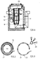
- Fig. 1
- a first embodiment, installed in a coalescence separator shown in vertical section.
- Fig. 2
- 1 in perspective representation,
- Fig. 3
- 2 shows a horizontal section according to III-III of FIG. 1,
- Fig. 4
- a second embodiment in the vertical axial section of the round separator tank,
- Fig. 5
- 4 shows a horizontal section according to VV of FIG. 4,
- Fig. 6
- a single turn of the flushing hose and a sleeve with 3 flushing nozzles,
- Fig. 7
- a rinsing insert equipped with rod-shaped rinsing tubes,
- Fig. 8
- a ring tube as a movable sink insert,
- Fig. 9
- a nozzle disc with detergent connection pipe,
- Fig. 10
- a backwashing device built into the coalescence insert, which consists of an upper distributor ring pipe, vertical nozzle pipes and several ring or half pipes.
- Fig. 11
- a cylinder bell with suction connection placed over the coalescence insert,
- Fig. 12
- a double-walled sink insert with closure for the clear water outlet.
- Fig. 13
- an embodiment with lifting and rotating coalescence insert,
- Fig. 14
- the top view of FIG. 13.
Aus Fig. 1 ist zu erkennen, daß es sich bei dem Abscheider um ein monolithisch, d.h. in einem Stück aus Stahlbeton hergestelltes Becken 1 handelt, das oben durch eine Decke 2 abgedeckt ist, welche ihrerseits eine Wartungsöffnung 3 und eine Schachtabdeckung 4 aufweist. Zu- und Ablaufstutzen 5, 6 sind flexibel durch Mauerflansche 7 geführt. Die Klarwasser-Auslaufarmatur 8 enthält an der Einlauföffnung einen Ventilsitz 9 für den nach DIN 1999 vorgeschriebenen Schwimmerverschluß 10, der auf die Dichtedifferenz zwischen Wasser und Leichtflüssigkeit tariert ist. Dem Ventilsitz 9 ist der hohlzylindrische Koaleszenzeinsatz 11 vorgeordnet, der auf den den Schwimmer 10 führenden Käfig 12 aufgesteckt ist.From Fig. 1 it can be seen that the separator is a monolithic, ie in one piece made of reinforced
Der Käfig 12 enthält gemäß Fig. 2 statt der Vertikalstäbe Rohre 13, die auf ihrer Länge mit radial nach außen gerichteten Düsen 14 ausgerüstet sind. Unten sind die Rohre 13 mit einem Verteiler-Ringrohr 15 verbunden, das einen Anschlußstutzen 16 für den Spülmittelschlauch 17 enthält. Der Spülmittelschlauch ist an der Wand des Abscheidebeckens verlegt. Die Schlauchkupplung 18 liegt leicht erreichbar im Wartungsschacht.According to FIG. 2, the
Fig. 3 zeigt den Rückspülvorgang durch Pfeile 19. Bei leerem oder vollem Abscheidebecken wird Spülmittel - Trinkwasser, Brauchwasser oder Luft - unter Druck zugeführt. Die Spülstrahlen lösen die Ablagerungen im Koaleszenzeinsatz und schwemmen sie nach außen. Nach dem Rückspülen sollte dem Spülschlamm Gelegenheit zum Trennen von Leicht- und Schwerstoffen gegeben werden. Wenn der Rückspülvorgang bei entleertem Abscheider vorgenommen wurde, kann der Spülschlamm anschließend ebenfalls abgesaugt und vorschriftsmäßig entsorgt werden.Fig. 3 shows the backwashing process by
Der Rückspüleinsatz 12 kann zu Wartungs- und Reperaturzwecken ebenfalls ausgebaut werden, nach dem der Koaleszenzeinsatz ausgebaut worden ist. Beide Bauteile können sogar miteinander verbunden und dann gemeinsam ausgebaut werden.The
Der Koaleszenzabscheider nach Fig. 4 ist identisch mit dem nach Fig. 1, weshalb auf seine Einzelheiten hier nicht mehr eingegangen wird. Der Käfig 12', der dem Schwimmerverschluß 10 als Führung und dem Koaleszenzeinsatz 11 als Halterung dient, besteht jedoch in herkömmlicher Weise aus massiven Rundstäben 13', die oben durch einen Ring 20 und unten durch den Ventilsitzring 9 zusammengehalten werden.
Auf den Käfig 12' ist in dem Zwischenraum zum etwas größeren Koaleszenzeinsatz 11 ein Schlauch 21 spiralig aufgewickelt. Der Schlauch besitzt nach Fig. 6 eine Vielzahl von Muffen 22, die die Spüldüsen 23 enthalten. Jede Muffe besitzt vorzugsweise drei Düsen, die das Rückspülmittel fächerförmig spreizen und damit einen größeren Flächenabschnitt erfassen. Käfig, Schlauch und Koaleszenzeinsatz werden vorteilhafterweise außerhalb des Abscheiders montiert und dann als Einheit eingebaut. Zur intensiven Reinigung außerhalb des Abscheiders ist es jedoch sinnvoll, nur den Koaleszenzeinsatz entnehmen zu können.The coalescence separator according to FIG. 4 is identical to that according to FIG. 1, which is why its details are no longer discussed here. The cage 12 ', which serves the
A
Die Figuren 7 bis 9 zeigen Rückspüleinrichtungen, die nur zum Rückspülen in den Koaleszenzeinsatz eingeführt werden. Diese Technik hat den Vorteil, daß mit einer solchen Einrichtung mehrere Koaleszenzabscheider bedient werden können. Allerdings ist der Rückspüleffekt davon abhängig, wie gründlich die Bedienungsperson die Rückspüleinrichtung über die Innenfläche des Koaleszenzeinsatzes bewegt. Die Rückspüleinrichtung nach Fig. 7 besteht aus vier vertikal stehenden Spülrohren 13'', die oben durch ein Verteilerkreuz 25 verbunden sind. In der Mitte des Verteilerkreuzes 25 ist der Spülmittelstutzen 26 angeschlossen. Dieser Stutzen dient gleichzeitig als Handhabe. An einer Kette 27 hängt eine Kalotte 28, die den Klarwasserauslauf während der Rückspülung verschließt, damit kein Spülschlamm in die Auslaufleitung gelangt. Die Spüleinrichtung nach Fig. 8 enthält ein einziges Ringrohr 33 und nach Fig. 9 eine Hohlscheibe 43 mit einem Kranz von Spüldüsen 34 (hier insbesondere in Schlitzform).FIGS. 7 to 9 show backwashing devices which are only introduced into the coalescing insert for backwashing. This technique has the advantage that several coalescence separators can be operated with such a device. However, the backwash effect depends on how thoroughly the operator moves the backwashing device over the inner surface of the coalescence insert. The backwashing device according to FIG. 7 consists of four
Bei der Rückspüleinrichtung nach Fig. 10 kann es sich um eine ständig eingebaute oder nur zum Rückspülen eingeführte Bauart handeln. Zusätzlich zu den in Fig. 2 gezeigten vertikalen Spülrohren 13 hat diese Spüleinrichtung mehrere Halbringrohre 45, die sich gegenüberliegen. Sie können auch in der Höhe gegeneinander versetzt sein, so daß beim Drehen der Rückspüleinrichtung eine größere Fläche des Koaleszenzeinsatzes überstrichen wird. Die Düsenrohre können auch als geschlossene Ringe 44 ausgebildet und dann schräg angeordnet sein.The backwashing device according to FIG. 10 can be of a permanently installed type or only introduced for backwashing. In addition to the
In dem Koaleszenzabscheider nach Fig. 11 ist während des Rückspülens eine hohlzylindrische Glocke 30 über den Koaleszenzeinsatz 11 gestülpt. Die Glocke enthält einen Absauganschluß 31, an den während des Rückspülens eine Saugpumpe angeschlossen ist. Dies kann z.B. die Pumpe des Entsorgungsfahrzeugs sein, die dann den Spülschlamm sofort abzieht. Durch das Absaugen wird der Rückspülvorgang aktiv unterstützt.In the coalescence separator according to FIG. 11, a hollow
Die Ausführungsform der Erfindung nach Fig. 12 enthält als Rückspüleinrichtung ein Doppelrohr 35, 36, dessen Hohlraum über ein Verteilrohr 37 mit Spülmittel versorgt wird. Das äußere Rohr 35 enthält über die Länge und den Umfang verteilt eine Vielzahl von Düsenlöchern oder -schlitzen. Diese Spüleinrichtung kann während des Abscheiderbetriebs nicht im Abscheider bleiben, weil es den Durchfluß des Abwassers durch den Koaleszenzeinsatz unmöglich machen würde.The embodiment of the invention according to FIG. 12 contains a
Das Ausführungsbeispiel nach den Figuren 13 und 14 unterscheidet sich von den vorbeschriebenen dadurch, daß nur eine feststehende Düsenreihe 53 vorgesehen ist, die Bestandteil des Innenkäfigs 12 ist und einen Schlauchanschluß 17 enthält. Zum Rückspülen wird die an einer Traverse 38 gelagerte Spindel 29 betätigt, die den Koaleszenzeinsatz 11 zunächst anhebt und dann dreht. Nach dem Rückspülen wird der Koaleszenzeinsatz wieder auf seinen Sitz abgesenkt.The exemplary embodiment according to FIGS. 13 and 14 differs from the ones described above in that only one fixed row of
Claims (14)
Priority Applications (2)
| Application Number | Priority Date | Filing Date | Title |
|---|---|---|---|
| DE4421498A DE4421498C2 (en) | 1993-11-26 | 1994-06-20 | Coalescence separator with backwashing device |
| EP94119576A EP0725040A1 (en) | 1994-06-20 | 1994-12-10 | Coalescence separator |
Applications Claiming Priority (2)
| Application Number | Priority Date | Filing Date | Title |
|---|---|---|---|
| DE4421498A DE4421498C2 (en) | 1993-11-26 | 1994-06-20 | Coalescence separator with backwashing device |
| EP94119576A EP0725040A1 (en) | 1994-06-20 | 1994-12-10 | Coalescence separator |
Publications (1)
| Publication Number | Publication Date |
|---|---|
| EP0725040A1 true EP0725040A1 (en) | 1996-08-07 |
Family
ID=25937559
Family Applications (1)
| Application Number | Title | Priority Date | Filing Date |
|---|---|---|---|
| EP94119576A Withdrawn EP0725040A1 (en) | 1993-11-26 | 1994-12-10 | Coalescence separator |
Country Status (1)
| Country | Link |
|---|---|
| EP (1) | EP0725040A1 (en) |
Cited By (1)
| Publication number | Priority date | Publication date | Assignee | Title |
|---|---|---|---|---|
| WO1999030796A1 (en) * | 1997-12-18 | 1999-06-24 | 'ar-Kal' Plastics Products (1973) | Reverse flow spin-cleaning liquid filters |
Citations (5)
| Publication number | Priority date | Publication date | Assignee | Title |
|---|---|---|---|---|
| US3511374A (en) * | 1968-11-01 | 1970-05-12 | California & Hawaiian Sugar Co | Screening device |
| EP0207797A2 (en) * | 1985-07-05 | 1987-01-07 | The British Petroleum Company p.l.c. | Expandable bed fibre filter and coalescer |
| DE9305559U1 (en) * | 1993-04-14 | 1993-07-01 | Passavant-Werke AG, 6209 Aarbergen | Coalescing separator |
| US5228993A (en) * | 1990-02-09 | 1993-07-20 | Mordeki Drori | Cleanable filter system with longitudinally movable and rotatable cleaning member |
| DE4337187C1 (en) * | 1993-10-30 | 1994-11-10 | Honeywell Ag | Backwashable filter device |
-
1994
- 1994-12-10 EP EP94119576A patent/EP0725040A1/en not_active Withdrawn
Patent Citations (5)
| Publication number | Priority date | Publication date | Assignee | Title |
|---|---|---|---|---|
| US3511374A (en) * | 1968-11-01 | 1970-05-12 | California & Hawaiian Sugar Co | Screening device |
| EP0207797A2 (en) * | 1985-07-05 | 1987-01-07 | The British Petroleum Company p.l.c. | Expandable bed fibre filter and coalescer |
| US5228993A (en) * | 1990-02-09 | 1993-07-20 | Mordeki Drori | Cleanable filter system with longitudinally movable and rotatable cleaning member |
| DE9305559U1 (en) * | 1993-04-14 | 1993-07-01 | Passavant-Werke AG, 6209 Aarbergen | Coalescing separator |
| DE4337187C1 (en) * | 1993-10-30 | 1994-11-10 | Honeywell Ag | Backwashable filter device |
Cited By (2)
| Publication number | Priority date | Publication date | Assignee | Title |
|---|---|---|---|---|
| WO1999030796A1 (en) * | 1997-12-18 | 1999-06-24 | 'ar-Kal' Plastics Products (1973) | Reverse flow spin-cleaning liquid filters |
| US6398037B1 (en) | 1997-12-18 | 2002-06-04 | “AR-KAL” Plastics Products | Reverse flow spin-cleaning liquid filters |
Similar Documents
| Publication | Publication Date | Title |
|---|---|---|
| DE3888522T2 (en) | DEVICE AND METHOD FOR FILTERING. | |
| DE4339268A1 (en) | Method and device for filtering and backwashing solid particles from liquids | |
| DE1761106C3 (en) | Filters for cleaning liquids mixed with solids | |
| DE19501034C2 (en) | Device for separating floating and suspended matter from a liquid | |
| DE2402250A1 (en) | DEVICE FOR UNMIXING A MIXING LIQUID USING DIFFERENT DENSITY VALUES | |
| DE3787097T2 (en) | METHOD AND DEVICE FOR SEPARATING SOLID PARTICLES FROM A LIQUID. | |
| DE19741827B4 (en) | Drain fitting for bath or shower trays | |
| DE4421498A1 (en) | Sepn. of water from lighter fluid deposits bearing heavy particles | |
| EP0725040A1 (en) | Coalescence separator | |
| EP0252996B1 (en) | Device for filtration of liquid | |
| CH675546A5 (en) | Domestic water tap filter - has sieve rotating while advancing past radial bristles to detach externally deposited solids for flushing | |
| EP1129756A2 (en) | Device for cleaning a cylindrical screen and rainwater purification equipment with cylindrical screen | |
| DE29505028U1 (en) | Sewage lifting station | |
| EP0768436B1 (en) | Device to separate solid substances from liquids, in particular gully, kit and cover for making the same and flushing- and suction pipe for its cleaning | |
| DE8116638U1 (en) | "SEPARATING AND CLEANING DEVICE FOR A LIQUID MIXTURE THAT CAN ALSO CONTAIN SOLIDS" | |
| DE9414485U1 (en) | Coalescence separator | |
| DE3341281A1 (en) | Liquid filter | |
| DE2635923C3 (en) | In-line valve | |
| DE8715672U1 (en) | Filling valve for liquid or pasty media | |
| DE102021001983B4 (en) | reusable separator for drainage systems | |
| DE29818962U1 (en) | Light liquid separator | |
| DE4118283C2 (en) | Process and device for filtering dirty water | |
| DE3332511A1 (en) | Filter, in particular for liquids | |
| DE29520958U1 (en) | Separation plant for wastewater loaded with floating and sinking substances | |
| DE19520861C2 (en) | Device for backwashing large area filters |
Legal Events
| Date | Code | Title | Description |
|---|---|---|---|
| PUAI | Public reference made under article 153(3) epc to a published international application that has entered the european phase |
Free format text: ORIGINAL CODE: 0009012 |
|
| AK | Designated contracting states |
Kind code of ref document: A1 Designated state(s): AT BE CH DE DK ES FR GB GR IE IT LI LU NL PT SE |
|
| 17P | Request for examination filed |
Effective date: 19961018 |
|
| 17Q | First examination report despatched |
Effective date: 19980807 |
|
| STAA | Information on the status of an ep patent application or granted ep patent |
Free format text: STATUS: THE APPLICATION IS DEEMED TO BE WITHDRAWN |
|
| 18D | Application deemed to be withdrawn |
Effective date: 19981218 |