EP0723129A2 - Schmelzverfahren für Lichtbogenofen mit verschiedenen Energiequellen und Lichtbogen dafür - Google Patents
Schmelzverfahren für Lichtbogenofen mit verschiedenen Energiequellen und Lichtbogen dafür Download PDFInfo
- Publication number
- EP0723129A2 EP0723129A2 EP95120399A EP95120399A EP0723129A2 EP 0723129 A2 EP0723129 A2 EP 0723129A2 EP 95120399 A EP95120399 A EP 95120399A EP 95120399 A EP95120399 A EP 95120399A EP 0723129 A2 EP0723129 A2 EP 0723129A2
- Authority
- EP
- European Patent Office
- Prior art keywords
- oxygen
- furnace
- lance
- coal dust
- tuyéres
- Prior art date
- Legal status (The legal status is an assumption and is not a legal conclusion. Google has not performed a legal analysis and makes no representation as to the accuracy of the status listed.)
- Granted
Links
Images


Classifications
-
- F—MECHANICAL ENGINEERING; LIGHTING; HEATING; WEAPONS; BLASTING
- F27—FURNACES; KILNS; OVENS; RETORTS
- F27B—FURNACES, KILNS, OVENS OR RETORTS IN GENERAL; OPEN SINTERING OR LIKE APPARATUS
- F27B3/00—Hearth-type furnaces, e.g. of reverberatory type; Electric arc furnaces ; Tank furnaces
- F27B3/10—Details, accessories or equipment, e.g. dust-collectors, specially adapted for hearth-type furnaces
- F27B3/22—Arrangements of air or gas supply devices
- F27B3/225—Oxygen blowing
-
- C—CHEMISTRY; METALLURGY
- C21—METALLURGY OF IRON
- C21C—PROCESSING OF PIG-IRON, e.g. REFINING, MANUFACTURE OF WROUGHT-IRON OR STEEL; TREATMENT IN MOLTEN STATE OF FERROUS ALLOYS
- C21C5/00—Manufacture of carbon-steel, e.g. plain mild steel, medium carbon steel or cast steel or stainless steel
- C21C5/52—Manufacture of steel in electric furnaces
- C21C5/5211—Manufacture of steel in electric furnaces in an alternating current [AC] electric arc furnace
- C21C5/5217—Manufacture of steel in electric furnaces in an alternating current [AC] electric arc furnace equipped with burners or devices for injecting gas, i.e. oxygen, or pulverulent materials into the furnace
-
- F—MECHANICAL ENGINEERING; LIGHTING; HEATING; WEAPONS; BLASTING
- F27—FURNACES; KILNS; OVENS; RETORTS
- F27B—FURNACES, KILNS, OVENS OR RETORTS IN GENERAL; OPEN SINTERING OR LIKE APPARATUS
- F27B3/00—Hearth-type furnaces, e.g. of reverberatory type; Electric arc furnaces ; Tank furnaces
- F27B3/10—Details, accessories or equipment, e.g. dust-collectors, specially adapted for hearth-type furnaces
- F27B3/20—Arrangements of heating devices
- F27B3/205—Burners
-
- Y—GENERAL TAGGING OF NEW TECHNOLOGICAL DEVELOPMENTS; GENERAL TAGGING OF CROSS-SECTIONAL TECHNOLOGIES SPANNING OVER SEVERAL SECTIONS OF THE IPC; TECHNICAL SUBJECTS COVERED BY FORMER USPC CROSS-REFERENCE ART COLLECTIONS [XRACs] AND DIGESTS
- Y02—TECHNOLOGIES OR APPLICATIONS FOR MITIGATION OR ADAPTATION AGAINST CLIMATE CHANGE
- Y02P—CLIMATE CHANGE MITIGATION TECHNOLOGIES IN THE PRODUCTION OR PROCESSING OF GOODS
- Y02P10/00—Technologies related to metal processing
- Y02P10/20—Recycling
Definitions
- This invention concerns a melting method for an electric arc furnace with alternative sources of energy and the relative electric arc furnace, as set forth in the respective main claims.
- This invention is applied to the field of electric arc furnaces for the melting of iron-based alloys and has been conceived and designed to optimise the efficiency and output of a plant by using alternative sources of energy.
- This invention aims to achieve a saving of electrical energy during the melting cycle and to reduce the cycle times by increasing the number of castings which can be achieved per day; moreover, the invention tends to increase the yield factor of the alternative energy introduced.
- the invention is applied both to furnaces working with direct current and to furnaces working with alternating current.
- the furnaces to which the invention is applied can have a tapping channel or a tap hole without any constraint regarding the positioning of the hole.
- a typical and preferred, but not exclusive, application of the invention is its use in furnaces which are caused to work with the "pond” method, that is to say, with a liquid heel always present.
- the invention is also suitable for the melting of completely cold charges.
- the invention is applied both to furnace charges of scrap in skips or continuous charges of scrap or to continuous charges of pre-reduced material or to mixed charges.
- the state of the art of methods for melting metals contains the procedure of injecting into the furnace gaseous elements based on oxygen, possibly in combination with carbonaceous fuels, to obtain a reaction of oxidation with those fuels and with the oxidisable chemical elements included in the molten metallic mass and in the scrap.
- These gaseous elements with an oxygen base which are injected may consist of air, air enriched with oxygen or even of pure oxygen.
- gaseous elements can be blown onto the molten metal by means of lances located above the surface of the bath and/or by means of nozzles or tuyéres positioned in the hearth of the furnace.
- burners act along a circumference positioned between the electrodes and the sidewall of the furnace, and their method of working is with the action of one burner working as a support for the action of the next one so as to create a vortex in the empty part of the furnace.
- GB-A-2,115,011 teaches the blowing of the stirring and conversion gas from below the bath of molten metal.
- GB-A-1,421,203 teaches the delivery of oxygen or other gases from the bottom into a zone between the electrodes and the sidewall of the furnace.
- FR-B-2.208.988 teaches the delivery of gas into the furnace from above downwards and also teaches the delivery of gas from below the scrap and/or bath of molten metal both in the zone of the electrodes and between the electrodes and the sidewall of the furnace.
- This document includes, next, in the sidewall one or more lances which deliver oxygen and/or other gases, in a configuration such that the action of one lance acts as a support for the action of the next one, between the electrodes and the sidewall of the furnace, the purpose being to create a great mixing of the gases in the empty part of the furnace.
- EP-B1-257.450 discloses a method whereby a plurality of lances are used which deliver oxygen or mixtures of oxygen between the electrodes and the inner sidewalls of the furnace, and whereby a plurality of nozzles are used which are arranged below the molten bath and in the zones where the lances work.
- nozzles positioned on the bottom are employed also to stir the bath and to make uniform the blowing action of the lances inasmuch as, even when lances of a supersonic type are used, the jet of the combustion gases cannot reach a depth greater than 20 to 30 cms. in the molten bath unless expendable lances are used.
- the nozzles and tuyéres of the state of the art function typically with pressures up to 60 bar, but normally between 5 and 20 bar.
- these nozzles or tuyéres on the bottom have an oxygen emission diameter between 3 and 6 mm. and consist advantageously of a double tube, with a central tube to emit O 2 and an annular surrounding slit to emit hydrocarbons and/or inert gases for cooling purposes.
- tuyéres to blow oxygen from the bottom, combined, for instance, with different fluids such as argon, nitrogen and methane, enables the oxidation reaction to be improved and made uniform.
- This method entails a swift passage of the oxygen through the bath of molten metal, this oxygen being mostly burnt in the empty part of the furnace up to the roof of the furnace.
- the adjustment of the blowing during the various working cycles is carried out on the flow rate of the gases, and the pressure is variable as a fact resulting from the variation of the flow rate.
- the tuyéres are placed substantially symmetrically on the hearth of the furnace, often in a position corresponding to that of the oxygen emission lances, which are located, moreover, in the high part of the furnace.
- This invention employs in an innovatory manner the technology of the tuyéres and the blowing devices for the injection of gases and fuels into the furnace.
- This injection of oxygen and fuels based on carbon has the purpose of causing a quick start-up of the exothermic chemical reactions of re-combination, by oxidation, of the chemical elements in the molten bath immediately above the bath and in the scrap during the progress of the melting.
- this injection of oxygen and fuels is carried out in such a way as to increase the surface area affected by the reaction so as to obtain a wide direct distribution of the heat, a considerable reduction of the consumption of electrical energy and a reduction of the times of melting of the charge.
- the production cycle according to this invention can be applied to any type of charge even if, as an example, we shall dwell in this description substantially on three types of starting material to arrive at the molten steel.
- the first type of example of a starting material provides for the use of scrap alone by charging the furnace with a plurality of charges, that is to say, by introducing the desired quantity of scrap into the furnace in a plurality of steps; in the cases considered hereinafter, the number of charges is typically two.
- the second type of example of the starting material provides for a mixture of scrap and molten cast iron in desired percentages and advantageously with alternate charges, namely typically one charge of scrap, one charge of molten cast iron and a successive charge of scrap.
- the third type of example of the starting material provides for a mixture of scrap and sponge-iron (pre-reduced iron) in desired percentages, advantageously with a first single charge of scrap together with a quantity of sponge-iron and a successive continuous charging of the remaining quantity of sponge-iron.
- the invention provides for the injection into the furnace of:
- the supersonic lances or the tuyéres delivering coal dust, or both may be of a type with a fixed position or may be of a type which can be moved, actuated and positioned as desired either directly or by means of remote controls.
- the invention tends to produce induced and controlled chemical reactions in a very specific zone of the furnace so as to make maximum use of the energy potential of the individual elements and, in particular, of the post-combustion phenomenon with a great effectiveness from the energy point of view towards the bath of molten metal.
- the invention tends to induce and enhance a plurality of chemical reactions within the molten bath in the layer of slag and just above that layer of slag.
- the oxygen injected from the bottom by the oxygen tuyéres rises from the bottom according to a wide cone of dispersion and reacts mostly with the Fe in the molten metal to create FeO , which re-combines with the C coming from the charge and present in the bath.
- This re-combination frees the Fe and generates CO , which tends to rise above the molten metal into the slag.
- the oxygen delivered by the supersonic lance and entering in depth into the bath reacts with the Fe to cause substantially the same reaction as that generated by oxygen from the oxygen tuyéres.
- the supersonic lance sends the oxygen in the same direction as the direction of rotation of the molten bath, so that there take place a distribution of the heat produced and a homogenisation over the whole surface of the bath.
- the carbonaceous substances delivered by the tuyéres delivering the coal dust reduce the excess of FeO and generate CO , which contributes to the desired formation of foamy slag.
- the lance delivering coal dust together with the supersonic oxygen lance causes a strongly reducing zone above the layer of slag, and owing to the rotation of the slag this reducing zone is distributed into an area heavily sprinkled with oxygen, thus contributing to the formation of further CO , which increases the foamy conformation of the slag.
- the oxygen delivered by the burners involves the CO in the foamy slag and the CO emerging from that slag, thus generating a post-combustion reaction with a strong delivery of heat in close proximity to the foamy slag.
- This foamy slag causes the transfer of the greater part of that heat to the molten metal.
- blowing devices work substantially at the central zone of the furnace.
- a first group of these blowing devices acts at a tangent to a ring defined by a first outer circumference, which has a maximum value of about 0.70 times the upper inner diameter of the furnace defined at the cooled panels, and by a second inner circumference, which has a minimum value of about 0.25 times the upper inner diameter of the furnace.
- a second group of these blowing devices acts directly towards the centre of the furnace.
- This orientation of the blowing devices has the result of making uniform and homogeneous the transfer of thermal energy to the whole mass of molten metal without causing the problems of wear, which arise in the state of the art when the jets of the blowing devices work close to or against the refractory sidewalls of the furnace, against the electrodes and against the roof of the furnace, or when the post-combustion takes place in the free space of the furnace.
- the melting method according to the invention can be divided substantially into at least two separate steps which characterise each single cycle of charging the material, plus a third step which takes place when the charge has been melted.
- the first step corresponds to the charging of the furnace and to the start-up of the melting of the charge. This first step requires a great contribution of energy to start the melting of the charge, particularly when the charge is cold.
- the first step is characterised by an accentuated use of the burners in their specific function, that is to say, in this first step the burners inject oxygen and a fuel, generally methane, to prime a reaction of combustion which generates a huge quantity of heat.
- At least one burner is employed in contributing to the speedy freeing from scrap of the zone in front of the supersonic lance and the lance delivering coal dust, the purpose of this being to free the space required for introduction of those lances into the furnace so that they can be quickly put to work.
- this burner affects a zone which would otherwise be a cold zone.
- the oxygen tuyéres deliver oxidising gas from the bottom at high rates of flow and at a low pressure.
- This pressure of the oxygen may be constant or continuously variable or variable in one or more steps.
- the emission of the oxygen by the supersonic lances takes place not at once but when a minimum head of molten metal is present and the whole relative zone is free of scrap.
- the second step concerns the completion of the melting of the charge.
- the pressure of blowing the oxygen from the oxygen tuyéres may be constant or may be increased progressively (as said above, continuously or according to one or more steps) so as to supply also a greater quantity of oxygen according to the requirements of the bath.
- the rate of flow of the oxygen in the oxygen tuyéres, at least in the first and second melting steps, may vary between a minimum value of about 2.8 Nm 3 /min . per each single oxygen tuyére and a maximum value of about 6.0 Nm 3 /min .
- the low blowing pressure at which the oxygen is delivered does not create problems of spurting of the molten steel and, above all, does not create problems of the thermal lance type with a resulting perforation of the roof.
- the positioning and orientation of the subsonic oxygen lances are such as to ensure a wide effect of covering the surface of the slag, bearing in mind also the convective motions of the molten bath and of the slag on a substantially horizontal plane.
- the third step in the method is the refining step.
- the tuyéres on the bottom are kept working with a minimum blowing pressure of about 3 to 4 bar and with a minimum flow rate of 1.5 to 1.8 Nm 3 /min ., with possibly only inert gases being blown in.
- This minimum pressure is the pressure enough to overcome the ferrostatic pressure of the liquid heel and to withstand the dynamic action which the charge exerts on the molten metal at the moment of its introduction.
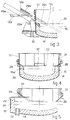
- An electric arc furnace 10 shown in Figs.1 to 5 comprises in this case three upper electrodes 11, 11a, 11b and 11c respectively for generation of the electric arc.
- the electric arc furnace 10 is equipped with oxygen tuyéres 13, four in number in this case and positioned in the hearth 14.
- the oxygen tuyéres 13 are positioned within a ring which surrounds a circle 34 enclosing the electrodes 11 and is outside that circle 34.
- the ring which, depending on the structure of the hearth 14 of the furnace 10, may be circular or may have another similar configuration, is defined by an outer perimeter and an inner perimeter.
- the outer perimeter is defined by a diameter which is advantageously about 0.5 to 0.7 times the upper inner diameter defined in the high part of the furnace 10 which includes the cooled panels 31, whereas the inner perimeter is defined by a diameter which is advantageously about 0.25 to 0.35 times that upper inner diameter.
- the vertical axis of the oxygen tuyére 13 in relation to the closest vertical refractory sidewall 30 has to be distant from that sidewall 30 by a value between at least 0.7 and 1.4 times the height of the liquid head at the specific oxygen tuyére 13.
- the oxygen tuyéres 13 are arranged substantially along a circumference equal to about 0.55 times the upper inner diameter and are located in the front semi-circle of the hearth 14 toward the tap hole 32.
- This semi-circle is defined by the vertical plane positioned perpendicular to the longitudinal vertical plane which passes through the tap hole 32 and through the central axis of the furnace 10.
- At least one oxygen tuyére 13 is included in a position of substantial cooperation with a hole 36 for the aspiration of fumes located in the roof of the furnace 10 and shown with lines of dashes in Fig.1;
- the oxygen tuyéres 13 include a central pipe 18 to deliver oxygen, this pipe being provided by means of a bore in a polygonal copper section 19.
- This polygonal copper section 19 is surrounded by a cylindrical pipe 20 so as to create a plurality of sectors 21 between each side 17 of the polygonal copper section 19 and the inner circumference of the cylindrical pipe 20.
- the sectors 21 form passages for the gaseous cooling mixture.
- the central pipe 18 to deliver oxygen advantageously has a diameter between 10 and 20 mm., but preferably between 10 and 14 mm.
- the cooling mixture passing through the sectors 21 consists of at least one gas of a high cooling power, methane in this case, and of a diluting or filling gas, CO 2 in this case, or else N 2 or a mixture of these gases.
- CO 2 is indicated as the diluting gas but the conditions of CO 2 , N 2 gases or a mixture shall be understood as being included.
- Fig.10 shows with a block diagram the system for immediate adjustment of the percentages of these components of the cooling mixture.
- the adjustment of the percentages is carried out so as to keep unchanged, or substantially unchanged, the ratio between the quantity of cooling gas in the mixture and the flow rate of the oxygen, with a value determined beforehand as being indispensable for ensuring the necessary and desired cooling of the oxygen tuyéres 13.
- the primary adjustment takes place, by means of an adjustment circuit 27, on the pressure of the oxygen injected through the central delivery pipe 18 of the oxygen tuyéres 13.
- This adjustment of pressure affects the flow rate of the oxygen, this flow rate being read continuously by a flow rate reader 23 and being sent to an adjuster 24.
- This adjuster 24 acts on a valve 25 located on the feed line of CO 2 so as to vary the pressure of the same.
- Variation of the pressure of the CO 2 causes a corresponding variation of the rate of flow of the CO 2 , this variation of the rate of flow being compensated in a mixer 26 by a variation of the CH 4 .
- the minimum rate of flow of oxidising gas in the melting steps in each of the oxygen tuyéres 13 is about 2.8 Nm 3 /min. , whereas the maximum rate of flow may reach about 6.0 Nm 3 /min. .
- the blowing pressure is kept at about 3 to 4 bar, with minimum rates of flow of about 1.5 to 1.8 Nm 3 /min ..
- the blowing pressure may be the same in all the oxygen tuyéres 13 or may be a characteristic pressure for each oxygen tuyére 13 according to the relative position thereof.
- This pressure is never greater than 10 bar, as measured at the inlet of the oxygen tuyéres 13, for a height of the bath of molten metal from 0.7 to 1.1 metres on the vertical plane of the oxygen tuyére 13.
- a supersonic lance 12 combined with a coal dust lance 29 is included to blow the oxygen within the molten bath 16 and thereabove.
- the supersonic lance 12 and the coal dust lance 29 work in the area in front of the door 35 of the furnace 10; these lances 12 and 29 work, moreover, at a tangent to a circumference within the circle 34 containing the electrodes 11 and work in the same direction as the direction of rotation of the bath 16 of molten metal and of the slag 22.
- the supersonic lance 12 and the coal dust lance 29 have respective first inactive positions 12a, 29a outside the furnace 10, second respective waiting positions 12b, 29b outside the furnace 10 and respective third working positions 12c, 29c within the furnace 10.
- the supersonic lance 12 and coal dust lance 29 are inclined towards the bath 16 of molten metal by an angle of about 30° to the horizontal; the supersonic lance 12 has its outlet in close proximity to the surface of the bath 16 of molten metal, whereas the coal dust lance 29 has its outlet in close proximity to the surface of the layer of slag 22.
- the supersonic lance 12 delivers the oxygen onto the bath 16 of molten metal at an angle between 40° and 50°, but advantageously 45°, to the horizontal.
- the supersonic lance 12 injects the oxygen into the bath 16 of molten metal through one single outlet hole with a very carefully oriented jet, thus defining an area 33a on the surface of the bath 16 of molten metal; the part of the oxygen injected by the supersonic lance 12 which does not combine with the Fe emerges in an area 33b located generally within the circle 34 surrounding the electrodes 11.
- the supersonic lance 12 is oriented so as to work in the bath 16 of molten metal in an area not equipped with oxygen tuyéres 13.
- Tuyéres 15 to deliver coal dust which in this case are two in number (Fig.1), are included in cooperation with the refractory sidewalls 30 substantially at the level of the layer of slag 22.
- coal dust tuyéres 15 consist advantageously of replaceable ceramic-coated pipes, are generally installed immovably and have the function of delivering the carbonaceous substances onto the molten bath 16 below the layer of slag 22.
- coal dust tuyéres 15 face towards the centre of the furnace 10 and are fitted in a substantially horizontal position (15a, Fig.4).
- the coal dust tuyéres 15 (15b, Fig.3) are inclined downwards by an angle between about 30° and 45° to the horizontal.
- coal dust tuyéres 15 cooperates with the supersonic lance 12 in delivering carbonaceous substances below the slag 22.
- the other coal dust tuyére 15 cooperates with a zone located at the side of the tap hole 32 in an area heavily sprinkled with the oxygen arriving from the oxygen tuyéres 13.
- Burners 28 are installed, according to the invention, on the cooled sidewalls 31 of the furnace 10 and act downwards from above and are inclined to the horizontal by an angle between 20° and 45°.
- the burners 28 emit oxygen at a subsonic speed.
- burners 28 there are six burners 28, of which two burners 28a, 28b are oriented towards the centre of the furnace 10 so as to cooperate, in the first melting step, with the electrodes 11 and, in the second melting step, with the carbonaceous substances delivered by the coal dust tuyéres 15 and with the oxygen delivered by the oxygen tuyéres 13.
- the burner 28e in this case, which collaborates also in freeing the path of the supersonic lance 12 so that the latter can be quickly put in its working position 12c.
- This burner 28e has also the task of delivering and making uniform the heat on the scrap in the zone in front of the door 35 of the furnace 10, for this zone would otherwise be cold.
- the other burners 28c, 28d, 28f are arranged according to a configuration whereby the action of one burner works as a support for the action of the next one and the burners direct their jets in a direction substantially at a tangent to a plurality of circumferences.
- burners 28f, 28c work in surface zones which are positioned on the vertical plane of the oxygen tuyéres 13, whereas the other burners 28d and, partly, 28e, have the purpose of conveying the heat and combining it so as to complete the action of one burner working as a support for the action of the next one.
- the circumferences along which the burners 28 work are outside the circle 34 of the electrodes 11 and have a diameter substantially between 0.25 and 0.70 times the upper inner diameter of the electric arc furnace 10 so as to affect a ring which coincides substantially with the ring of positioning of the oxygen tuyéres 13.
- the burners 28c-28f act in a direction the same as the normal direction of rotation of the bath 16 of molten metal and of the layer of slag 22 during the melting process.
- the burners 28 work in the direction contrary to the working of the supersonic oxygen lance 12 and of the coal dust lance 29, the burners 28c-28f act in the opposite direction to the direction of rotation of the molten bath 16 and of the layer of slag 22.
- the burners 28 have an outlet equipped with a number of holes from six to ten for delivery of oxygen.
- Fig.6 shows the case of application of charging of the furnace with only scrap in two separate charges
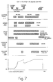
- Fig.7 shows the case of charging with scrap and molten cast iron with a first charge of scrap, a charge of molten cast iron and a second charge of scrap
- Fig.8 shows the case of charging with scrap and sponge iron with a first mixed charge of scrap/sponge iron and a second charge with sponge iron only.
- the first two cases show also a precise step of refining, which follows the step of melting of the metal, whereas in the third case the refining step is continuous.
- the percentage of molten metal as compared to the total of metal within the electric arc furnace 10 has reached a significant value, and this situation entails a reduction of the transfer of heat from the burners 28 to the scrap and molten metal and therefore an appreciable reduction of the efficiency of the burners 28.
Landscapes
- Engineering & Computer Science (AREA)
- Chemical & Material Sciences (AREA)
- Mechanical Engineering (AREA)
- General Engineering & Computer Science (AREA)
- Metallurgy (AREA)
- Materials Engineering (AREA)
- Manufacturing & Machinery (AREA)
- Organic Chemistry (AREA)
- Vertical, Hearth, Or Arc Furnaces (AREA)
- Refinement Of Pig-Iron, Manufacture Of Cast Iron, And Steel Manufacture Other Than In Revolving Furnaces (AREA)
- Waste-Gas Treatment And Other Accessory Devices For Furnaces (AREA)
- Furnace Details (AREA)
- Discharge Heating (AREA)
Applications Claiming Priority (2)
| Application Number | Priority Date | Filing Date | Title |
|---|---|---|---|
| IT95UD000003A IT1280115B1 (it) | 1995-01-17 | 1995-01-17 | Procedimento di fusione per forno elettrico ad arco con sorgenti alternative di energia e relativo forno elettrico ad arco |
| ITUD950003 | 1995-01-17 |
Publications (3)
| Publication Number | Publication Date |
|---|---|
| EP0723129A2 true EP0723129A2 (de) | 1996-07-24 |
| EP0723129A3 EP0723129A3 (de) | 1996-11-06 |
| EP0723129B1 EP0723129B1 (de) | 2002-04-17 |
Family
ID=11421697
Family Applications (1)
| Application Number | Title | Priority Date | Filing Date |
|---|---|---|---|
| EP95120399A Expired - Lifetime EP0723129B1 (de) | 1995-01-17 | 1995-12-22 | Schmelzverfahren für Lichtbogenofen mit verschiedenen Energiequellen und Lichtbogen dafür |
Country Status (12)
| Country | Link |
|---|---|
| US (1) | US5802097A (de) |
| EP (1) | EP0723129B1 (de) |
| CN (1) | CN1145469A (de) |
| AT (1) | ATE216483T1 (de) |
| BR (1) | BR9600458A (de) |
| CA (1) | CA2167140A1 (de) |
| DE (1) | DE69526422T2 (de) |
| ES (1) | ES2174894T3 (de) |
| IN (1) | IN186479B (de) |
| IT (1) | IT1280115B1 (de) |
| PL (1) | PL312321A1 (de) |
| ZA (1) | ZA9683B (de) |
Cited By (6)
| Publication number | Priority date | Publication date | Assignee | Title |
|---|---|---|---|---|
| DE19707319C1 (de) * | 1997-02-12 | 1998-06-18 | Mannesmann Ag | Verfahren und Einrichtung zum Positionieren der Mündung einer verzehrbaren Lanze |
| WO1998048228A1 (fr) * | 1997-04-24 | 1998-10-29 | Paul Wurth S.A. | Procede de fusion d'alliages a base de fer dans un four electrique |
| TR199802756A3 (tr) * | 1997-12-30 | 1999-11-22 | S.A. White Martins | Çelik üretiminde elektrik arkli firinlara yapilan oksijen enjeksiyonuna iliskin yöntemler. |
| EP1050590A1 (de) * | 1999-05-07 | 2000-11-08 | L'air Liquide, Societe Anonyme Pour L'etude Et L'exploitation Des Procedes Georges Claude | Lichtbogenofen zur Stahlherstellung sowie Betriebsverfahren dafür |
| EP1114192A4 (de) * | 1998-08-28 | 2003-06-25 | Tech Resources Pty Ltd | Verfahren und vorrichtung zur herstellung von metallen und metalllegierungen |
| US7597736B2 (en) * | 2003-05-16 | 2009-10-06 | Siemens Vai Metals Technologies Gmbh & Co | Method for utilizing slag |
Families Citing this family (40)
| Publication number | Priority date | Publication date | Assignee | Title |
|---|---|---|---|---|
| AUPN226095A0 (en) | 1995-04-07 | 1995-05-04 | Technological Resources Pty Limited | A method of producing metals and metal alloys |
| AUPO426096A0 (en) | 1996-12-18 | 1997-01-23 | Technological Resources Pty Limited | Method and apparatus for producing metals and metal alloys |
| AUPO426396A0 (en) | 1996-12-18 | 1997-01-23 | Technological Resources Pty Limited | A method of producing iron |
| AUPO944697A0 (en) * | 1997-09-26 | 1997-10-16 | Technological Resources Pty Limited | A method of producing metals and metal alloys |
| IT1299725B1 (it) * | 1998-01-23 | 2000-04-04 | Danieli Off Mecc | Procedimento di alimentazione per tubiere per forno elettrico e relativo dispostivo di alimentazione |
| US5999557A (en) * | 1998-06-19 | 1999-12-07 | The Broken Hill Proprietary Company | Steel making bath control |
| AUPP442598A0 (en) | 1998-07-01 | 1998-07-23 | Technological Resources Pty Limited | Direct smelting vessel |
| MY119760A (en) | 1998-07-24 | 2005-07-29 | Tech Resources Pty Ltd | A direct smelting process |
| AUPP483898A0 (en) | 1998-07-24 | 1998-08-13 | Technological Resources Pty Limited | A direct smelting process & apparatus |
| AUPP570098A0 (en) | 1998-09-04 | 1998-10-01 | Technological Resources Pty Limited | A direct smelting process |
| AUPP647198A0 (en) | 1998-10-14 | 1998-11-05 | Technological Resources Pty Limited | A process and an apparatus for producing metals and metal alloys |
| AUPP805599A0 (en) | 1999-01-08 | 1999-02-04 | Technological Resources Pty Limited | A direct smelting process |
| AUPQ083599A0 (en) | 1999-06-08 | 1999-07-01 | Technological Resources Pty Limited | Direct smelting vessel |
| AUPQ152299A0 (en) | 1999-07-09 | 1999-08-05 | Technological Resources Pty Limited | Start-up procedure for direct smelting process |
| AUPQ205799A0 (en) | 1999-08-05 | 1999-08-26 | Technological Resources Pty Limited | A direct smelting process |
| AUPQ213099A0 (en) | 1999-08-10 | 1999-09-02 | Technological Resources Pty Limited | Pressure control |
| AUPQ308799A0 (en) | 1999-09-27 | 1999-10-21 | Technological Resources Pty Limited | A direct smelting process |
| AUPQ346399A0 (en) | 1999-10-15 | 1999-11-11 | Technological Resources Pty Limited | Stable idle procedure |
| AUPQ365799A0 (en) | 1999-10-26 | 1999-11-18 | Technological Resources Pty Limited | A direct smelting apparatus and process |
| US6614831B2 (en) * | 2000-02-10 | 2003-09-02 | Process Technology International, Inc. | Mounting arrangement for auxiliary burner or lance |
| US6602321B2 (en) | 2000-09-26 | 2003-08-05 | Technological Resources Pty. Ltd. | Direct smelting process |
| DE10240116A1 (de) * | 2002-08-30 | 2004-03-11 | Advanced Micro Devices, Inc., Sunnyvale | Verfahren zur Herstellung lokaler Verbindungsbarrierenschichten |
| US6999495B2 (en) | 2002-12-19 | 2006-02-14 | Air Liquide America, Lp | Method and apparatus for spatial energy coverage |
| US7951325B2 (en) * | 2006-05-17 | 2011-05-31 | Air Liquide Advanced Technologies U.S. Llc | Methods of implementing a water-cooling system into a burner panel and related apparatuses |
| US7824604B2 (en) | 2006-05-17 | 2010-11-02 | Air Liquide Advanced Technologies U.S. Llc | Methods of implementing a water-cooling system into a burner panel and related apparatuses |
| WO2009120858A1 (en) * | 2008-03-28 | 2009-10-01 | L'air Liquide Societe Anonyme Pour L'etude Et L' Exploitation Des Procedes | Burner/injector panel apparatus |
| US8042602B2 (en) * | 2009-06-16 | 2011-10-25 | Nucor Corporation | High efficiency plant for making steel |
| US20120224601A1 (en) | 2011-03-01 | 2012-09-06 | Air Liquide Advanced Technologies U.S. Llc | Burner and/or injector panel apparatus, methods of installation and use of the same in a metal-melting furnace, and metal-melting furnace including the same |
| US20130095437A1 (en) * | 2011-04-05 | 2013-04-18 | Air Products And Chemicals, Inc. | Oxy-Fuel Furnace and Method of Heating Material in an Oxy-Fuel Furnace |
| CN102618693A (zh) * | 2012-04-24 | 2012-08-01 | 中冶赛迪工程技术股份有限公司 | 偏心出钢侧顶连续加料的密闭电炉炉体 |
| US9068779B2 (en) | 2013-03-15 | 2015-06-30 | L'Air Liquide SociétéAnonyme Pour L 'Étude Et L Eploitation Des Procedes Georges Claude | Water-cooled burner and/or injector panel kits, water-cooled burner and/or injector panel apparatus, and methods of using the same |
| ITUD20130052A1 (it) * | 2013-04-23 | 2014-10-24 | Danieli Off Mecc | Procedimento per la fusione di materiale metallico in un impianto di fusione e relativo impianto di fusione |
| CN104848682B (zh) * | 2015-05-11 | 2018-04-13 | 中国恩菲工程技术有限公司 | 熔池熔炼炉 |
| CN106119543B (zh) * | 2016-07-01 | 2019-03-08 | 北京中凯宏德科技有限公司 | 冶金电炉及熔炼方法 |
| CN106367558A (zh) * | 2016-10-11 | 2017-02-01 | 马鞍山钢铁股份有限公司 | 一种电弧炉氧枪结构 |
| CN113710819B (zh) * | 2019-04-22 | 2022-08-16 | 日本制铁株式会社 | 含铬铁液的制造方法 |
| DE102020215147A1 (de) | 2020-12-01 | 2022-06-02 | Sms Group Gmbh | Verfahren zum pyrometallurgischen Einschmelzen von metallhaltigen Rohstoffen, Reststoffen und/oder Sekundärreststoffen |
| DE102020215140A1 (de) | 2020-12-01 | 2022-06-02 | Sms Group Gmbh | Verfahren und Einschmelzaggregat zum pyrometallurgischen Einschmelzen von metallhaltigen Rohstoffen, Reststoffen und/oder Sekundärreststoffen |
| US12497668B2 (en) | 2022-03-11 | 2025-12-16 | Midrex Technologies, Inc. | Hot metal production from DRI with electric arc heating |
| EP4563711A4 (de) * | 2022-08-18 | 2026-02-18 | Jfe Steel Corp | Verfahren zur denitrifikation von geschmolzenem stahl |
Family Cites Families (10)
| Publication number | Priority date | Publication date | Assignee | Title |
|---|---|---|---|---|
| US3459867A (en) * | 1967-08-10 | 1969-08-05 | Air Reduction | Direct arc furnace |
| DE2160999A1 (de) * | 1971-12-09 | 1973-06-28 | Maximilianshuette Eisenwerk | Duese zum einleiten von sauerstoff mit einem schutzmedium in konvertergefaesse |
| US3902889A (en) * | 1972-11-30 | 1975-09-02 | United States Steel Corp | Electric arc melting furnace |
| US3980802A (en) * | 1973-10-24 | 1976-09-14 | Paton Boris E | Method of arc control in plasma arc furnace torches |
| DE3629055A1 (de) * | 1986-08-27 | 1988-03-03 | Kloeckner Cra Tech | Verfahren zum gesteigerten energieeinbringen in elektrolichtbogenoefen |
| DE3806977A1 (de) * | 1988-03-03 | 1989-09-14 | Fuchs Systemtechnik Gmbh | Verfahren zum regeln des durchflusses beim einblasen eines gases durch einen bodenspuelstein waehrend des einschmelzens von metallen |
| GB9126068D0 (en) * | 1991-12-07 | 1992-02-05 | Air Prod & Chem | Tuyere for installation in hearth of electric arc furnace |
| EP0625685B1 (de) * | 1993-05-17 | 1999-07-21 | DANIELI & C. OFFICINE MECCANICHE S.p.A. | Lichtbogenofen mit verschiedenen Energiequellen und Verfahren für seinem Betrieb |
| ATA155793A (de) * | 1993-08-04 | 1996-04-15 | Voest Alpine Ind Anlagen | Verfahren zum herstellen einer metallschmelze und anlage zur durchführung des verfahrens |
| JPH07145420A (ja) * | 1993-09-30 | 1995-06-06 | Ishikawajima Harima Heavy Ind Co Ltd | 電気アーク溶解炉 |
-
1995
- 1995-01-17 IT IT95UD000003A patent/IT1280115B1/it active IP Right Grant
- 1995-12-22 EP EP95120399A patent/EP0723129B1/de not_active Expired - Lifetime
- 1995-12-22 AT AT95120399T patent/ATE216483T1/de active
- 1995-12-22 DE DE69526422T patent/DE69526422T2/de not_active Expired - Lifetime
- 1995-12-22 ES ES95120399T patent/ES2174894T3/es not_active Expired - Lifetime
- 1995-12-28 IN IN1754CA1995 patent/IN186479B/en unknown
-
1996
- 1996-01-05 ZA ZA9683A patent/ZA9683B/xx unknown
- 1996-01-12 CA CA002167140A patent/CA2167140A1/en not_active Abandoned
- 1996-01-15 PL PL96312321A patent/PL312321A1/xx unknown
- 1996-01-16 CN CN96100435A patent/CN1145469A/zh active Pending
- 1996-01-17 BR BR9600458A patent/BR9600458A/pt not_active IP Right Cessation
- 1996-01-17 US US08/583,727 patent/US5802097A/en not_active Expired - Lifetime
Cited By (8)
| Publication number | Priority date | Publication date | Assignee | Title |
|---|---|---|---|---|
| DE19707319C1 (de) * | 1997-02-12 | 1998-06-18 | Mannesmann Ag | Verfahren und Einrichtung zum Positionieren der Mündung einer verzehrbaren Lanze |
| WO1998048228A1 (fr) * | 1997-04-24 | 1998-10-29 | Paul Wurth S.A. | Procede de fusion d'alliages a base de fer dans un four electrique |
| TR199802756A3 (tr) * | 1997-12-30 | 1999-11-22 | S.A. White Martins | Çelik üretiminde elektrik arkli firinlara yapilan oksijen enjeksiyonuna iliskin yöntemler. |
| EP1114192A4 (de) * | 1998-08-28 | 2003-06-25 | Tech Resources Pty Ltd | Verfahren und vorrichtung zur herstellung von metallen und metalllegierungen |
| EP1050590A1 (de) * | 1999-05-07 | 2000-11-08 | L'air Liquide, Societe Anonyme Pour L'etude Et L'exploitation Des Procedes Georges Claude | Lichtbogenofen zur Stahlherstellung sowie Betriebsverfahren dafür |
| FR2793263A1 (fr) * | 1999-05-07 | 2000-11-10 | Air Liquide | Four a arc electrique pour la production d'acier et procede de mise en oeuvre de ce four |
| US6229838B1 (en) * | 1999-05-07 | 2001-05-08 | L'air Liquide, Societe Anonyme Pour L'etude Et L'exploitation Des Procedes Georges Claude | Electric arc furnace for the production of steel and method of operating this furnace |
| US7597736B2 (en) * | 2003-05-16 | 2009-10-06 | Siemens Vai Metals Technologies Gmbh & Co | Method for utilizing slag |
Also Published As
| Publication number | Publication date |
|---|---|
| CN1145469A (zh) | 1997-03-19 |
| PL312321A1 (en) | 1996-07-22 |
| ZA9683B (en) | 1996-08-08 |
| ATE216483T1 (de) | 2002-05-15 |
| ITUD950003A1 (it) | 1996-07-17 |
| ITUD950003A0 (it) | 1995-01-17 |
| DE69526422T2 (de) | 2003-04-24 |
| EP0723129A3 (de) | 1996-11-06 |
| IT1280115B1 (it) | 1998-01-05 |
| BR9600458A (pt) | 1998-03-03 |
| EP0723129B1 (de) | 2002-04-17 |
| IN186479B (de) | 2001-09-08 |
| ES2174894T3 (es) | 2002-11-16 |
| CA2167140A1 (en) | 1996-07-18 |
| DE69526422D1 (de) | 2002-05-23 |
| US5802097A (en) | 1998-09-01 |
Similar Documents
| Publication | Publication Date | Title |
|---|---|---|
| EP0723129B1 (de) | Schmelzverfahren für Lichtbogenofen mit verschiedenen Energiequellen und Lichtbogen dafür | |
| KR0140022B1 (ko) | 교대 에너지원을 갖는 전기아아크로 및 이의 작동방법 | |
| US5599375A (en) | Method for electric steelmaking | |
| US5714113A (en) | Apparatus for electric steelmaking | |
| RU2261922C2 (ru) | Способ получения металлов и металлических сплавов | |
| US6372010B1 (en) | Method for metal melting, refining and processing | |
| CA2472210C (en) | Method of the pyrometallurgical treatment of metals, metal melts and/or slags and injection device | |
| CA2353714A1 (en) | Process for injection of a gas with the aid of a nozzle | |
| AU715437B2 (en) | A burner | |
| JPS6232246B2 (de) | ||
| MX341171B (es) | Metodo para la fusion y descarburizacion de fusiones de carbono de hierro. | |
| EP0964065B1 (de) | Zweilanzen-Brenner/Injektor-Vorrichtung mit orientiebaren Lanzen und Einschmelzverfahren unter Verwendung dieser Vorrichtung | |
| US20070267787A1 (en) | Methods of implementing a water-cooling system into a burner panel and related apparatuses | |
| US7897100B2 (en) | Method and device for the continuous production of steel using metal charge material | |
| EP0832305B1 (de) | Kombinierte sauerstoff/brennstoffbrennerlanzenanordnung | |
| EP4414647A1 (de) | Verfahren zum erhitzen oder raffinieren eines flüssigen materials in einem ofen | |
| JPH11507721A (ja) | 電弧炉内装入物の溶融プロセス | |
| RU1822423C (ru) | Сводова газокислородна горелка мартеновской печи | |
| Cantacuzene et al. | Advanced EAF oxygen usage at Vallourec-MannesmannSaint-Saulve steelworks |
Legal Events
| Date | Code | Title | Description |
|---|---|---|---|
| PUAI | Public reference made under article 153(3) epc to a published international application that has entered the european phase |
Free format text: ORIGINAL CODE: 0009012 |
|
| AK | Designated contracting states |
Kind code of ref document: A2 Designated state(s): AT BE DE ES FR GB IT SE |
|
| PUAL | Search report despatched |
Free format text: ORIGINAL CODE: 0009013 |
|
| AK | Designated contracting states |
Kind code of ref document: A3 Designated state(s): AT BE DE ES FR GB IT SE |
|
| RHK1 | Main classification (correction) |
Ipc: F27B 3/08 |
|
| 17P | Request for examination filed |
Effective date: 19970422 |
|
| GRAG | Despatch of communication of intention to grant |
Free format text: ORIGINAL CODE: EPIDOS AGRA |
|
| 17Q | First examination report despatched |
Effective date: 20010309 |
|
| GRAG | Despatch of communication of intention to grant |
Free format text: ORIGINAL CODE: EPIDOS AGRA |
|
| GRAH | Despatch of communication of intention to grant a patent |
Free format text: ORIGINAL CODE: EPIDOS IGRA |
|
| GRAH | Despatch of communication of intention to grant a patent |
Free format text: ORIGINAL CODE: EPIDOS IGRA |
|
| REG | Reference to a national code |
Ref country code: GB Ref legal event code: IF02 |
|
| GRAA | (expected) grant |
Free format text: ORIGINAL CODE: 0009210 |
|
| AK | Designated contracting states |
Kind code of ref document: B1 Designated state(s): AT BE DE ES FR GB IT SE |
|
| PG25 | Lapsed in a contracting state [announced via postgrant information from national office to epo] |
Ref country code: FR Free format text: LAPSE BECAUSE OF FAILURE TO SUBMIT A TRANSLATION OF THE DESCRIPTION OR TO PAY THE FEE WITHIN THE PRESCRIBED TIME-LIMIT Effective date: 20020417 Ref country code: BE Free format text: LAPSE BECAUSE OF FAILURE TO SUBMIT A TRANSLATION OF THE DESCRIPTION OR TO PAY THE FEE WITHIN THE PRESCRIBED TIME-LIMIT Effective date: 20020417 |
|
| REF | Corresponds to: |
Ref document number: 216483 Country of ref document: AT Date of ref document: 20020515 Kind code of ref document: T |
|
| REF | Corresponds to: |
Ref document number: 69526422 Country of ref document: DE Date of ref document: 20020523 |
|
| PG25 | Lapsed in a contracting state [announced via postgrant information from national office to epo] |
Ref country code: SE Free format text: LAPSE BECAUSE OF FAILURE TO SUBMIT A TRANSLATION OF THE DESCRIPTION OR TO PAY THE FEE WITHIN THE PRESCRIBED TIME-LIMIT Effective date: 20020717 |
|
| REG | Reference to a national code |
Ref country code: ES Ref legal event code: FG2A Ref document number: 2174894 Country of ref document: ES Kind code of ref document: T3 |
|
| PG25 | Lapsed in a contracting state [announced via postgrant information from national office to epo] |
Ref country code: GB Free format text: LAPSE BECAUSE OF NON-PAYMENT OF DUE FEES Effective date: 20021222 |
|
| EN | Fr: translation not filed | ||
| PLBE | No opposition filed within time limit |
Free format text: ORIGINAL CODE: 0009261 |
|
| STAA | Information on the status of an ep patent application or granted ep patent |
Free format text: STATUS: NO OPPOSITION FILED WITHIN TIME LIMIT |
|
| 26N | No opposition filed |
Effective date: 20030120 |
|
| GBPC | Gb: european patent ceased through non-payment of renewal fee |
Effective date: 20021222 |
|
| PGFP | Annual fee paid to national office [announced via postgrant information from national office to epo] |
Ref country code: ES Payment date: 20121205 Year of fee payment: 18 |
|
| PGFP | Annual fee paid to national office [announced via postgrant information from national office to epo] |
Ref country code: AT Payment date: 20121122 Year of fee payment: 18 |
|
| REG | Reference to a national code |
Ref country code: AT Ref legal event code: MM01 Ref document number: 216483 Country of ref document: AT Kind code of ref document: T Effective date: 20131222 |
|
| PG25 | Lapsed in a contracting state [announced via postgrant information from national office to epo] |
Ref country code: AT Free format text: LAPSE BECAUSE OF NON-PAYMENT OF DUE FEES Effective date: 20131222 |
|
| PGFP | Annual fee paid to national office [announced via postgrant information from national office to epo] |
Ref country code: DE Payment date: 20141121 Year of fee payment: 20 |
|
| PGFP | Annual fee paid to national office [announced via postgrant information from national office to epo] |
Ref country code: IT Payment date: 20141128 Year of fee payment: 20 |
|
| REG | Reference to a national code |
Ref country code: ES Ref legal event code: FD2A Effective date: 20150401 |
|
| PG25 | Lapsed in a contracting state [announced via postgrant information from national office to epo] |
Ref country code: ES Free format text: LAPSE BECAUSE OF NON-PAYMENT OF DUE FEES Effective date: 20131223 |
|
| REG | Reference to a national code |
Ref country code: DE Ref legal event code: R071 Ref document number: 69526422 Country of ref document: DE |