EP0723040A1 - Shedding mechanism and method for controlling a three stands jacquard machine - Google Patents
Shedding mechanism and method for controlling a three stands jacquard machine Download PDFInfo
- Publication number
- EP0723040A1 EP0723040A1 EP96100924A EP96100924A EP0723040A1 EP 0723040 A1 EP0723040 A1 EP 0723040A1 EP 96100924 A EP96100924 A EP 96100924A EP 96100924 A EP96100924 A EP 96100924A EP 0723040 A1 EP0723040 A1 EP 0723040A1
- Authority
- EP
- European Patent Office
- Prior art keywords
- boards
- control device
- roller train
- control
- deflects
- Prior art date
- Legal status (The legal status is an assumption and is not a legal conclusion. Google has not performed a legal analysis and makes no representation as to the accuracy of the status listed.)
- Granted
Links
Images


Classifications
-
- D—TEXTILES; PAPER
- D03—WEAVING
- D03C—SHEDDING MECHANISMS; PATTERN CARDS OR CHAINS; PUNCHING OF CARDS; DESIGNING PATTERNS
- D03C3/00—Jacquards
- D03C3/02—Single-lift jacquards
-
- D—TEXTILES; PAPER
- D03—WEAVING
- D03C—SHEDDING MECHANISMS; PATTERN CARDS OR CHAINS; PUNCHING OF CARDS; DESIGNING PATTERNS
- D03C3/00—Jacquards
- D03C3/12—Multiple-shed jacquards, i.e. jacquards which move warp threads to several different heights, e.g. for weaving pile fabrics
Definitions
- the invention relates to a shedding device for a jacquard machine with three defined positions and a method for controlling a jacquard machine with three defined positions according to the preambles of claims 1 and 13, respectively.
- Jacquard machines with three defined specialist positions are particularly required for the production of plush carpets or double jacquard carpets.
- FIG. 7 shows, for example, the weave pattern of a patterned double jacquard carpet designed as a two-layer woven three-layer carpet.
- the shedding device of the jacquard machine must be able to provide three defined shed positions for the warp threads, namely the lower shed, the middle shed and the upper shed, into which corresponding weft threads f, g and h are shot.
- two base fabrics a, b are woven as shown, with a distance corresponding to twice the pile height of a carpet, connected by pile warp threads i.
- the weft loops of the pile warp threads i are cut between the two base fabrics a, b by the knife j and the two base fabrics a, b are thus separated. It can be seen that the three defined specialist positions are controlled synchronously for the two base fabrics a, b.
- a classic example is a control of a jacquard machine, in which two sinkers are connected via a common roller train at the lower end, whereby the sinkers can, depending on the control, usually be coupled with two constantly opposing moving lifting knives, which gives the roller train and the associated warp thread a controlled lifting movement becomes.
- each board in one position of the lifting knives each board has the possibility to release or not to engage the engagement between this board and the associated lifting knife in a pattern-controlled manner and also to restore it in order to be able to achieve a desired jacquard pattern.
- Reading can take place not only mechanically, but, as is customary in modern machines, also electromagnetically, namely in that an electromagnet in one of its excitation states serves to deflect the circuit board and to keep it in the deflected state (activated state) , while in the other state of excitation there is no deflection and the lifting knife can take the board with it. It is only important to give the roller train a movement and also to move the boards relative to a control device in such a way that the control according to the model is possible. With classic control devices for electronic roller tractors, however, only two defined specialist positions are possible with a lifting unit consisting of two lifting knives and two boards.
- the invention is based on the knowledge that a single-stroke machine with three positions can be created from small changes from a double-stroke machine with two specialist positions.
- a more complex control in a shedding device By accepting a more complex control in a shedding device, three defined shots can also be achieved, if only two boards are used per lifting device and thus the mechanical effort is significantly reduced.
- the decisive factor here is that the control device is designed in such a way that it pattern-selectively deflects none, one or both boards. In the known devices, however, either none or both boards can be deflected.
- the mechanical effort in the device or the method is thus unexpectedly roughly the same as for a shedding device for two defined positions or a method for controlling it. According to the invention, the problems to be expected in the thereby more complicated control of the shedding device are surprisingly simply solved.
- the deflection of one, none or both boards is achieved by a quasi-synchronization with a slight time offset of the up and down movement of the two boards together with a control of a control device containing a control element corresponding to the time offset.
- the independent deflection of the circuit boards takes place in that the control device has separately controllable control elements, each associated with one of the circuit boards.
- a control device 7 is assigned to the two boards 1 and 2 connected by the roller train 3, which is advantageously arranged, as shown schematically, between the movement paths of the two boards 1, 2.
- the control device 7 can, however, also be provided in any other position with respect to the two boards 1, 2, it is essential that the control according to the pattern can take place.
- Each board 1, 2 has a nose 8 or 9, which protrudes from the respective board 1, 2. If the control device 7 is actuated, the corresponding circuit board is deflected by the control device 7 and the lifting knife 4 or 5 passes during its lifting movement without grasping the nose 8 of the circuit board 1 and thus being able to take the circuit board 1 with it. The circuit board 1 thus remains in its lower position T. If the control device 7, on the other hand, is in the other actuation state, that is to say “not activated”, the associated circuit board 1 or 2 goes z. B. due to a spring force back into that position in which the associated lifting knife 4 or 5 can grip it via the nose 8, 9 or does not deflect the circuit board.
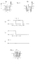
- FIGS. 1a to 1c The basic principle of the present invention can be seen from FIGS. 1a to 1c.
- both boards 1 and 2 are controlled by the control device 7 so that they are in a position in which they can not be gripped by the lifting knives 4, 5.
- the plates 1, 2 are therefore not taken along, i. H. they remain in their subscript.
- the control device 7 is actuated, the lowest position of the roller train 3 is thus actuated, and the associated warp thread 6 is in its lowest adjustable position, the lower compartment UF.
- the control device 7 is controlled on the basis of the jacquard pattern to be formed in such a way that a circuit board 1 of the two circuit boards 1, 2 is in such a position that it is gripped by the associated lifting knife 4 during the upward movement thereof and thus is pulled upwards by the upward movement of this lifting knife 4.
- the other board 2 of the two boards 1, 2 is in the position shown in FIG. 1b and is therefore not taken along by the lifting knife 5 assigned to it when it moves upward and thus remains in its low position.
- three defined specialist positions UF, MF, and OF can thus be achieved with a lifting unit consisting of two circuit boards and two lifting knives as well as a control device.
- FIGS. 2a and 2b A first exemplary embodiment of a control device will be explained below with reference to FIGS. 2a and 2b in connection with the excitation states of the control device shown in FIGS. 3a-3c.
- control device 7 has a single control element for both boards 1 and 2, which is designed in the form of an electromagnet 10.
- This electromagnet 10 can, for example, also be designed as a pivotable electromagnet, as described in DE-A-37 13 832.
- the lifting knives 4, 5 move up and down in relation to one another by a stroke offset which corresponds to a time offset T.
- the control device 7 can be controlled in accordance with this time offset T. The dimensioning of the time offset T is explained below.
- both plates 1, 2 are in such a position that they cannot engage with the associated lifting knife 4 or 5 and thus remain in their respective positions Subscript.
- This first control state thus corresponds to the situation shown in FIG. 1a.
- the associated warp thread 6 is therefore in the sub-compartment UF.
- the electromagnet 10 has been in the energized state ER until the lifting knife 5 has moved past the nose 9 of the associated circuit board 2 during its stroke (upward) movement, the lifting knife 5 due to the excitation ER of the electromagnet 10 could not engage with the board 2 assigned to it.
- a time period t1 (FIG. 3b) that is less than the time offset T, but greater than zero
- the electromagnet 10 is de-energized, which represents the second activation state EN.
- the board 1 is therefore e.g. due to its own spring preload in a position in which it can engage with the lifting knife 4 assigned to it.
- the circuit board 1 is thus pulled into its upper position in this control state by the upward movement of the lifting knife 4.
- the roller train 3 and the associated warp thread 6 are pulled up by half the stroke distance, which is determined by the height difference between the high position H and the low position T of the plate 2.
- the two plates 1, 2 are at the end of the upward movement of both lifting knives 4 and 5 in a position which corresponds to the situation shown in FIG. 1b.
- the associated warp thread 6 is thus in the control of the control device 7 in the middle compartment MF.
- the electromagnet 10 In the event that the electromagnet 10 is in the de-excitation state EN before the lifting knife 5 has moved past the board 2 assigned to it in the course of its lifting movement, the lifting knife 5 engages with the board 2 and is followed by the lifting movement of the lifting knife 5 pulled up. If the electromagnet 10 now remains in this de-energized actuation state EN for a period t2 (FIG. 3c) which is greater than the time offset T, the other circuit board 1 is also in a position at the time when the lifting knife 4 assigned to it passes which engages with the lifting knife 4 and is pulled upwards by its upward movement.
- the two plates 1, 2 are at the end of the upward movements of the two lifting knives 4, 5 in a position that corresponds to the situation shown in FIG. 1c.
- the associated warp thread 6 is thus in the upper compartment OF by lifting the associated roller train 3 when the electromagnet 10 is actuated last.
- the movement of the roller train 3 results from the superposition of the movements of the two lifting knives 4 and 5 offset by the time offset T. 5b).
- the upper compartment OF is formed during a period of time which is essentially between the top dead center of the lifting knife 5 and the top dead center of the lifting knife 4 and thus essentially corresponds to the time offset T.
- the time offset T is thus also to be selected such that when the one board 2 is actuated, the other board 1 can be reliably avoided.
- control device 7 has two separately controllable control elements, each of which is assigned to one of the plates 1, 2.
- the two control elements are advantageously designed in the form of electromagnets 11, 12.
- the two electromagnets 11, 12 are spatially separated by a partition 13 and magnetically shielded to prevent mutual interference between the two electromagnets 11, 12.
- the two electromagnets 11, 12 can each be controlled independently of one another in the de-excited or excited state. It can thus be seen that, depending on the control of the two independent electromagnets 11, 12, pattern-controlled, none or one or both of the plates 1, 2 can be deflected without it requires a time offset T of the up and down movements of the boards 1, 2 and their control.
- both boards 1, 2 Due to the independent control (excitation) of both electromagnets 11, 12, both boards 1, 2 can thus be brought into such a position that they cannot engage with the lifting knives 4 or 5 and therefore during the upward movement of the lifting knives 4, 5 remain in their respective subscripts. As a result of the activation of both electromagnets 11, 12, the associated warp thread 6 is located in the sub-compartment UF.
- one of the plates 1, 2 By actuating (excitation) one of the electromagnets 11, 12, one of the plates 1, 2 can be deflected into such a position that it can engage with the associated lifting knife 4 or 5 and thus by the upward movement of this lifting knife in its high position is pulled, while the other of the two boards 2, 1 remains in its low position due to the de-excitation of the electromagnets 12 and 11 assigned to it. As a result, the associated warp thread 6 is in the middle compartment.
- both boards are e.g. due to their own spring force in such a position that they both engage with their associated lifting knives 4, 5 and are pulled upwards into their respective high positions by their lifting movement.
- the associated warp thread 6 is in the upper compartment OF.
- control can in principle also take place in any other conventional manner - for example by means of needleworks or the like.
- FIG. 6a, b A particularly advantageous embodiment of the invention is shown in Fig. 6a, b.
- the warp thread 6 ′ can be connected at one end of the roller pull cord of a second roller pull 15 instead of directly to the roller pull 3.
- the second end of the roller pull cord of the second roller pull 15 is firmly attached to a frame R.
- the result is a machine with a high compartment mode of operation, ie the control of the boards 1, 2 (reading in E) takes place in the sub-compartment position UF.
- This results in the disadvantage that the path from the read-in position E to the upper compartment position OF is twice as far as the path from the read-in position E to the middle compartment position MF.
- FIG. 6b A particularly elegant solution to this problem is shown in Fig. 6b.
- the frame R to which the fixed end of the roller pull cord of the second roller pull 15 is fastened, can be moved between two height bearings and carries out the up and down movement shown in FIG. 6b.
- Reading E thus takes place in the middle compartment position MF.
- the upper or lower compartment OF or UF can therefore be achieved by a single lifting movement in contrast to the double lifting movement of the embodiment from FIG. 6a.
- the basic idea of the invention can also be applied if the control (reading) takes place in the area of the top dead center position of the lifting knives. It is only necessary (mechanically) to ensure in a manner known per se that the two positions of the sinkers are ensured without the sinker, which is under tensile stress due to the warp thread 6, falling back.
Landscapes
- Engineering & Computer Science (AREA)
- Textile Engineering (AREA)
- Looms (AREA)
Abstract
Description
Die Erfindung betrifft eine Fachbilde-Vorrichtung für eine Jacquardmaschine mit drei definierten Fachstellungen bzw. ein Verfahren zur Steuerung einer Jacquardmaschine mit drei definierten Fachstellungen gemäß den Oberbegriffen des Anspruchs 1 bzw. 13.13. The invention relates to a shedding device for a jacquard machine with three defined positions and a method for controlling a jacquard machine with three defined positions according to the preambles of claims 1 and 13, respectively.
Jacquardmaschinen mit drei definierten Fachstellungen (Unterfach, Mittelfach, Oberfach) werden insbesondere für die Fertigung von Plüschteppichen oder Jacquard-Doppelteppichen benötigt.Jacquard machines with three defined specialist positions (lower, middle, upper) are particularly required for the production of plush carpets or double jacquard carpets.
Fig. 7 zeigt beispielsweise das Bindungsschema eines durchgemusterten Jacquard-Doppelteppichs in der Ausführung als zweischützig gewebter Dreischußteppich. Zur Fertigung solch eines Jacquard-Doppelteppichs muß die Fachbilde-Vorrichtung der Jacquardmaschine drei definierte Fachstellungen für die Kettfäden bereitstellen können, nämlich das Unterfach, das Mittelfach und das Oberfach, in die entsprechende Schußfäden f,g bzw. h eingeschossen werden.FIG. 7 shows, for example, the weave pattern of a patterned double jacquard carpet designed as a two-layer woven three-layer carpet. To manufacture such a double jacquard carpet, the shedding device of the jacquard machine must be able to provide three defined shed positions for the warp threads, namely the lower shed, the middle shed and the upper shed, into which corresponding weft threads f, g and h are shot.
Im Falle des dargestellten Doppelteppichs werden wie dargestellt zwei Grundgewebe a, b mit einem der doppelten Florhöhe eines Teppichs entsprechenden Abstand übereinandergewebt, verbunden durch Polkettfäden i. Die Schußschlaufen der Polkettfäden i werden zwischen den beiden Grundgeweben a,b von dem Messer j durchgeschnitten und die beiden Grundgewebe a,b somit getrennt. Es ist ersichtlich, daß die drei definierten Fachstellungen jeweils synchron für die beiden Grundgewebe a,b angesteuert werden.In the case of the double carpet shown, two base fabrics a, b are woven as shown, with a distance corresponding to twice the pile height of a carpet, connected by pile warp threads i. The weft loops of the pile warp threads i are cut between the two base fabrics a, b by the knife j and the two base fabrics a, b are thus separated. It can be seen that the three defined specialist positions are controlled synchronously for the two base fabrics a, b.
Klassisch ist beispielsweise eine Ansteuerung einer Jacquardmaschine, bei der zwei Platinen über einen gemeinsamen Rollenzug am unteren Ende verbunden sind, wobei die Platinen je nach Ansteuerung meist mit zwei ständig gegenläufigen bewegten Hubmessern koppelbar sind, wodurch dem Rollenzug und dem damit verbundenen Kettfaden eine gesteuerte Hubbewegung erteilt wird. Bei solch einer Jacquardmaschine mit bewegbaren Hubmessern ist in einer Stellung der Hubmesser jeder Platine die Möglichkeit zu geben, den Eingriff zwischen dieser Platine und dem zugehörigen Hubmesser mustergesteuert zu lösen oder nicht und auch wiederherzustellen, um ein gewünschtes Jacquardmuster erzielen zu können. Herkömmlich sind Nadelwerke, die in einer Stellung, bei der Platine und zugehöriges Hubmesser außer Eingriff sind, die Platine aus dem Bewegungsweg der Hubmesser herausbewegen, so daß bei der nächsten Bewegung des Hubmessers dieses an der so angesteuerten Platine vorbeibewegt wird und diese nicht mitnimmt. Dieses sog.A classic example is a control of a jacquard machine, in which two sinkers are connected via a common roller train at the lower end, whereby the sinkers can, depending on the control, usually be coupled with two constantly opposing moving lifting knives, which gives the roller train and the associated warp thread a controlled lifting movement becomes. In such a jacquard machine with movable lifting knives, in one position of the lifting knives each board has the possibility to release or not to engage the engagement between this board and the associated lifting knife in a pattern-controlled manner and also to restore it in order to be able to achieve a desired jacquard pattern. Conventionally, needle mechanisms, which are in a position in which the circuit board and associated lifting knife are disengaged, move the circuit board out of the movement path of the lifting knife, so that the next time the lifting knife is moved, it is moved past the circuit board controlled in this way and does not take it along. This so-called
Einlesen kann nicht nur auf mechanischem Wege, sondern, wie bei modernen Maschinen üblich, auch auf elektromagnetischem Wege erfolgen, und zwar dadurch, daß ein Elektromagnet in einem seiner Erregungszustände dazu dient, die Platine auszulenken und in dem ausgelenkten Zustand (angesteuertem Zustand) zu halten, während in dem anderen Erregungszustand keine Auslenkung erfolgt und das Hubmesser die Platine mitnehmen kann. Wesentlich ist dabei nur, dem Rollenzug eine Bewegung zu erteilen und ferner die Platinen dabei relativ zu einer Ansteuervorrichtung so zu bewegen, daß die mustergemäße Ansteuerung möglich ist. Mit bei elektronischen Rollenzugmaschinen klassischen Steuervorrichtungen sind jedoch mit einer Hubeinheit bestehend aus zwei Hubmessern und zwei Platinen nur zwei definierte Fachstellungen möglich.Reading can take place not only mechanically, but, as is customary in modern machines, also electromagnetically, namely in that an electromagnet in one of its excitation states serves to deflect the circuit board and to keep it in the deflected state (activated state) , while in the other state of excitation there is no deflection and the lifting knife can take the board with it. It is only important to give the roller train a movement and also to move the boards relative to a control device in such a way that the control according to the model is possible. With classic control devices for electronic roller tractors, however, only two defined specialist positions are possible with a lifting unit consisting of two lifting knives and two boards.
Um eine Fachbilde-Vorrichtung mit drei definierten Fachstellungen zu schaffen, werden üblicherweise zwei Hubeinheiten über eine zusätzliche Umlenkrolle miteinander verbunden, d. h., daß somit zur Erreichung von drei definierten Fachstellungen vier Platinen und vier Hubmesser pro Kettfaden benötigt werden. Es ist ersichtlich, daß dadurch der Raum- und Energiebedarf, die Wärmeentwicklung sowie der mechanische Aufwand erheblich steigen oder die effektive Zahl von Hebevorrichtungen durch die Verbindung von zwei Hubeinheiten halbiert wird. Die genannten Nachteile werden bei der Verwendung der bekannten Fachbilde-Vorrichtung zur Herstellung eines Jacqard-Doppelteppiches noch bedeutender, da wie oben erklärt zur Herstellung eines Doppelteppiches je drei Fachstellungen für zwei Grundgewebe benötigt werden, was für sich schon eine aufwendige Mechanik zur Folge hat. Schließlich ist bei solch hohem mechanischen und steuertechnischen Aufwand auch mit hoher Fehlerquote und hoher Ausfallquote zu rechnen.In order to create a shed forming device with three defined shed positions, two lifting units are usually connected to one another via an additional deflection roller, i. This means that four plates and four lifting knives per warp thread are required to achieve three defined positions. It can be seen that the space and energy requirements, the heat development and the mechanical outlay increase considerably, or the effective number of lifting devices is halved by the connection of two lifting units. The disadvantages mentioned become even more significant when using the known shedding device for the production of a Jacqard double carpet, since, as explained above, three specialist positions are required for two basic fabrics to produce a double carpet, which in itself has a complex mechanism. After all, with such a high mechanical and control expenditure, a high error rate and high failure rate can also be expected.
Ausgehend hiervon ist es Aufgabe der vorliegenden Erfindung, eine Fachbilde-Vorrichtung und ein Verfahren zur Steuerung einer Fachbilde-Vorrichtung der oben genannten Art so weiterzubilden, daß bei einfachem mechanischen Aufbau unter Reduzierung der Zahl der Platinen pro Hebevorrichtung ein sichererer und wirtschaftlicherer Betrieb möglich ist.Proceeding from this, it is an object of the present invention to develop a shedding device and a method for controlling a shedding device of the above-mentioned type in such a way that, with a simple mechanical structure and a reduction in the number of boards per lifting device, a safer and more economical operation is possible.
Die Aufgabe wird durch die kennzeichnenden Merkmale der Ansprüche 1 bzw. 13 gelöst. Die Erfindung wird durch die Merkmale der Unteransprüche weitergebildet.The object is solved by the characterizing features of claims 1 and 13, respectively. The invention is further developed by the features of the subclaims.
Die Erfindung geht dabei von der Erkenntnis aus, daß durch geringe Änderungen aus einer Doppelhub-Maschine mit zwei Fachstellungen eine Einhub-Maschine mit drei Stellungen geschaffen werden kann. Unter Inkaufnahme einer aufwendigeren Steuerung bei einer Fachbilde-Vorrichtung können somit auch drei definierte Fachstellungen erreicht werden, wenn nur zwei Platinen pro Hebevorrichtung verwendet werden und somit der mechanische Aufwand erheblich verringert wird. Entscheidend dafür ist, daß die Steuervorrichtung so ausgebildet ist, daß sie mustergesteuert wahlweise keine, eine oder beide Platinen auslenkt. Bei den bekannten Vorrichtungen sind dagegen entweder keine oder beiden Platinen auslenkbar. Der mechanische Aufwand ist somit in unerwarteter Weise bei der Vorrichtung bzw. dem Verfahren in etwa genauso groß wie für eine Fachbilde-Vorrichtung für zwei definierte Fachstellungen bzw. eine Verfahren zur deren Steuerung. Die zu erwartenden Probleme bei der dadurch komplizierteren Ansteuerung der Fachbilde-Vorrichtung werden erfindungsgemäß überraschend einfach gelöst.The invention is based on the knowledge that a single-stroke machine with three positions can be created from small changes from a double-stroke machine with two specialist positions. By accepting a more complex control in a shedding device, three defined shots can also be achieved, if only two boards are used per lifting device and thus the mechanical effort is significantly reduced. The decisive factor here is that the control device is designed in such a way that it pattern-selectively deflects none, one or both boards. In the known devices, however, either none or both boards can be deflected. The mechanical effort in the device or the method is thus unexpectedly roughly the same as for a shedding device for two defined positions or a method for controlling it. According to the invention, the problems to be expected in the thereby more complicated control of the shedding device are surprisingly simply solved.
Die Auslenkung von wahlweise einer, keiner oder beiden Platinen wird in einem Ausführungsbeispiel durch einen Quasi-Gleichlauf mit geringem Zeitversatz der Auf- und Abbewegung der beiden Platinen zusammen mit einer dem Zeitversatz entsprechenden Ansteuerung einer ein Steuerelement enthaltenden Steuervorrichtung erreicht.In one exemplary embodiment, the deflection of one, none or both boards is achieved by a quasi-synchronization with a slight time offset of the up and down movement of the two boards together with a control of a control device containing a control element corresponding to the time offset.
In einem weiteren Ausführungsbeispiel erfolgt die unabhängigen Auslenkung der Platinen dadurch, daß die Steuervorrichtung getrennt ansteuerbare, je einer der Platinen zugeordnete Steuerelemente aufweist.In a further exemplary embodiment, the independent deflection of the circuit boards takes place in that the control device has separately controllable control elements, each associated with one of the circuit boards.
Die Erfindung wird anhand der in der Zeichnung dargestellten Ausführungsbeispiele erläutert. Es zeigen:
- Fig. 1a-1c
- schematisch eine grundsätzliche Ausführungsform einer erfindungsgemäßen Fachbilde-Vorrichtung,
- Fig. 2a, 2b
- detailliert eine Steuervorrichtung einer erfindungsgemäßen Fachbilde-Vorrichtung gemäß einem ersten Ausführungsbeispiel,
- Fig. 3a-3c
- schematisch die Erregungszustände einer Ansteuervorrichtung bei dem ersten Ausführungsbeispiel,
- Fig. 4
- detailliert eine weitere Steuervorrichtung einer erfindungsgemäßen Fachbilde-Vorrichtung gemäß einem weiteren Ausführungsbeispiel,
- Fig. 5
- ein Zeitverlaufsdiagramm der Bewegung der Kettfäden bei einer Fachbilde-Vorrichtung gemäß dem ersten oder dem zweiten Ausführungsbeispiel,
- Fig. 6a,b
- Zeitverlaufsdiagramme der Bewegung der Kettfäden und Fachbildevorrichtungen gemäß besonders vorteilhaften Ausführungsformen der Erfindung, und
- Fig. 7
- ein Bindungsschema eines Jacquard-Doppelteppichs.
- 1a-1c
- schematically a basic embodiment of a shedding device according to the invention,
- 2a, 2b
- a control device of a shedding device according to the invention according to a first embodiment in detail,
- 3a-3c
- schematically the excitation states of a control device in the first embodiment,
- Fig. 4
- in detail another control device of a shedding device according to the invention according to a further embodiment,
- Fig. 5
- FIG. 2 shows a time course diagram of the movement of the warp threads in a shedding device according to the first or the second exemplary embodiment,
- 6a, b
- Timing diagrams of the movement of the warp threads and shedding devices according to particularly advantageous embodiments of the invention, and
- Fig. 7
- a weave scheme of a double jacquard rug.
Gemäß Fig. 1a sind zwei Platinen 1 und 2 über einen gemeinsamen Rollenzug 3 am unteren Ende miteinander verbunden. Jeder Platine 1, 2 ist ein Hubmesser 4 bzw. 5 zugeordnet, die in üblicher Weise zwischen einer Hochstellung H und einer Tiefstellung T bewegbar sind. Mit dem Rollenzug 3 ist in üblicher Weise ein Kettfaden 6 verbunden, dem durch die Auf- und Abbewegung des Rollenzugs 3 eine gesteuerte Hubbewegung erteilt wird. Die Platinen 1, 2 sind in Führungen zur geradlinigen Bewegung zwischen Hochstellungen H und Tiefstellungen T geführt. Den beiden durch den Rollenzug 3 miteinander verbundenen Platinen 1 und 2 eine Steuervorrichtung 7 zugeordnet, die vorteilhaft wie schematisch dargestellt zwischen den Bewegungswegen der beiden Platinen 1,2 angeordnet ist. Die Steuervorrrichtung 7 kann jedoch auch in jeder anderen Lage bezüglich der beiden Platinen 1,2 vorgesehen sein, wesentlich ist, daß die mustergemäße Ansteuerung erfolgen kann.1a, two
Jede Platine 1, 2 weist ein Nase 8 bzw. 9 auf, die von der jeweiligen Platine 1, 2 wegragt. Wird die Steuervorrichtung 7 angesteuert, so wird die entsprechende Platine von der Steuervorrichtung 7 ausgelenkt und das Hubmesser 4 bzw. 5 geht bei seiner Hubbewegung vorbei, ohne die Nase 8 der Platine 1 zu ergreifen und somit die Platine 1 mitnehmen zu können. Die Platine 1 verbleibt also in ihrer Tiefstellung T. Ist die Steuervorichtung 7 dagegen in dem anderen Ansteuerzustand, also "nicht angesteuert", so geht die zugehörige Platine 1 bzw. 2 z. B. aufgrund einer Federkraft wieder in diejenige Lage zurück, in der das zugehörige Hubmesser 4 bzw. 5 sie über die Nase 8,9 ergreifen kann, bzw. lenkt die Platine nicht aus.Each
Aus Fig. 1a bis 1c ist das Grundprinzip der vorliegenden Erfindung ersichtlich. In Fig. 1a sind beide Platinen 1 und 2 von der Steuervorrichtung 7 so angesteuert, daß sie sich in einer Position befinden, in der sie von den Hubmesern 4,5 nicht ergriffen werden können. Bei der Aufwärtsbewegung der zugehörigen Hubmesser 4 bzw. 5 werden die Platinen 1,2 daher nicht mitgenommen, d. h. sie verbleiben in ihrer Tiefstellung. Bei dieser Ansteuerung der Steuervorrichtung 7 wird somit die tiefste Stellung des Rollenzugs 3 angesteuert, und der zugehörige Kettfaden 6 befindet sich in seiner untersten einstellbaren Stellung, dem Unterfach UF.The basic principle of the present invention can be seen from FIGS. 1a to 1c. In Fig. 1a, both
In dem in Fig. 1b dargestellten Zustand ist die Steuervorrichtung 7 so aufgrund des zu bildenden Jacqardmusters angesteuert, daß sich eine Platine 1 der beiden Platinen 1, 2 in einer solche Lage befindet, daß sie bei der Aufwärtsbewegung des zugeordneten Hubmessers 4 von diesem ergriffen wird und somit durch die Aufwärtsbewegung dieses Hubmessers 4 nach oben gezogen wird. Bei dieser Ansteuerung der Steuervorrichtung 7 ist indessen die andere Platine 2 der beiden Platinen 1, 2 in der in Fig.1b gezeigten Position und wird daher von dem ihr zugeordneten Hubmesser 5 bei dessen Aufwärtsbewegung nicht mitgenommen und verbleibt somit in ihrer Tiefstellung.In the state shown in FIG. 1b, the
Als Ergebnis wird der Rollenzug 3 und somit der zugehörige Kettfaden 6 in eine gegenüber der Stellung von Fig. 2a etwas angehobenen Stellung gezogen, das sogenannte Mittelfach MF.As a result, the
In Fig. 1c ist die Steuervorrichtung 7 dagegen so angesteuert, daß beide Platinen 1 und 2 durch die Steuervorichtung 7 jeweils in eine Position gebracht wurden, bei der sie bei der Aufwärtsbewegung der beiden Hubmesser 4 bzw. 5 jeweils in ihre obere Stellung mitgenommen sind. Als Ergebnis ist der Rollenzug 3 und somit der zugehörige Kettfaden 6 in eine noch weiter angehobene Stellung gebracht, die noch weiter oberhalb der in Fig. 1b dargestellten Stelllung liegt und somit das sogenannte Oberfach OF darstellt.In Fig. 1c, the
Wie in Fig. 1a bis 1c gezeigt, lassen sich somit mit einer Hubeinheit bestehend aus zwei Platinen und zwei Hubmessern sowie einer Steuervorrichtung drei definierte Fachstellungen UF, MF, und OF erreichen.As shown in FIGS. 1a to 1c, three defined specialist positions UF, MF, and OF can thus be achieved with a lifting unit consisting of two circuit boards and two lifting knives as well as a control device.
Im folgenden soll ein erstes Ausführungsbeispiel einer Steuervorrichtung bezugnehmend auf Fig.2a und 2b im Zusammenhang mit den in Fig.3a-3c dargestellten Erregungszuständen der Steuervorrichtung erläutert werden.A first exemplary embodiment of a control device will be explained below with reference to FIGS. 2a and 2b in connection with the excitation states of the control device shown in FIGS. 3a-3c.
In Fig.2a weist die Steuervorrichtung 7 ein einziges Steuerelement für beide Platinen 1 und 2 auf, das in einer Form eines Elektromagneten 10 ausgeführt ist. Dieser Elektromagnet 10 kann beispielsweise auch als ein schwenkbarer Elektromagnet ausgeführt sein, wie er in der DE-A-37 13 832 beschrieben ist.In Figure 2a, the
Wie aus der Fig.2a und b ersichtlich bewegen sich die Hubmesser 4,5 um einen Hubversatz, der einem Zeitversatz T entspricht, zueinander versetzt auf und ab. Die Steuervorrichtung 7 ist entsprechend diesem Zeitversatz T ansteuerbar. Die Bemessung des Zeitversatzes T wird weiter unten erläutert.As can be seen from FIGS. 2a and b, the lifting
Wenn der Elektromagnet 10 während Zeitspannen t1 (Fig.3a) in dem Erregungszustand ER (angesteuert) ist, in der sowohl das Hubmesser 5 an der Nase 9 der ihm zugeordneten Platine 2, als auch das Hubmesser 4 an der Nase 8 der ihm zugeordneten Platine 1 im Verlauf ihrer um den Zeitversatz T versetzten Aufwärtsbewegung vorbeiziehen, befinden sich beide Platinen 1,2 in einer solchen Position, daß sie nicht mit dem zugehörigen Hubmesser 4 bzw. 5 Eingriff treten können und verbleiben somit in ihrer jeweiligen Tiefstellung. Dieser erste Ansteuerzustand entspricht somit der in Fig. 1a dargestellten Situation. Der zugehörige Kettfaden 6 befindet sich also im Unterfach UF.If the
In Fig.2b ist der Elektromagnet 10 so lange im Erregungszustand ER (gewesen), bis das Hubmesser 5 an der Nase 9 der zugehörigen Platine 2 im Verlauf seiner Hub(Aufwärts)Bewegung vorbeigezogen ist, wobei das Hubmesser 5 aufgrund der Erregung ER des Elektromagneten 10 nicht mit der ihm zugeordneten Platine 2 in Eingriff treten konnte. Nach einer Zeitspanne t1 (Fig.3b), die kleiner als der Zeitversatz T, jedoch größer Null ist, wird der Elektromagnet 10 entregt, was den zweiten Ansteuerzustand EN darstellt. Die Platine 1 ist daher z.B. auf Grund einer ihr eigenen Federvorspannung in einer Position, in der sie mit dem ihr zugeordneten Hubmesser 4 in Eingriff treten kann. Die Platine 1 wird somit in diesem Ansteuerzustand durch die Aufwärtsbewegung des Hubmessers 4 in ihre obere Stellung gezogen. Dadurch wird der Rollenzug 3 und der zugehörige Kettfaden 6 um die Hälfte der Hubstrecke nach oben gezogen, die durch die Höhendifferenz zwischen der Hochstellung H und der Tiefstellung T der Platine 2 festgelegt ist.In FIG. 2b, the
Als Ergebnis befinden sich die beiden Platinen 1,2 am Ende der Aufwärtsbewegung beider Hubmesser 4 und 5 in einer Position, die der in Fig.1b dargestellten Situation entspricht. Der zugehörige Kettfaden 6 befindet sich also bei dieser Ansteuerung der Steuervorrichtung 7 im Mittelfach MF.As a result, the two
Für den Fall, daß der Elektromagnet 10 in dem Entregungszustand EN ist, bevor das Hubmesser 5 im Verlauf seiner Hubbewegung an der ihm zugeordneten Platine 2 vorbeigezogen ist, tritt das Hubmesser 5 mit der Platine 2 in Eingriff und wird durch die Hubbewegung des Hubmessers 5 nach oben gezogen. Wenn nun der Elektromagnet 10 während einer Zeitspanne t2 (Fig.3c), die größer als der Zeitversatz T ist, in diesem entregten Ansteuerzustand EN verbleibt, ist die andere Platine 1 zum Zeitpunkt des Vorbeigangs des ihr zugeordneten Hubmessers 4 ebenfalls in einer Position, in der sie mit dem Hubmesser 4 in Eingriff tritt und durch dessen Aufwärtsbewegung nach oben gezogen wird.In the event that the
Als Ergebnis befinden sich die beiden Platinen 1,2 am Ende der Aufwärtsbewegungen der beiden Hubmesser 4,5 in einer Position, die der in Fig.1c dargestellten Situation entspricht. Der zugehörige Kettfaden 6 befindet sich also durch das Anheben des zugehörigen Rollenzugs 3 bei der zuletzt geschilderten Ansteuerung des Elektromagneten 10 im Oberfach OF.As a result, the two
Wie detailliert in Fig. 5 dargestellt ist, resultiert die Bewegung des Rollenzugs 3 (s.a. Fig.1) und damit des zugeordneten Kettfadens 6 (Fig. 5a) aus der Überlagerung der um den Zeitversatz T versetzten Bewegungen der beiden Hubmesser 4 und 5 (Fig. 5b). Wie aus Fig. 5a und 5b ersichtlich ist, wird das Oberfach OF während einer Zeitdauer gebildet, die im wesentlichen zwischen dem Erreichen des oberen Totpunkts des Hubmessers 5 und dem Erreichen des oberen Totpunkts des Hubmessers 4 liegt und somit im wesentlichen dem Zeitversatz T entspricht. Wie indessen in Fig.5b ebenfalls durch den schraffierten Bereich gezeigt ist, weicht der ideale Zustand d. h. Hub-Maximalwert, bei dem kein Zeitversatz auftritt (der aber nur mit getrennter Ansteuerung der Platinen bezüglich der beiden Hubmesser 4 und 5 möglich ist) vom real erreichbaren Hubwert des Kettfadens 6 deutlich ab, und zwar umsomehr je größer der Zeitversatz T ist (im Extremfall können sich diese Bewegungen sogar gegenseitig auslöschen). Somit ist ersichtlich, daß hinsichtlich des Zeitversatzes T ein Kompromiß zwischen der zeitlichen Dauer des Offenfachs OF und einem ausreichenden Niveauunterschied zwischen den jeweiligen Fachstellungen UF,MF,OF gefunden werden muß.As shown in detail in FIG. 5, the movement of the roller train 3 (see also FIG. 1) and thus of the associated warp thread 6 (FIG. 5a) results from the superposition of the movements of the two lifting
Bei der Wahl des Zeitversatzes T ist weiterhin zu bedenken, daß, wenn eine Platinen-Stellung erreicht werden soll, die der Unterfachstellung UF oder der Mittelfachstellung MF entspricht, das Hubmesser 5 zum Zeitpunkt der Entregung des Elektromagneten 10 zur Auslenkung der Platine 1 bereits an der Nase der nunmehr ebenfalls ausgelenkten Platine 2 vorbeigezogen ist und die Platine 2 somit sicher außer Eingriff mit dem Hubmesser 5 verbleibt.When choosing the time offset T it should also be borne in mind that if a circuit board position is to be achieved which corresponds to the sub-compartment position UF or the middle compartment position MF, the lifting
Der Zeitversatz T ist somit auch so zu wählen, daß bei einer Ansteuerung der einen Platine 2 eine Ansteuerung der anderen Platine 1 sicher vermieden werden kann.The time offset T is thus also to be selected such that when the one
In dem in Fig.4 dargestellten Ausführungsbeispiel eines Details einer erfindungsgemäßen Fachbilde-Vorichtung weist die Steuervorrichtung 7 zwei getrennt ansteuerbare Steuerelemente auf, die je einer der Platinen 1,2 zugeordnet sind. In dem dargestellten Ausführungsbeispiel sind die beiden Steuerelemente vorteilhaft in Form von Elektromagneten 11,12 ausgeführt.In the exemplary embodiment shown in FIG. 4 of a detail of a shedding device according to the invention, the
Die beiden Elektromagneten 11,12 sind durch eine Trennwand 13 räumlich getrennt und magnetisch abgeschirmt, um eine gegenseitige Beeinflussung der beiden Elektromagnete 11,12 zu vehindern. Die beiden Elektromagnete 11,12 können unabhängig voneinander jeweils in den entregten bzw. erregten Zustand angesteuert werden. Somit ist es ersichtlich, daß je nach Ansteuerung der beiden unabhängigen Elektromagneten 11,12 mustergesteuert keine, eine oder beide Platinen 1,2 ausgelenkt werden können, ohne daß es dazu eines Zeitversatzes T der Auf- und Abbewegungen der Platinen 1,2 und deren Ansteuerung bedarf.The two
Durch die unabhängige Ansteuerung (Erregung) beider Elektromagneten 11,12 können somit beide Platinen 1,2 in eine solche Position gebracht werden, daß sie mit den Hubmessern 4 bzw.5 nicht in Eingriff treten können und daher bei der Aufwärtsbewegung der Hubmesser 4,5 in ihrer jeweiligen Tiefstellung verbleiben. Als Ergebnis der Ansteuerung beider Elektromagnete 11,12 befindet sich der zugehörige Kettfaden 6 im Unterfach UF.Due to the independent control (excitation) of both
Durch Ansteuerung (Erregung) eines der Elektromagneten 11,12 kann eine der Platinen 1,2 in solch eine Position ausgelenkt werden, daß sie mit den ihr zugeordneten Hubmesser 4 bzw. 5 in Eingriff treten kann und somit durch die Aufwärtsbewegung dieses Hubmessers nach oben in ihre Hochstellung gezogen wird, während die andere der beiden Platinen 2,1 durch die Entregung des ihr zugeordneten Elektromagneten 12 bzw. 11 in ihrer Tiefstellung verbleibt. Als Ergebnis befindet sich der zugehörige Kettfaden 6 im Mittelfach.By actuating (excitation) one of the
Wenn die beiden Elektromagneten 11,12 so angesteuert sind, daß sie beide entregt sind, befinden sich beide Platinen z.B. auf Grund einer ihnen eigenen Federkraft in einer solchen Position, daß sie beide mit ihren zugeordneten Hubmessern 4,5 in Eingriff treten und durch deren Hubbewegung nach oben in ihre jeweilige Hochstellung gezogen werden. Als Ergebnis befindet sich der zugehörige Kettfaden 6 im Oberfach OF.If the two
Bei der Ansteuerung mit Hilfe von Elektromagneten kann ein an sich bekanntes Anbieten erfolgen, bei dem die jeweilige Platine mechanisch in geringem Abstand zu dem oder in Anlage an den Elektromagneten gebracht wird und mechanisch wieder in die nicht ausgelenkte Lage gebracht wird, wenn ihre Ansteuerung durch Erregung des Elektromagneten erfolgt, wobei dann das zugehörige Hubmesser die Platine (wieder) mitnimmt (vgl. ebenfalls DE-A-37 13 832).When actuating with the aid of electromagnets, a known offer can be made, in which the respective circuit board is mechanically placed at a short distance from or in contact with the electromagnet and is mechanically brought back into the undeflected position when actuated by excitation of the electromagnet, the associated lifting knife then (again) taking the board with it (cf. also DE-A-37 13 832).
Schließlich kann die Ansteuerung grundsätzlich auch in jeder anderen herkömmlichen Weise erfolgen- etwa mittels Nadelwerken oder dgl.Finally, the control can in principle also take place in any other conventional manner - for example by means of needleworks or the like.
Eine besonders vorteilhafte Ausführungsform der Erfindung ist in Fig. 6a,b dargestellt.A particularly advantageous embodiment of the invention is shown in Fig. 6a, b.
Wie in Fig. 6a dargestellt ist, kann der Kettfaden 6' an einem Ende der Rollenzugschnur eines zweiten Rollenzugs 15 anstatt direkt mit dem Rollenzug 3 verbunden sein. Das zweite Ende der Rollenzugschnur des zweiten Rollenzugs 15 ist dabei fest an einem Rahmen R befestigt. Es ergibt sich somit eine Maschine mit Hochfach-Arbeitsweise, d.h. das Ansteuern der Platinen 1,2 (Einlesen E) erfolgt in der Unterfach-Stellung UF. Bei jedem Schuß wird wenn gewünscht das Mittel- und Oberfach MF,OF angefahren (angesteuert). Danach wird wieder in die Einlese-Stellung (=Unterfach UF) zurückgekehrt. Daraus ergibt sich der Nachteil, daß der Weg von der Einlese-Stellung E zu der Oberfach-Stellung OF doppelt so weit ist wie der Weg von der Einlese-Stellung E zu der Mittelfach-Stellung MF.As shown in FIG. 6 a, the
Eine besonders elegante Lösung dieses Problems ist in Fig.6b dargestellt. Bei dieser Ausführungsform ist der Rahmen R, an dem das feste Ende der Rollenzugschnur des zweiten Rollenzugs 15 befestigt ist, zwischen zwei Höhenlager bewegbar und führt die in Fig.6b dargestellte Auf- und Abbewegung aus. Das Einlesen E erfolgt somit in der Mittelfach-Stellung MF. Das Ober- bzw. Unterfach OF bzw. UF sind daher durch eine einfach Hubbewegung im Gegensatz zu der doppelten Hubbewegung der Ausführungsform von Fig. 6a zu erreichen. Die Bewegung des Kettfadens 6' wird somit geringer.A particularly elegant solution to this problem is shown in Fig. 6b. In this embodiment, the frame R, to which the fixed end of the roller pull cord of the second roller pull 15 is fastened, can be moved between two height bearings and carries out the up and down movement shown in FIG. 6b. Reading E thus takes place in the middle compartment position MF. The upper or lower compartment OF or UF can therefore be achieved by a single lifting movement in contrast to the double lifting movement of the embodiment from FIG. 6a. The movement of the warp thread 6 'is therefore less.
Für die anhand Fig. 3a erläuterte Anregung des Elektromagneten 10 für das Unterfach UF ist es nicht zwingend erforderlich, zwei Erregungsimpulse, die um den Zeitversatz T versetzt sind, vorzusehen. Vielmehr reicht es aus, wenn, wie durch eine Strichpunktlinie in Fig. 3a dargestellt, der Elektromagnet 10 während der Zeitspanne im Erregungszustand ER ist, in der sowohl das Hubmesser 5 als auch das Hubmesser 4 an den jeweiligen Platinen 1 bzw. 2 vorbeiziehen. In gleicher Weise ist es nicht zwingend erforderlich, für das Mittelfach MF (vgl. Fig. 3b und Fig. 4) ausschließlich die Platine 1, die dem Hubmesser 4 zugeordnet ist, anzusteuern. Vielmehr kann alternativ dazu selbstverständlich auch die Platine 2, die dem Hubmesser 5 zugeordnet ist, angesteuert werden (nicht im einzelnen dargestellt).For the excitation of the
Grundsätzlich kann die Grundidee der Erfindung auch angewendet werden, wenn die Ansteuerung (Einlesen) im Bereich der oberen Totpunktlage der Hubmesser erfolgt. Es ist lediglich (mechanisch) in an sich bekannter Weise sicherzustellen, daß die beiden Positionen der Platinen gewährleistet sind, ohne daß die unter Zugspannung durch den Kettfaden 6 stehende Platine nach unten zurückfällt.In principle, the basic idea of the invention can also be applied if the control (reading) takes place in the area of the top dead center position of the lifting knives. It is only necessary (mechanically) to ensure in a manner known per se that the two positions of the sinkers are ensured without the sinker, which is under tensile stress due to the
Claims (28)
dadurch gekennzeichnet,
daß zur Erreichung der drei Fachstellungen (UF,MF,OF) die Steuervorrichtung (7) so ausgebildet ist, daß sie mustergesteuert wahlweise keine, eine oder beide Platinen (1,2) auslenkt.Shed forming device for a jacquard machine with three defined shed positions (UF, MF, OF), in which two plates (1, 2) connected at one end via a common roller train (3) by means of a lifting knife arrangement (4, 5) each between an upper and a lower position are movable, and a control device (7) which can be controlled on the basis of the pattern to be formed is assigned to the movement paths of the two boards (1, 2) in such a way that one of the boards (1 , 2) can be deflected into a position in which no movement of this circuit board (1, 2) is possible, while the respective circuit board (1, 2) can be moved in the position corresponding to a further control state (EN),
characterized by
that in order to achieve the three specialist positions (UF, MF, OF), the control device (7) is designed in such a way that, depending on the pattern, it deflects none, one or both boards (1, 2).
dadurch gekennzeichnet,
daß die Steuervorrichtung (7) zwischen den Bewegungswegen der Platinen (1,2) vorgesehen ist.Device according to claim 1,
characterized by
that the control device (7) is provided between the paths of movement of the boards (1, 2).
dadurch gekennzeichnet,
daß die Auf- und Abbewegungen der beiden Platinen (1,2) um einen kleinen, jedoch endlichen Wert (T) zueinander zeitversetzt sind.Device according to claim 1 or 2,
characterized by
that the up and down movements of the two plates (1, 2) are offset in time by a small but finite value (T).
dadurch gekennzeichnet,
daß die Steuervorrichtung (7) entsprechend dem Zeitversatz (T)ansteuerbar ist.Device according to claim 3,
characterized by
that the control device (7) can be controlled according to the time offset (T).
dadurch gekennzeichnet,
daß die Steuervorrichtung (7) ein einziges Steuerelement (10) für beide Platinen (1,2) aufweist und dieses für je eine der Platinen (1,2) zeitlich versetzt ansteuerbar ist.Device according to one of the preceding claims,
characterized by
that the control device (7) has a single control element (10) for both boards (1, 2) and this can be actuated at different times for each of the boards (1, 2).
dadurch gekennzeichnet,
daß der Zeitversatz (T) so klein wie möglich, jedoch größer Null ist.Device according to one of claims 3-5,
characterized by
that the time offset (T) is as small as possible, but greater than zero.
dadurch gekennzeichnet,
daß der Zeitversatz (T) so bestimmt ist, daß bei der Ansteuerung einer der Platinen (1,2) eine Ansteuerung der jeweils anderen Platine (1,2) sicher vermieden ist.Apparatus according to claim 6,
characterized by
that the time offset (T) is determined so that when one of the boards (1, 2) is actuated, actuation of the other board (1, 2) is reliably avoided.
dadurch gekennzeichnet,
daß die Steuervorrichtung (7) getrennt ansteuerbare, je einer der Platinen zugeordnete Steuerelemente (11,12) aufweist.Device according to one of the preceding claims,
characterized by
that the control device (7) has separately controllable control elements (11, 12) assigned to each of the boards.
dadurch gekennzeichnet,
daß die Steuervorrichtung (7) die Platinen (1,2) auf elektromagnetischer Grundlage auslenkt.Device according to one of the preceding claims,
characterized by
that the control device (7) deflects the boards (1, 2) on an electromagnetic basis.
dadurch gekennzeichnet,
daß die Steuervorrichtung (7) die Platinen (1,2) mechanisch auslenkt.Device according to one of claims 1 to 8,
characterized by
that the control device (7) mechanically deflects the boards (1, 2).
dadurch gekennzeichnet,
daß sie in einer Doppelteppich-Webmaschine vorgesehen ist.Device according to one of the preceding claims,
characterized by
that it is provided in a double carpet weaving machine.
dadurch gekennzeichnet,
daß sie in einer Webmaschine für Plüschteppiche vorgesehen ist.Device according to one of claims 1 to 10,
characterized by
that it is provided in a weaving machine for plush carpets.
dadurch gekennzeichnet,
daß ein zweiter Rollenzug (15) mit dem ersten Rollenzug (3) verbunden ist, wobei ein Kettfaden (6') der Rollenzugschnur des zweiten Rollenzugs (15) zugeordnet ist.Device according to one of the preceding claims,
characterized by
that a second roller train (15) is connected to the first roller train (3), a warp thread (6 ') being associated with the roller train cord of the second roller train (15).
dadurch gekennzeichnet,
daß ein Ende der Rollenzugschnur des zweiten Rollenzugs (15) fest an einem Rahmen (R) angebracht ist, wobei der Rahmen (R) entsprechend der Auf- und Abbewegungen der beiden Platinen (1,2) bewegbar ist.Device according to claim 13,
characterized by
that one end of the roller pull cord of the second roller pull (15) is fixedly attached to a frame (R), the frame (R) being movable in accordance with the up and down movements of the two plates (1, 2).
dadurch gekennzeichnet,
daß zur Erreichung der drei Fachstellungen (UF,MF,OF) die Steuervorrichtung (7) mustergesteuert wahlweise keine, eine oder beide Platinen (1,2) auslenkt.Method for controlling a jacquard machine with three defined positions (UF, MF, OF), in which two boards (1, 2) connected at one end via a common roller train (3) by means of a lifting knife arrangement (4, 5) each between one and a lower position can be moved, and a control device (7) driven on the basis of the pattern to be formed in a first control state (ER) deflects one of the boards into a position in which no movement of this board is possible while in one position, the respective circuit board can be moved,
characterized by
that to achieve the three specialist positions (UF, MF, OF) the control device (7) pattern-controlled optionally deflects none, one or both boards (1, 2).
dadurch gekennzeichnet,
daß sich die beiden Platinen um einen kleinen, jedoch endlichen Wert (T) zueinander zeitversetzt auf- und abbewegen.A method according to claim 15,
characterized by
that the two boards move up and down in a staggered manner by a small but finite value (T).
dadurch gekennzeichnet,
daß die Steuervorrichtung (7) entsprechend dem Zeitversatz (T) angesteuert wird.Method according to one of claims 15 or 16,
characterized by
that the control device (7) is driven according to the time offset (T).
dadurch gekennzeichnet,
daß die Steuervorrichtung (7) ein einziges Steuerelement (10) für beide Platinen (1,2) aufweist und dieses für je eine der Platinen zeitlich versetzt angesteuert wird.Method according to one of claims 15-17,
characterized by
that the control device (7) has a single control element (10) for both boards (1, 2) and this is controlled at different times for each of the boards.
dadurch gekennzeichnet,
daß der Zeitversatz (T) so klein wie möglich, jedoch größer Null eingestellt wird.Method according to claim 18,
characterized by
that the time offset (T) is set as small as possible, but greater than zero.
dadurch gekennzeichnet,
daß der Zeitversatz (T) so eingestellt wird, daß bei der Ansteuerung einer der Platinen (1,2) eine Ansteuerung der jeweils anderen Platine (1,2) sicher vermieden wird.Method according to claim 19,
characterized by
that the time offset (T) is set such that when one of the boards (1, 2) is driven, the other board (1, 2) is certainly avoided.
dadurch gekennzeichnet,
daß je einer der Platinen (1,2) zugeordnete Steuerelemente (11,12) der Steuervorrichtung (7) getrennt angesteuert werden.Method according to one of claims 15 to 20,
characterized by
that one of the boards (1, 2) associated control elements (11, 12) of the control device (7) are controlled separately.
dadurch gekennzeichnet,
daß die Steuervorrichtung (7) die Platinen (1,2) auf elektromagnetischer Grundlage auslenkt.Method according to one of claims 15 to 21,
characterized by
that the control device (7) deflects the boards (1, 2) on an electromagnetic basis.
dadurch gekennzeichnet,
daß die Steuervorrichtung (7) die Platinen (1,2) mechanisch auslenkt.Method according to one of claims 15 to 21,
characterized by
that the control device (7) mechanically deflects the boards (1, 2).
dadurch gekennzeichnet,
daß es in einer Doppelteppich-Webmaschine angewendet wird.Method according to one of claims 15-23,
characterized by
that it is used in a double carpet weaving machine.
dadurch gekennzeichnet,
daß es in einer Webmaschine für Plüschteppiche angewendet wird.Method according to one of claims 15 to 23,
characterized by
that it is used in a plush carpet weaving machine.
dadurch gekennzeichnet,
daß ein Kettfaden (6') über einen zweiten Rollenzug (15) bewegt wird, der mir dem ersten Rollenzug (3) verbunden ist.Method according to one of claims 15 to 25,
characterized by
that a warp thread (6 ') is moved over a second roller train (15) which is connected to the first roller train (3).
dadurch gekennzeichnet,
daß ein Rahmen (R), an dem ein zweites Ende der Rollenzugschur des zweiten Rollenzugs (15) angebracht ist, auf und ab bewegt wird.The method of claim 26
characterized by
that a frame (R), on which a second end of the roller train of the second roller train (15) is attached, is moved up and down.
dadurch gekennzeichnet,
daß der Rahmen (R) entsprechend der Auf- und Abbewegungen der Platinen (1,2) bewegt wird, derart, daß das die Auslenkung der Platinen (1,2) in der Mittelfachstellung (MF) erfolgt.The method of claim 27
characterized by
that the frame (R) is moved in accordance with the up and down movements of the plates (1, 2) in such a way that the deflection of the plates (1, 2) takes place in the central compartment position (MF).
Applications Claiming Priority (2)
| Application Number | Priority Date | Filing Date | Title |
|---|---|---|---|
| DE19501881 | 1995-01-23 | ||
| DE19501881A DE19501881A1 (en) | 1995-01-23 | 1995-01-23 | Shed forming device and method for controlling a jacquard machine with three defined shed positions |
Publications (2)
| Publication Number | Publication Date |
|---|---|
| EP0723040A1 true EP0723040A1 (en) | 1996-07-24 |
| EP0723040B1 EP0723040B1 (en) | 1999-08-18 |
Family
ID=7752069
Family Applications (1)
| Application Number | Title | Priority Date | Filing Date |
|---|---|---|---|
| EP96100924A Expired - Lifetime EP0723040B1 (en) | 1995-01-23 | 1996-01-23 | Shedding mechanism and method for controlling a three stands jacquard machine |
Country Status (2)
| Country | Link |
|---|---|
| EP (1) | EP0723040B1 (en) |
| DE (2) | DE19501881A1 (en) |
Cited By (1)
| Publication number | Priority date | Publication date | Assignee | Title |
|---|---|---|---|---|
| EP0767261A1 (en) * | 1995-10-06 | 1997-04-09 | CHEMNITZER WEBMASCHINENBAU GmbH | Double weft weaving process for double velvet and device for the selective control of the pile yarns |
Citations (4)
| Publication number | Priority date | Publication date | Assignee | Title |
|---|---|---|---|---|
| FR1050774A (en) * | 1956-08-20 | 1954-01-11 | Lehembre & Cie A | Universal multi-position mechanics for looms |
| GB883257A (en) * | 1958-05-05 | 1961-11-29 | Lehembre & Cie A | Improvements in jacquard mechanism for weaving looms |
| FR2193104A1 (en) * | 1972-07-18 | 1974-02-15 | Grosse Webereimaschinen Gmbh | Reader device for tape or card punch - includes punch needles selected by selector bars driven by associated magnetic devices |
| DE3713832C1 (en) * | 1987-04-24 | 1988-06-23 | Grosse Webereimaschinen Gmbh | Circuit board control device for open compartment jacquard machine |
-
1995
- 1995-01-23 DE DE19501881A patent/DE19501881A1/en not_active Withdrawn
-
1996
- 1996-01-23 EP EP96100924A patent/EP0723040B1/en not_active Expired - Lifetime
- 1996-01-23 DE DE59602757T patent/DE59602757D1/en not_active Expired - Fee Related
Patent Citations (4)
| Publication number | Priority date | Publication date | Assignee | Title |
|---|---|---|---|---|
| FR1050774A (en) * | 1956-08-20 | 1954-01-11 | Lehembre & Cie A | Universal multi-position mechanics for looms |
| GB883257A (en) * | 1958-05-05 | 1961-11-29 | Lehembre & Cie A | Improvements in jacquard mechanism for weaving looms |
| FR2193104A1 (en) * | 1972-07-18 | 1974-02-15 | Grosse Webereimaschinen Gmbh | Reader device for tape or card punch - includes punch needles selected by selector bars driven by associated magnetic devices |
| DE3713832C1 (en) * | 1987-04-24 | 1988-06-23 | Grosse Webereimaschinen Gmbh | Circuit board control device for open compartment jacquard machine |
Cited By (1)
| Publication number | Priority date | Publication date | Assignee | Title |
|---|---|---|---|---|
| EP0767261A1 (en) * | 1995-10-06 | 1997-04-09 | CHEMNITZER WEBMASCHINENBAU GmbH | Double weft weaving process for double velvet and device for the selective control of the pile yarns |
Also Published As
| Publication number | Publication date |
|---|---|
| EP0723040B1 (en) | 1999-08-18 |
| DE59602757D1 (en) | 1999-09-23 |
| DE19501881A1 (en) | 1996-07-25 |
Similar Documents
| Publication | Publication Date | Title |
|---|---|---|
| EP0565122B1 (en) | Double weft weaving process for face-to-face fabric with double weft weave and double fabric loom with vertically movable weft insertion devices for the execution of the process | |
| EP0287921A1 (en) | Control mechanism for the lifting hooks of open-shed Jacquard machines | |
| EP0107099B1 (en) | Device to control a single heald in a loom having a shedding mechanism | |
| DE2822790C2 (en) | Double-stroke dobby for weaving machines | |
| EP0514911B1 (en) | Process for the manufacture of a double velvet fabric with single bobbin weave and fabric made by this process | |
| DD140766A5 (en) | NEEDLE SELECTION MECHANISM FOR AUTOMATIC KNITTING MACHINES | |
| DE2230487C3 (en) | Jacquard machine | |
| EP0338194A2 (en) | Method for manufacturing intarsia knitwear, and flat-bed knitting machine for carrying out this method | |
| DE2531762C2 (en) | Knitting machine | |
| DE19623173B4 (en) | Webmaschinenanordnung | |
| EP0723040B1 (en) | Shedding mechanism and method for controlling a three stands jacquard machine | |
| DD284921A5 (en) | PLATINUM CONTROL OF THE OFFENBACH-JACQUARD MACHINE OF A PLUESCHWEBMASCHINE, IN PARTICULAR OF A DOUBLE RUG WEAVING MACHINE | |
| DE3210921C1 (en) | Device for pulling warp threads into provided healds and slats | |
| EP0576990B1 (en) | Device for alternately engaging and disengaging the drive of at least two weft inserting devices in a loom | |
| DE2059044C3 (en) | Rapier Axminster loom | |
| DE1535222B1 (en) | Device for moving thread guiding devices in textile machines, such as shafts of weaving machines | |
| DE3524154C2 (en) | ||
| DE1906109A1 (en) | Power loom operating method | |
| DE2839865A1 (en) | DEVICE FOR CONTROLLING THE WARP FEDS ON WEB MACHINES | |
| DE2457122A1 (en) | WEAVING PROCESS FOR THE PRODUCTION OF PILOT FABRICS | |
| DE165263C (en) | ||
| DE4335620A1 (en) | Jacquard machine | |
| DE3817416C1 (en) | ||
| DE228231C (en) | ||
| AT370141B (en) | DEVICE FOR MANUFACTURING FABRICS PATTERNED BY WIDE SUSPENSION |
Legal Events
| Date | Code | Title | Description |
|---|---|---|---|
| PUAI | Public reference made under article 153(3) epc to a published international application that has entered the european phase |
Free format text: ORIGINAL CODE: 0009012 |
|
| AK | Designated contracting states |
Kind code of ref document: A1 Designated state(s): BE DE FR |
|
| 17P | Request for examination filed |
Effective date: 19970124 |
|
| 17Q | First examination report despatched |
Effective date: 19970616 |
|
| GRAG | Despatch of communication of intention to grant |
Free format text: ORIGINAL CODE: EPIDOS AGRA |
|
| GRAG | Despatch of communication of intention to grant |
Free format text: ORIGINAL CODE: EPIDOS AGRA |
|
| GRAH | Despatch of communication of intention to grant a patent |
Free format text: ORIGINAL CODE: EPIDOS IGRA |
|
| GRAH | Despatch of communication of intention to grant a patent |
Free format text: ORIGINAL CODE: EPIDOS IGRA |
|
| GRAA | (expected) grant |
Free format text: ORIGINAL CODE: 0009210 |
|
| AK | Designated contracting states |
Kind code of ref document: B1 Designated state(s): BE DE FR |
|
| REF | Corresponds to: |
Ref document number: 59602757 Country of ref document: DE Date of ref document: 19990923 |
|
| ET | Fr: translation filed | ||
| PGFP | Annual fee paid to national office [announced via postgrant information from national office to epo] |
Ref country code: FR Payment date: 20000118 Year of fee payment: 5 |
|
| PGFP | Annual fee paid to national office [announced via postgrant information from national office to epo] |
Ref country code: BE Payment date: 20000121 Year of fee payment: 5 |
|
| PLBE | No opposition filed within time limit |
Free format text: ORIGINAL CODE: 0009261 |
|
| STAA | Information on the status of an ep patent application or granted ep patent |
Free format text: STATUS: NO OPPOSITION FILED WITHIN TIME LIMIT |
|
| 26N | No opposition filed | ||
| PG25 | Lapsed in a contracting state [announced via postgrant information from national office to epo] |
Ref country code: DE Free format text: LAPSE BECAUSE OF NON-PAYMENT OF DUE FEES Effective date: 20001101 |
|
| PG25 | Lapsed in a contracting state [announced via postgrant information from national office to epo] |
Ref country code: BE Free format text: LAPSE BECAUSE OF NON-PAYMENT OF DUE FEES Effective date: 20010131 |
|
| BERE | Be: lapsed |
Owner name: GROSSE WEBEREIMASCHINEN G.M.B.H. Effective date: 20010131 |
|
| PG25 | Lapsed in a contracting state [announced via postgrant information from national office to epo] |
Ref country code: FR Free format text: LAPSE BECAUSE OF NON-PAYMENT OF DUE FEES Effective date: 20010928 |
|
| REG | Reference to a national code |
Ref country code: FR Ref legal event code: ST |