EP0722908B1 - Verfahren und Vorrichtung zum Abgeben eines Schichtglasstromes zum Herstellen von Glaskübeln - Google Patents
Verfahren und Vorrichtung zum Abgeben eines Schichtglasstromes zum Herstellen von Glaskübeln Download PDFInfo
- Publication number
- EP0722908B1 EP0722908B1 EP96100613A EP96100613A EP0722908B1 EP 0722908 B1 EP0722908 B1 EP 0722908B1 EP 96100613 A EP96100613 A EP 96100613A EP 96100613 A EP96100613 A EP 96100613A EP 0722908 B1 EP0722908 B1 EP 0722908B1
- Authority
- EP
- European Patent Office
- Prior art keywords
- orifice
- glass
- set forth
- pan
- apparatus set
- Prior art date
- Legal status (The legal status is an assumption and is not a legal conclusion. Google has not performed a legal analysis and makes no representation as to the accuracy of the status listed.)
- Expired - Lifetime
Links
- 239000011521 glass Substances 0.000 title claims description 74
- 238000000034 method Methods 0.000 title claims description 11
- 238000002485 combustion reaction Methods 0.000 claims description 24
- 239000000446 fuel Substances 0.000 claims description 17
- 239000000919 ceramic Substances 0.000 claims description 13
- 229910052751 metal Inorganic materials 0.000 claims description 12
- 239000002184 metal Substances 0.000 claims description 12
- 238000009413 insulation Methods 0.000 claims description 10
- 238000001816 cooling Methods 0.000 claims description 7
- 239000000203 mixture Substances 0.000 claims description 7
- 230000001186 cumulative effect Effects 0.000 claims description 2
- 238000010438 heat treatment Methods 0.000 claims description 2
- 230000005484 gravity Effects 0.000 claims 1
- 239000011248 coating agent Substances 0.000 description 9
- 238000000576 coating method Methods 0.000 description 9
- 239000007789 gas Substances 0.000 description 7
- BASFCYQUMIYNBI-UHFFFAOYSA-N platinum Chemical compound [Pt] BASFCYQUMIYNBI-UHFFFAOYSA-N 0.000 description 6
- 238000000926 separation method Methods 0.000 description 6
- 239000006060 molten glass Substances 0.000 description 5
- 238000007496 glass forming Methods 0.000 description 4
- 239000000463 material Substances 0.000 description 4
- 238000005266 casting Methods 0.000 description 3
- 230000007797 corrosion Effects 0.000 description 3
- 238000005260 corrosion Methods 0.000 description 3
- 238000009434 installation Methods 0.000 description 3
- 229910052697 platinum Inorganic materials 0.000 description 3
- ZOKXTWBITQBERF-UHFFFAOYSA-N Molybdenum Chemical compound [Mo] ZOKXTWBITQBERF-UHFFFAOYSA-N 0.000 description 2
- 239000000956 alloy Substances 0.000 description 2
- 229910045601 alloy Inorganic materials 0.000 description 2
- 230000003750 conditioning effect Effects 0.000 description 2
- 238000010276 construction Methods 0.000 description 2
- 238000009826 distribution Methods 0.000 description 2
- 238000005816 glass manufacturing process Methods 0.000 description 2
- 238000002844 melting Methods 0.000 description 2
- 230000008018 melting Effects 0.000 description 2
- 229910052750 molybdenum Inorganic materials 0.000 description 2
- 239000011733 molybdenum Substances 0.000 description 2
- 238000004458 analytical method Methods 0.000 description 1
- 239000004568 cement Substances 0.000 description 1
- 238000005253 cladding Methods 0.000 description 1
- 239000000567 combustion gas Substances 0.000 description 1
- 239000004020 conductor Substances 0.000 description 1
- 238000005336 cracking Methods 0.000 description 1
- 238000005516 engineering process Methods 0.000 description 1
- 238000010304 firing Methods 0.000 description 1
- 229910001385 heavy metal Inorganic materials 0.000 description 1
- 229910001026 inconel Inorganic materials 0.000 description 1
- 150000002739 metals Chemical class 0.000 description 1
- 230000003647 oxidation Effects 0.000 description 1
- 238000007254 oxidation reaction Methods 0.000 description 1
- 239000002245 particle Substances 0.000 description 1
- 230000002093 peripheral effect Effects 0.000 description 1
- 239000000843 powder Substances 0.000 description 1
- 239000011214 refractory ceramic Substances 0.000 description 1
- 239000011819 refractory material Substances 0.000 description 1
- 230000000717 retained effect Effects 0.000 description 1
- 238000002791 soaking Methods 0.000 description 1
Images




Classifications
-
- C—CHEMISTRY; METALLURGY
- C03—GLASS; MINERAL OR SLAG WOOL
- C03B—MANUFACTURE, SHAPING, OR SUPPLEMENTARY PROCESSES
- C03B7/00—Distributors for the molten glass; Means for taking-off charges of molten glass; Producing the gob, e.g. controlling the gob shape, weight or delivery tact
- C03B7/14—Transferring molten glass or gobs to glass blowing or pressing machines
- C03B7/16—Transferring molten glass or gobs to glass blowing or pressing machines using deflector chutes
-
- C—CHEMISTRY; METALLURGY
- C03—GLASS; MINERAL OR SLAG WOOL
- C03B—MANUFACTURE, SHAPING, OR SUPPLEMENTARY PROCESSES
- C03B17/00—Forming molten glass by flowing-out, pushing-out, extruding or drawing downwardly or laterally from forming slits or by overflowing over lips
- C03B17/02—Forming molten glass coated with coloured layers; Forming molten glass of different compositions or layers; Forming molten glass comprising reinforcements or inserts
- C03B17/025—Tubes or rods
-
- C—CHEMISTRY; METALLURGY
- C03—GLASS; MINERAL OR SLAG WOOL
- C03B—MANUFACTURE, SHAPING, OR SUPPLEMENTARY PROCESSES
- C03B7/00—Distributors for the molten glass; Means for taking-off charges of molten glass; Producing the gob, e.g. controlling the gob shape, weight or delivery tact
- C03B7/08—Feeder spouts, e.g. gob feeders
-
- C—CHEMISTRY; METALLURGY
- C03—GLASS; MINERAL OR SLAG WOOL
- C03B—MANUFACTURE, SHAPING, OR SUPPLEMENTARY PROCESSES
- C03B7/00—Distributors for the molten glass; Means for taking-off charges of molten glass; Producing the gob, e.g. controlling the gob shape, weight or delivery tact
- C03B7/08—Feeder spouts, e.g. gob feeders
- C03B7/088—Outlets, e.g. orifice rings
-
- C—CHEMISTRY; METALLURGY
- C03—GLASS; MINERAL OR SLAG WOOL
- C03B—MANUFACTURE, SHAPING, OR SUPPLEMENTARY PROCESSES
- C03B7/00—Distributors for the molten glass; Means for taking-off charges of molten glass; Producing the gob, e.g. controlling the gob shape, weight or delivery tact
- C03B7/08—Feeder spouts, e.g. gob feeders
- C03B7/094—Means for heating, cooling or insulation
-
- C—CHEMISTRY; METALLURGY
- C03—GLASS; MINERAL OR SLAG WOOL
- C03B—MANUFACTURE, SHAPING, OR SUPPLEMENTARY PROCESSES
- C03B7/00—Distributors for the molten glass; Means for taking-off charges of molten glass; Producing the gob, e.g. controlling the gob shape, weight or delivery tact
- C03B7/08—Feeder spouts, e.g. gob feeders
- C03B7/094—Means for heating, cooling or insulation
- C03B7/096—Means for heating, cooling or insulation for heating
-
- Y—GENERAL TAGGING OF NEW TECHNOLOGICAL DEVELOPMENTS; GENERAL TAGGING OF CROSS-SECTIONAL TECHNOLOGIES SPANNING OVER SEVERAL SECTIONS OF THE IPC; TECHNICAL SUBJECTS COVERED BY FORMER USPC CROSS-REFERENCE ART COLLECTIONS [XRACs] AND DIGESTS
- Y10—TECHNICAL SUBJECTS COVERED BY FORMER USPC
- Y10S—TECHNICAL SUBJECTS COVERED BY FORMER USPC CROSS-REFERENCE ART COLLECTIONS [XRACs] AND DIGESTS
- Y10S65/00—Glass manufacturing
- Y10S65/11—Encapsulating
Definitions
- This invention relates to an apparatus for forming a cased glass stream according to the preamble of claim 1 and to a method in which such an apparatus is used.
- the method and apparatus are used for forming charges of glass and particularly to providing a glass stream to produce a coated glass charge or gob.
- An apparatus according to the preamble of claim 1 and a method in which such an apparatus is used are known from US-A-4,740,401.
- the orifice rings are made of molybdenum with platinum cladding.
- the gap between the rings may be adjusted in size by threading bushings relatively to the pan. The bushings are subject to heat loss influencing the flow conditions at the gap.
- a problem with respect to the making of coated glass streams is that relating to orifice rings through which the coated glass passes.
- the ceramic orifice ring is held in a metal pan and isolated from the pan by a layer of insulation powder.
- the orifice ring may either electrically or gas fired. Gas fired versions have limited use due to the difficulty in transferring the heat of combustion into the confined area of the orifice ring.
- An objective of the invention is to provide a method and apparatus for forming a coated glass stream wherein the introduction of coating glass is improved.
- the apparatus may be retrofitted to existing installations.
- the orifice ring assembly permits the glass stream to be coated uniformly with a second glass stream.
- the gas-fired orifice ring supplies controlled high intensity heating to the outer surface of the ring thereby compensating for external heat loss. Higher temperatures in the area surrounding the orifice ring are obtained and that with ordinary gas-air mixtures.
- a glass stream for a first inner layer and a second outer layer is delivered to a vertical orifice.
- Molten glass from the first source flows through the orifice, a gap about the orifice intermediate its upper and lower ends admits glass from the second source to flow through the gap to provide the outer layer about the glass from said first source as it flows through the orifice.
- the size and shape of the gap parallel to the flow and the size of the gap perpendicular to the flow is chosen such that the gap provides sufficient flow resistance, yet prevents clogging.
- the passages for the flow of the glass from the second source are sufficiently large to minimize flow resistance therein and to provide sufficient pressure to force the glass through the gap and provide less resistance than the metering gap.
- each has a gap glass from the first source is delivered through each of the orifices, and glass from the second source is delivered to the gaps, the size and shapes of such gaps being of importance.
- the device is constructed in such a way that it
- FIG. 1 is a part sectional partly diagrammatic elevational view of a glass system embodying the invention.
- FIG. 2 is a fragmentary sectional view on an enlarged scale of a portion of the system shown in FIG. 1.
- FIG. 3 is a sectional view taken along the line 3-3 in FIG. 2.
- FIG. 4 is a an elevational view of the portion of the system shown in FIG. 2 and FIG. 3.
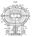
- FIG. 5 is a plan view of the portion shown in FIG. 4.
- FIGS. 6-8 are fragmentary plan views of the portions of the system shown in FIG. 4 and 5, parts being broken away.
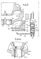
- FIG. 9 is an exploded fragmentary view of a portion of the system shown in Fig. 3.
- FIG. 10 is a diagrammatic plan view of the flow of the coating glass to the orifices
- FIG. 11 is a diagrammatic sectional elevational view of the flow of the coating glass onto the stream being coated.
- FIG. 12 is a fragmentary part diagrammatic sectional view of a portion of the system shown in Fig. 3.
- the invention relates to a method and apparatus for delivering a glass stream comprising a first inner layer and a second outer layer, comprising a generally vertical orifice 20, delivering molten glass from a first source 22 through said orifice 20, and delivering glass from a second source 24 such that the glass from said second source 24 provides an outer layer about the glass from the first source 22 as it flows through said orifice 20.
- Glass sources 22, 24 comprise conventional forehearths.
- An electrical resistance heated delivery tube assembly 30 is provided for delivery of glass from the second source 24 through a refractory orifice ring assembly 32 which combines glass from the source 22 and the source 24 to provide a molten glass with a core of glass from source 22 and an outer layer from source 24.
- the tube assembly 30 includes a tube 34, extending generally vertically, preferably between 19° to 90° from vertical. Upper and lower flanges 36, 38 are secured to the upper and lower ends of said tube 34.
- the tube 34 and flanges 36, 38 are made of a material that is corrosion resistant and can be electrically resistance heated. Platinum and its alloys are the preferred materials. Other materials can be used such as inconel or molybdenum, but these lack glass corrosion and air oxidation resistance offered by platinum at temperatures normally encountered with molten glass applications.
- the tube 34 In operation, it is desired that the tube 34 be heated evenly, but not the flanges 36, 38. This means that the flanges 36, 38 must be a better conductor than the tube 34.
- One way is to make the overall cross-sectional thickness of the flanges 36, 38 much greater than the tube 34.
- Another way is to make flanges 36, 38 from a material with a much higher conductivity than the tube 34. Since the tube 34 must carry a high current at high temperatures and provide corrosion resistance to molten glass, it will be difficult to fabricate a tube/flange structure using dissimilar metals. In practice, any type of glass can be used which in its molten state does not exceed the temperatures limit of the alloy of tube 24.
- the orifice assembly 32 comprises a metal housing assembly 40 including a metal housing pan 42 and three segmented metal tiers 44, 46, 48 about the periphery of the pan 42 (Fig. 9).
- the pan 42 comprises segments 42a-e.
- the lower tier 44 rests on the periphery of pan 42 and comprises segments 44a-44g.
- the intermediate tier 46 rests on the lower tier 44 and comprises segments 46a-g.
- the upper tier 48 rests on the intermediate tier 46 and comprises segments 48a-g.
- the segments in each tier are in abutting relation.
- the segments 44a-g in the lower tier having a length with respect to the intermediate segments 46a-g of the intermediate tier that the segments 46a-g in the intermediate tier 46 are staggered relative the segments 44a-g in the lower tier 44.
- the segments 48a-g in the upper tier 48 have a length relative to the length of the internediate segments 46a-g in the intermediate tier 46 that the segments 48a-g are staggered relative to the segments 46a-g of the intermediate tier 46.
- Boltes 50 extend upwardly through openings in the pan segments of the tier 44 at circumferentially spaced openings and are threaded into the lower tier segments on the pan 42 to retain the segments 42a-g.
- Bolts 52 extend downwardly through the segments of the upper tier 48 and intermediate tier 46 and are threaded into the segments of the lower tier 44.
- the housing assembly 40 supports the orifice castings and burner tile.
- Two layers 54, 56 of insulation board are placed on pan 47.
- Insulation blocks 59 are cast in place over the periphery of layer 56 and ceramic burner tile 58, 60, 62 are stacked to define a combustion chamber C below the lower surface of a lower orifice ring half 64.
- An upper orifice ring half 66 has a peripheral flange 68 that engages an annular shoulder 70 on lower orifice ring half 64.
- the lower surfaces of the lower orifice half 64 serve as an upper wall of the combustion chamber C.
- the housing 40 must support the ceramic orifice castings and burner tile which weigh more than 45,36 kg compared to 4,536 kg or less for a conventional orifice ring. Consequently, the housing assembly 40 is built much heavier than a conventional orifice pan.
- the housing assembly 40 must be essentially rigid to effectively support the brittle refractories. It must also withstand extremes of temperature tc 970° C due to the close proximity of the internal combustion chambers.
- Temperature differences from the inner to outer wall of the housing 40 are typically 260° C or more. Because the housing is several feet across in length or width, thermal expansion differences are significant.
- the separate-segment-concept design allows thermal expansion stresses to dissipate without permanent warpage or buckling. Warpage has proven to damage similar non-segmented orifice housings after one use.
- the tiers of metal housing segments 42, 44, 46, 48 are stacked horizontally in an overlapping and interlocking fashion, and fastened together with the bolts that are vertically oriented. As thermal expansion occurs, the segments can shift slightly, one with respect to the other preventing a cumulative buildup of stress that would cause buckling. The expansion forces are strong and cause the segments to shift despite the clamping forces of the bolts bolding the housing together. Clearances are provided at the ends of the each segment, and around the bolts to prevent binding as the shifting occurs.
- the combustion chamber C includes a horizontal portion 90 that communicates with intermediate tier manifold 46; a downwardly and inwardly extending portion 92 that extends to a horizontal portion 94.
- Axial combustion exhaust openings 96 are defined by holes in the metal pan 42, insulation board 54, 56 and ceramic burner tile 58.
- the lower orifice ring half 64 and upper orifice ring half 66 are herein shown as having three orifices defined by aligned upper and lower openings 100, 102 (FIG. 3). Each opening 102 is defined by a bushing 104 having a flange 106 at its upper end.
- a gap G is provided between the openings 100 and 102 (Fig. 12).
- This separation between the openings 100, 102 is chosen to minimize clogging.
- the resistance to flow derives not only from the separation distance G but from the length L of the passage formed by the flange 106.
- the length L of the passage is the flange width.
- a narrow separation G and small flange L width can present the same resistance to flow as a wider separation and wider flange provided the correct relationships are maintained.
- the separation distance G is also chosen in conjunction with the width of the flange L so that the combination of the separation G and flange width L provides flow resistance sufficient to create a uniform inward flow of casing glass at all points circumferentially around each gap. This results in a concentric distribution of the casing layer to the core glass stream.
- the casing glass must travel longer distances from the inlet through the supply chamber reach points on the far side of the gap. This additional distance could cause more flow resistance and a reduction of casing glass to the far side.
- the design of the metering gap G, the flange width and the supply passages L are chosen in conjunction so that the resistance to flow occurring at the metering gap G is large and the flow resistance within the supply passages 65 is relatively small.
- the gap G is provided between the openings 100, and bushing 104 in opening 102.
- Glass from second source 24 flows into an annular casting glass chamber 108 defined between orifice ring halves 64, 66 (Fig. 11). The glass then flows through the gap G to surround the glass flowing from first source 22 and provide a coated stream of glass that passes downwardly from each opening 102.
- a single orifice ring assembly and delivery system for the coating glass can be installed and may be retrofitted to existing single glass forming processes.
- the design allows multiple glass streams to be combined at the last moment before entering the forming machines. This introduction of glass streams is maintained external to the melting, conditioning and delivery systems of the glass manufacturing process and may be retrofitted to existing installations.
- Prior existing orifice ring designs may be either electrically or gas fired. Of the gas fired versions, the level of heat input has been relatively low due to the difficulty in transferring the heat of combustion into the confined area of the orifice ring.
- the design of the orifice ring assembly embodying the invention yields higher temperatures in the area surrounding the orifice ring than previously attainable with gas/air firing.
- the orifice ring incorporates a ceramic combustion chamber adjacent to the underside of the orifice. The assembly is designed to promote high temperatures within the combustion chamber while using ordinary gas-air mixtures.
- a relatively conventional ceramic orifice ring rests upon a second ring of cast ceramic burner tile shapes.
- the underlying ring of tile forms a hollow burner chamber concentrically surrounding the orifice hole.
- the exposed underside of the upper ring acts as the top surface of the burner chamber so that heat is directly applied to the orifice ring.
- the burner tile ring is segmented to aid construction and minimize cracking from thermal expansion.
- the stack of burner tile pieces and overlying orifice ring are held in a metal housing.
- the relatively heavy metal casing acts as a structural support for the ceramic parts and maintains alignment of the gas supply manifolds with the burner chambers.
- startup of the burner requires a gradual building of fuel input until the combustion chamber becomes incandescent and supports combustion internally.
- the high temperatures and turbulent flow of the combustion gasses within the chamber promote rapid combustion.
- a significant portion of the combustion heat is released within the chamber.
- the high-alumina ceramic chamber lining has a much lower heat transfer rate than a metal liner and consequently develops a higher surface temperature.
- the combustion chamber is backed up by insulation to further reduce beat loss and elevate internal temperatures.
- the internal surfaces of the burner combustion chamber become incandescent during operation and typically reach 1450° C.
- the burner chamber ceramic parts are designed to structurally support the orifice ring which is in a soaking heat environment rather than being cool on the outer side.
- the burner chamber tile contain fuel inlet passages that are relatively long and with abrupt changes in cross-section to cause turbulent flow and impingement of the fuel with the hot ceramic walls for rapid combustion.
- the burner manifolds are purposely set as far outboard radially as possible for cooling.
- the burner tiles are made radially longer than they are high so as to increase the heat transfer path and make the outer edges which contact the manifolds as cool as possible. This minimizes the chance for pre-ignition within the manifolds.
- the long fuel inlet passages in the burner tile serve to both cool the outer edge adjacent to the manifold and preheat the fuel for rapid combustion.
- the present design further includes specific placement of insulation board underneath the burner chamber to both mechanically support the orifice ring inner structure and block heat loss outwardly to the metal casing.
- the area above the burner chamber and near the orifice ring is three graded layers of ceramic castable cements chosen to provide mechanical support of the orifice ring, bond the burner tile edges to seal off combustion gas leaks, and to provide further insulation to block heat loss around the circumference.
Landscapes
- Chemical & Material Sciences (AREA)
- Engineering & Computer Science (AREA)
- Materials Engineering (AREA)
- Organic Chemistry (AREA)
- Glass Melting And Manufacturing (AREA)
- Re-Forming, After-Treatment, Cutting And Transporting Of Glass Products (AREA)
Claims (17)
- Vorrichtung zur Bildung eines Schichtglasstromes mit einer ersten inneren Schicht und einer zweiten äusseren Schicht, wobei die Vorrichtung folgende Merkmale umfasst:dadurch gekennzeichnet,ein erster Düsenring (66) mit mindestens einer ersten Öffnung (100);ein zweiter Düsenring (64) mit mindestens einer zweiten Öffnung (102);ein Spalt (G), der zwischen dem ersten und zweiten Ring (66, 64) zur Bemessung des Mantelglases der äusseren Schicht vorgesehen ist;Mittel einschließlich einer Metallpfanne (42) zur Stützung der ersten und zweiten Düsenringe (66, 64), wobei die erste und zweite Öffnung (100, 102) im Abstand vertikal übereinander ausgerichtet sind und eine Ringkammer (108) zwischen dem ersten und zweiten Düsenring (66, 64) gebildet wird, welche den Spalt (G) umgibt;Mittel zur Lieferung von Kernglas von einer ersten Quelle (22) durch die erste Öffnung (100), undMittel (30) zur Lieferung des Mantelglases von einer zweiten Quelle (24) zur Ringkammer (108), so dass das Glas durch Schwerkraft von der ersten und zweiten Quelle durch die Öffnungen fliesst, um den Schichtglasstrom zu bilden,
dass die Mittel zur Stützung der Düsenringe einen Verteiler (46) für Brennstoff-Luft-Zufuhr aufweist, der am Umfang der Pfanne (42) getragen wird und mit dem zweiten Düsenring (64) zusammen arbeitet, um eine Verbrennungskammer (C) für Brennstoff/Luft zwischen dem zweiten Düsenring (64), der Pfanne (42) und dem Verteiler (46) für Brennstoff-Luft-Zufuhr zu bilden, wobei der Verteiler eine Mehrzahl von Kanälen (47) aufweist, die in die Verbrennungskammer (C) einmünden, um ein Brennstoff/Luft-Gemisch in die Verbrennungskammer zu fördern. - Vorrichtung nach Anspruch 1,
dadurch gekennzeichnet, dass die Verbrennungskammer (C) horizontale Abschnitte (90, 94) und einen sich nach unten erstreckenden Abschnitt (92) aufweist. - Vorrichtung nach Anspruch 1 oder 2,
dadurch gekennzeichnet, dass die Verbrennungskammer (C) zwischen der Unterseite des zweiten Düsenringes (64) und einer Mehrzahl von Brennerblöcken (58, 60, 62) gebildet wird, die von der Pfanne (42) getragen werden. - Vorrichtung nach Anspruch 3,
dadurch gekennzeichnet, dass die Brennerblöcke (58, 60, 62) aus keramischem Material bestehen. - Vorrichtung nach Anspruch 3 oder 4,
dadurch gekennzeichnet, dass die Brennerblöcke (58, 60, 62) den Rand des zweiten Düsenringes (64) mit Bezug auf die Pfanne (42) stützen. - Vorrichtung nach Anspruch 3, 4 oder 5,
dadurch gekennzeichnet, dass Isolationseinrichtungen (54, 56) zwischen den Brennerblöcken (58, 60, 62) und der Pfanne (42) angeordnet sind. - Vorrichtung nach Anspruch 6,
dadurch gekennzeichnet, dass eine Kühlkammereinrichtung (44) sich um den Rand der Pfanne (42) herum benachbart zu den Isoliereinrichtungen (54, 56) erstreckt und den Verteiler (46) für Brennstoff-Luft-Zufuhr mit Bezug auf die Pfanne stützt. - Vorrichtung nach Anspruch 7,
dadurch gekennzeichnet, dass die Pfanne (42), der Verteiler für Brennstoff-Luft-Zufuhr und die Kühlkammereinrichtung (44) jeweils segmentiert sind, um die Wärmedehnung der Mittel zur Stützung der Düsenringe aufzunehmen. - Vorrichtung nach Anspruch 8,
dadurch gekennzeichnet, dass die Segmente der Pfanne (42), des Verteilers (46) für Brennstoff-Luft-Zufuhr und der Kühlkammereinrichtung (44) mit Bezug aufeinander versetzt angeordnet sind. - Vorrichtung nach Anspruch 9,
dadurch gekennzeichnet, dass Ausdehnungsschlitze (42f) in der segmentierten Pfanne (42) vorgesehen sind. - Vorrichtung nach Anspruch 10,
dadurch gekennzeichnet, dass von der Verbrennungskammer (90, 92, 94) ausgehende Abgasöffnungen (96) in der Pfanne (42) vorgesehen sind. - Vorrichtung nach einem der Ansprüche 1 bis 11,
dadurch gekennzeichnet, dass der ringförmige Kühlluftverteiler (44) Segmente (44a bis 44g) aufweist, die auf der Pfanne (42) angeordnet sind und auf dieser gestützt werden. - Vorrichtung nach einem der Ansprüche 1 bis 12,
dadurch gekennzeichnet, dass der ringförmige Verteiler (46) für Brennstoff-Luft-Gemisch in Umfangsrichtung in Segmente (46a bis 46g) aufgeteilt ist, die in Umfangsrichtung des ringförmigen Kühlluftverteilers (44) angeordnet und auf diese gestützt sind. - Vorrichtung nach einem der Ansprüche 1 bis 13,
dadurch gekennzeichnet, dass die Pfanne (42) aus Segmenten (42a bis 42e) hergestellt ist. - Vorrichtung nach Anspruch 14,
dadurch gekennzeichnet, dass der Verteiler für Brennstoff/Luft-Gemisch in der mittleren Lage von drei Segmentlagen (44a bis 44g, 46a bis 46g, 48a bis 48g) gebildet wird, dass jede Reihe der Segmente versetzt und ineinander greifend angeordnet ist und dass die Segmente zur Bildung eines Gehäuseganzen durch vertikale Befestiger (50, 52) befestigt werden, so dass bei der thermischen Ausdehnung die Segmente sich in Umfangsrichtung verschieben können und so den kumulativen Aufbau von Spannungen verhindern können, der zum Ausbeulen führen könnte. - Vorrichtung nach einem der Ansprüche 1 bis 15,
dadurch gekennzeichnet, dass der zweite Düsenring (64) eine Buchse (104) für jede Öffnung (102) umfasst, dass die Buchse (104) einen Flansch (106) aufweist, dass die Breite des jeweiligen Flansches (106) die Strömungslänge (L) durch den Spalt (G) bestimmt und dass die Größe des Spaltes (G) und die Strömungslänge (L) so gewählt werden, dass ein gleichförmiger, nach innen gerichteter Strom des Mantelglases an allen Stellen des Umfangs des Spaltes (G) geschaffen wird. - Verfahren zur Bildung eines Schichtglasstroms mit der Vorrichtung nach einem der Ansprüche 1 bis 16, mit folgenden Schritten:(a) die Ringkammer (108) wird erhitzt, indem ein Brennstoff/Luft-Gemisch in den Verteiler für Brennstoffluft gerichtet wird;(b) geschmolzenes Kernglas wird durch die erste Öffnung (100) zugeführt;(c) geschmolzenes Mantelglas wird der ringförmigen Kammer (108) zugeführt, von wo aus das Glas radial durch den Spalt (G) in die zweite Öffnung (102) fließt.
Applications Claiming Priority (2)
| Application Number | Priority Date | Filing Date | Title |
|---|---|---|---|
| US374372 | 1982-05-03 | ||
| US37437295A | 1995-01-18 | 1995-01-18 |
Publications (3)
| Publication Number | Publication Date |
|---|---|
| EP0722908A2 EP0722908A2 (de) | 1996-07-24 |
| EP0722908A3 EP0722908A3 (de) | 1996-10-30 |
| EP0722908B1 true EP0722908B1 (de) | 2001-06-13 |
Family
ID=23476525
Family Applications (1)
| Application Number | Title | Priority Date | Filing Date |
|---|---|---|---|
| EP96100613A Expired - Lifetime EP0722908B1 (de) | 1995-01-18 | 1996-01-17 | Verfahren und Vorrichtung zum Abgeben eines Schichtglasstromes zum Herstellen von Glaskübeln |
Country Status (10)
| Country | Link |
|---|---|
| US (2) | US5855640A (de) |
| EP (1) | EP0722908B1 (de) |
| JP (1) | JP3952217B2 (de) |
| AU (1) | AU700339B2 (de) |
| CA (1) | CA2167473C (de) |
| DE (1) | DE69613249T2 (de) |
| ES (1) | ES2158152T3 (de) |
| HU (1) | HU214929B (de) |
| PL (1) | PL181933B1 (de) |
| ZA (1) | ZA96405B (de) |
Families Citing this family (16)
| Publication number | Priority date | Publication date | Assignee | Title |
|---|---|---|---|---|
| US5810900A (en) * | 1995-01-18 | 1998-09-22 | Owens-Brockway Glass Container Inc. | Method and apparatus for delivering a cased glass stream |
| US5868812A (en) * | 1996-09-20 | 1999-02-09 | Owens-Brockway Glass Container Inc. | Method and apparatus for delivering a cased glass stream |
| US5735925A (en) * | 1996-09-20 | 1998-04-07 | Owens-Brockway Glass Container Inc. | Method and apparatus for delivering a cased glass stream |
| US5935286A (en) * | 1997-03-21 | 1999-08-10 | Owens-Brockway Glass Container Inc. | Method and apparatus for delivering a cased glass stream |
| US5944863A (en) * | 1997-04-11 | 1999-08-31 | Owens-Brockway Glass Container Inc. | Apparatus for controlling flow of casing glass in a cased glass stream |
| US5853447A (en) * | 1997-04-14 | 1998-12-29 | Owens-Brockway Glass Container Inc. | Method and apparatus for delivering a cased glass stream |
| US5803942A (en) * | 1997-04-14 | 1998-09-08 | Owens-Brockway Glass Container Inc. | Method and apparatus for delivering a cased glass stream |
| CA2244306C (en) | 1997-07-31 | 2004-03-09 | Owens-Brockway Glass Container Inc. | Method and apparatus for delivering a cased glass stream |
| US5906666A (en) * | 1997-12-16 | 1999-05-25 | Owens-Brockway Glass Container Inc. | Method and apparatus for delivering a cased glass stream having improved resistance to high-temperature erosion |
| NL1007932C2 (nl) * | 1997-12-30 | 1999-07-01 | Standard Group Holding Bv | Werkwijze voor het vervaardigen van successieve bolvormige glazen voorwerpen met daarin opgenomen driedimensionale voorwerpen. |
| DE19948634B4 (de) * | 1999-10-01 | 2005-02-03 | Reeßing, Friedrich, Dr.rer.nat. | Konditioniereinrichtung für geschmolzenes Glas mit optimierter elektrischer Beheizung und verbesserter thermischer Homogenität des Glases |
| US6457330B1 (en) | 1999-12-06 | 2002-10-01 | Owens-Brockway Glass Container Inc. | Apparatus and method for delivering a cased glass stream |
| US6652935B1 (en) * | 2000-02-28 | 2003-11-25 | Owens-Brookway Glass Container Inc. | Flint/amber laminated glass container and method of manufacture |
| US6634187B1 (en) * | 2000-11-15 | 2003-10-21 | Owens-Brockway Glass Container Inc. | Apparatus for delivering a cased glass stream having a raised and sealed orifice bushing |
| DE102005019646C5 (de) * | 2005-04-26 | 2020-04-30 | AGC Inc. | Vorrichtung zum Überführen von Glasschmelze auf ein Floatbad |
| CN101157593B (zh) | 2007-03-07 | 2010-09-22 | 中国科学院大连化学物理研究所 | 由甲醇或/和二甲醚生产低碳烯烃的方法 |
Family Cites Families (40)
| Publication number | Priority date | Publication date | Assignee | Title |
|---|---|---|---|---|
| US1605797A (en) * | 1926-11-02 | s-l tyson | ||
| US1622666A (en) * | 1925-03-31 | 1927-03-29 | Hartford Empire Co | Apparatus for feeding molten glass |
| US1828217A (en) * | 1928-12-12 | 1931-10-20 | Hartford Empire Co | Method of and apparatus for feeding molten glass |
| US2765586A (en) * | 1952-10-23 | 1956-10-09 | Corning Glass Works | Manufacture of glass tubing |
| US3015842A (en) * | 1954-01-25 | 1962-01-09 | Owens Corning Fiberglass Corp | Apparatus for producing fibers |
| US3078695A (en) * | 1958-04-23 | 1963-02-26 | Kimble Glass Co | Apparatus for extruding glass |
| US3219426A (en) * | 1961-09-14 | 1965-11-23 | Owens Illinois Glass Co | Apparatus and method for drawing glass tubes, rods, or the like |
| FR1328512A (fr) * | 1962-04-19 | 1963-05-31 | Louyot Comptoir Lyon Alemand | Perfectionnement aux appareils et pièces métalliques soumis au contact de matériaux fondus à haute température |
| US3288583A (en) * | 1962-06-07 | 1966-11-29 | Bausch & Lomb | Apparatus for producing optical fiber |
| US3291584A (en) * | 1963-06-20 | 1966-12-13 | Bausch & Lomb | Fiber glass orifice |
| US3508904A (en) * | 1965-04-29 | 1970-04-28 | Owens Illinois Inc | Glass feeding orifice with multichamber combustion zones |
| US3531268A (en) * | 1966-11-08 | 1970-09-29 | Corning Glass Works | Heated delivery tip for liquid glass |
| US3582299A (en) * | 1967-11-06 | 1971-06-01 | Robert T Gladwell Jr | Multiple delivery tip for liquid glass |
| US3607184A (en) * | 1968-04-12 | 1971-09-21 | Owens Illinois Inc | Method and apparatus for drawing a devitrifiable glass at a temperature below the liquidus temperature |
| US3554726A (en) * | 1968-07-11 | 1971-01-12 | Emhart Corp | Glass feeding apparatus with orifice plate support frame and lifting means therefor |
| US3580713A (en) * | 1968-11-29 | 1971-05-25 | Owens Illinois Inc | Apparatus for feeding glass |
| US3625671A (en) * | 1969-01-06 | 1971-12-07 | Owens Illinois Inc | Apparatus for feeding glass having multiple outlets |
| US3589879A (en) * | 1969-04-25 | 1971-06-29 | Petr Grigorievich Yantsev | Device for supplying glass melt from the feeder of a glass furnace into the glass fiber formation zone |
| US3622289A (en) * | 1969-12-12 | 1971-11-23 | Owens Corning Fiberglass Corp | Glass feeder made of pt-rh-mo high temperature-high strength alloy |
| US3899315A (en) * | 1974-04-15 | 1975-08-12 | American Optical Corp | Method of making glass clad glass lenses |
| DE2539039A1 (de) * | 1975-09-02 | 1977-03-10 | Kalenborn Dr Schmelzbasaltwerk | Einlaufrinne |
| US3960530A (en) * | 1975-07-28 | 1976-06-01 | Northern Electric Company Limited | Method of coating a glass fiber filament |
| US4023953A (en) * | 1975-08-07 | 1977-05-17 | Corning Glass Works | Apparatus and method for producing composite glass tubing |
| US4217123A (en) * | 1976-02-03 | 1980-08-12 | International Standard Electric Corporation | Double crucible method of optical fiber manufacture |
| DE2629658A1 (de) * | 1976-07-01 | 1978-01-05 | Siemens Ag | Vorrichtung und verfahren zur herstellung von lichtleitfasern mit lose sitzender ummantelung aus glas |
| US4299609A (en) * | 1977-09-27 | 1981-11-10 | Siemens Aktiengesellschaft | Optical unit having a longitudinal side coupling zone |
| DE2842505C2 (de) * | 1978-09-29 | 1980-07-17 | Kernforschungszentrum Karlsruhe Gmbh, 7500 Karlsruhe | Verfahren zum chargenweisen Ablassen einer Borosilikatglasschmelze aus einem keramischen Glasschmelzofen mit beheiztem Bodenauslauf und Einrichtung zur Durchführung des Verfahrens |
| GB2043049B (en) * | 1979-02-27 | 1983-06-15 | Wiederaufarbeitung Von Kernbre | Method for controlling the discharge of molten material |
| US4247320A (en) * | 1979-09-14 | 1981-01-27 | Corning Glass Works | Glass conditioning |
| US4305747A (en) * | 1980-07-07 | 1981-12-15 | Owens-Illinois, Inc. | Multiple gob glass feeder system and method of operation |
| US4381932A (en) * | 1981-05-01 | 1983-05-03 | Corning Glass Works | Laminated gob for pressing glass articles |
| US4457771A (en) * | 1981-05-01 | 1984-07-03 | Corning Glass Works | Forming laminated articles from a composite encapsulated charge of molten glass |
| NL8102878A (nl) * | 1981-06-16 | 1983-01-17 | Philips Nv | Werkwijze voor de continue fabricage van optische vezels met behulp van de dubbele kroesmethode, vezels verkregen met deze werkwijze en dubbele kroes voor toepassing in deze werkwijze. |
| US4875917A (en) * | 1986-10-31 | 1989-10-24 | Corning Incorporated | Method for making a layered glass article |
| US4740401A (en) * | 1987-02-02 | 1988-04-26 | Owens-Illinois Glass Container Inc. | Forming laminated glass containers from a composite encapsulated gob of molten glass |
| DE3843425A1 (de) * | 1988-12-23 | 1990-06-28 | Schott Glaswerke | Verfahren und vorrichtung zum maschinellen herstellen von hohlglaskoerpern |
| US4897100A (en) * | 1989-01-13 | 1990-01-30 | Owens-Corning Fiberglas Corporation | Apparatus and process for fiberizing fluoride glasses using a double crucible and the compositions produced thereby |
| US5204120A (en) * | 1989-10-31 | 1993-04-20 | Hoover Universal, Inc. | Intermittent multi-layer multi-parison extrusion head |
| US5229194A (en) * | 1991-12-09 | 1993-07-20 | Guardian Industries Corp. | Heat treatable sputter-coated glass systems |
| FR2703042B1 (fr) * | 1993-03-23 | 1995-06-09 | Saint Gobain Vitrage Int | Canal d'ecoulement pour le transfert du verre en fusion. |
-
1996
- 1996-01-16 AU AU42035/96A patent/AU700339B2/en not_active Ceased
- 1996-01-16 HU HU9600089A patent/HU214929B/hu not_active IP Right Cessation
- 1996-01-17 EP EP96100613A patent/EP0722908B1/de not_active Expired - Lifetime
- 1996-01-17 CA CA002167473A patent/CA2167473C/en not_active Expired - Fee Related
- 1996-01-17 DE DE69613249T patent/DE69613249T2/de not_active Expired - Fee Related
- 1996-01-17 ES ES96100613T patent/ES2158152T3/es not_active Expired - Lifetime
- 1996-01-18 ZA ZA96405A patent/ZA96405B/xx unknown
- 1996-01-18 PL PL96312375A patent/PL181933B1/pl not_active IP Right Cessation
- 1996-01-18 JP JP03702896A patent/JP3952217B2/ja not_active Expired - Fee Related
-
1997
- 1997-01-10 US US08/782,552 patent/US5855640A/en not_active Expired - Fee Related
-
1998
- 1998-08-27 US US09/141,092 patent/US5914438A/en not_active Expired - Fee Related
Also Published As
| Publication number | Publication date |
|---|---|
| ZA96405B (en) | 1996-08-16 |
| DE69613249T2 (de) | 2002-04-11 |
| JPH0920520A (ja) | 1997-01-21 |
| CA2167473C (en) | 2007-01-16 |
| AU700339B2 (en) | 1998-12-24 |
| AU4203596A (en) | 1996-07-25 |
| CA2167473A1 (en) | 1996-07-19 |
| US5855640A (en) | 1999-01-05 |
| ES2158152T3 (es) | 2001-09-01 |
| HUP9600089A2 (en) | 1997-02-28 |
| HUP9600089A3 (en) | 1997-08-28 |
| HU214929B (hu) | 1998-07-28 |
| EP0722908A3 (de) | 1996-10-30 |
| DE69613249D1 (de) | 2001-07-19 |
| US5914438A (en) | 1999-06-22 |
| HU9600089D0 (en) | 1996-03-28 |
| PL312375A1 (en) | 1996-07-22 |
| JP3952217B2 (ja) | 2007-08-01 |
| EP0722908A2 (de) | 1996-07-24 |
| PL181933B1 (pl) | 2001-10-31 |
Similar Documents
| Publication | Publication Date | Title |
|---|---|---|
| EP0722908B1 (de) | Verfahren und Vorrichtung zum Abgeben eines Schichtglasstromes zum Herstellen von Glaskübeln | |
| US6669988B2 (en) | Hardware assembly for CVI/CVD processes | |
| EP0792385B1 (de) | Vorrichtung zur durchführung des gasphaseninfiltrations bzw.-beschichtungsverfahren | |
| RU2315821C2 (ru) | Подогреватель газа | |
| US6846514B2 (en) | Gas port sealing for CVD/CVI furnace hearth plates | |
| US3995665A (en) | Thermal insulation element | |
| EP0301763B1 (de) | Stranggiessofen und Giessformanordnung in austauschbarer Funktionseinheit | |
| US5251882A (en) | Liquid-carrying cooling element for shaft furnaces | |
| EP0831068B1 (de) | Verfahren und Vorrichtung zum Abgeben eines überfangenen Glasstromes | |
| US4107449A (en) | Water-cooled roof of electric-arc furnace | |
| EA003117B1 (ru) | Литейная форма для производства охлаждающего элемента и охлаждающий элемент, изготовленный в указанной форме | |
| US4432791A (en) | Ceramic radiant tube heated aluminum melter and method of melting aluminium | |
| JPH059379B2 (de) | ||
| JP2011520084A (ja) | quarlブロックとインジェクタとを具備した燃焼ツール、前記ツールのアセンブリおよび前記ツールを備えた炉 | |
| US3050813A (en) | Method of producing a combined radiant heat fuel burner block and refractory cup | |
| JP2922482B2 (ja) | 色着せガラス流を供給する方法および装置 | |
| GB2052029A (en) | Furnace with Reduced Heat Loss | |
| WO2019147920A1 (en) | Stave with external manifold | |
| JPH0238906Y2 (de) | ||
| JPH0428826A (ja) | 焼結機の点火装置 | |
| SU1235904A1 (ru) | Лещадь доменной печи | |
| JPS61291425A (ja) | 管状ガラス部材の加熱装置 |
Legal Events
| Date | Code | Title | Description |
|---|---|---|---|
| PUAI | Public reference made under article 153(3) epc to a published international application that has entered the european phase |
Free format text: ORIGINAL CODE: 0009012 |
|
| AK | Designated contracting states |
Kind code of ref document: A2 Designated state(s): DE ES FR GB IT |
|
| PUAL | Search report despatched |
Free format text: ORIGINAL CODE: 0009013 |
|
| AK | Designated contracting states |
Kind code of ref document: A3 Designated state(s): DE ES FR GB IT |
|
| 17P | Request for examination filed |
Effective date: 19970407 |
|
| 17Q | First examination report despatched |
Effective date: 19990625 |
|
| GRAG | Despatch of communication of intention to grant |
Free format text: ORIGINAL CODE: EPIDOS AGRA |
|
| GRAG | Despatch of communication of intention to grant |
Free format text: ORIGINAL CODE: EPIDOS AGRA |
|
| GRAH | Despatch of communication of intention to grant a patent |
Free format text: ORIGINAL CODE: EPIDOS IGRA |
|
| GRAH | Despatch of communication of intention to grant a patent |
Free format text: ORIGINAL CODE: EPIDOS IGRA |
|
| GRAA | (expected) grant |
Free format text: ORIGINAL CODE: 0009210 |
|
| ITF | It: translation for a ep patent filed | ||
| AK | Designated contracting states |
Kind code of ref document: B1 Designated state(s): DE ES FR GB IT |
|
| REF | Corresponds to: |
Ref document number: 69613249 Country of ref document: DE Date of ref document: 20010719 |
|
| ET | Fr: translation filed | ||
| REG | Reference to a national code |
Ref country code: ES Ref legal event code: FG2A Ref document number: 2158152 Country of ref document: ES Kind code of ref document: T3 |
|
| REG | Reference to a national code |
Ref country code: GB Ref legal event code: IF02 |
|
| PLBE | No opposition filed within time limit |
Free format text: ORIGINAL CODE: 0009261 |
|
| STAA | Information on the status of an ep patent application or granted ep patent |
Free format text: STATUS: NO OPPOSITION FILED WITHIN TIME LIMIT |
|
| 26N | No opposition filed | ||
| PGFP | Annual fee paid to national office [announced via postgrant information from national office to epo] |
Ref country code: GB Payment date: 20061213 Year of fee payment: 12 |
|
| PGFP | Annual fee paid to national office [announced via postgrant information from national office to epo] |
Ref country code: ES Payment date: 20070124 Year of fee payment: 12 |
|
| PGFP | Annual fee paid to national office [announced via postgrant information from national office to epo] |
Ref country code: DE Payment date: 20070131 Year of fee payment: 12 |
|
| PGFP | Annual fee paid to national office [announced via postgrant information from national office to epo] |
Ref country code: IT Payment date: 20070523 Year of fee payment: 12 |
|
| PGFP | Annual fee paid to national office [announced via postgrant information from national office to epo] |
Ref country code: FR Payment date: 20070103 Year of fee payment: 12 |
|
| GBPC | Gb: european patent ceased through non-payment of renewal fee |
Effective date: 20080117 |
|
| PG25 | Lapsed in a contracting state [announced via postgrant information from national office to epo] |
Ref country code: DE Free format text: LAPSE BECAUSE OF NON-PAYMENT OF DUE FEES Effective date: 20080801 |
|
| REG | Reference to a national code |
Ref country code: FR Ref legal event code: ST Effective date: 20081029 |
|
| PG25 | Lapsed in a contracting state [announced via postgrant information from national office to epo] |
Ref country code: GB Free format text: LAPSE BECAUSE OF NON-PAYMENT OF DUE FEES Effective date: 20080117 |
|
| REG | Reference to a national code |
Ref country code: ES Ref legal event code: FD2A Effective date: 20080118 |
|
| PG25 | Lapsed in a contracting state [announced via postgrant information from national office to epo] |
Ref country code: FR Free format text: LAPSE BECAUSE OF NON-PAYMENT OF DUE FEES Effective date: 20080131 |
|
| PG25 | Lapsed in a contracting state [announced via postgrant information from national office to epo] |
Ref country code: ES Free format text: LAPSE BECAUSE OF NON-PAYMENT OF DUE FEES Effective date: 20080118 |
|
| PG25 | Lapsed in a contracting state [announced via postgrant information from national office to epo] |
Ref country code: IT Free format text: LAPSE BECAUSE OF NON-PAYMENT OF DUE FEES Effective date: 20080117 |