EP0721893A1 - Container with tray system for storing objects - Google Patents
Container with tray system for storing objects Download PDFInfo
- Publication number
- EP0721893A1 EP0721893A1 EP95120335A EP95120335A EP0721893A1 EP 0721893 A1 EP0721893 A1 EP 0721893A1 EP 95120335 A EP95120335 A EP 95120335A EP 95120335 A EP95120335 A EP 95120335A EP 0721893 A1 EP0721893 A1 EP 0721893A1
- Authority
- EP
- European Patent Office
- Prior art keywords
- insert system
- insert
- receptacles
- shelf
- container
- Prior art date
- Legal status (The legal status is an assumption and is not a legal conclusion. Google has not performed a legal analysis and makes no representation as to the accuracy of the status listed.)
- Granted
Links
Images


Classifications
-
- B—PERFORMING OPERATIONS; TRANSPORTING
- B65—CONVEYING; PACKING; STORING; HANDLING THIN OR FILAMENTARY MATERIAL
- B65D—CONTAINERS FOR STORAGE OR TRANSPORT OF ARTICLES OR MATERIALS, e.g. BAGS, BARRELS, BOTTLES, BOXES, CANS, CARTONS, CRATES, DRUMS, JARS, TANKS, HOPPERS, FORWARDING CONTAINERS; ACCESSORIES, CLOSURES, OR FITTINGS THEREFOR; PACKAGING ELEMENTS; PACKAGES
- B65D43/00—Lids or covers for rigid or semi-rigid containers
- B65D43/14—Non-removable lids or covers
- B65D43/16—Non-removable lids or covers hinged for upward or downward movement
- B65D43/163—Non-removable lids or covers hinged for upward or downward movement the container and the lid being made separately
- B65D43/169—Non-removable lids or covers hinged for upward or downward movement the container and the lid being made separately the lid, the hinge and the element connecting them to the container being made of one piece
-
- B—PERFORMING OPERATIONS; TRANSPORTING
- B25—HAND TOOLS; PORTABLE POWER-DRIVEN TOOLS; MANIPULATORS
- B25H—WORKSHOP EQUIPMENT, e.g. FOR MARKING-OUT WORK; STORAGE MEANS FOR WORKSHOPS
- B25H3/00—Storage means or arrangements for workshops facilitating access to, or handling of, work tools or instruments
- B25H3/02—Boxes
- B25H3/021—Boxes comprising a number of connected storage elements
- B25H3/023—Boxes comprising a number of connected storage elements movable relative to one another for access to their interiors
-
- B—PERFORMING OPERATIONS; TRANSPORTING
- B25—HAND TOOLS; PORTABLE POWER-DRIVEN TOOLS; MANIPULATORS
- B25H—WORKSHOP EQUIPMENT, e.g. FOR MARKING-OUT WORK; STORAGE MEANS FOR WORKSHOPS
- B25H3/00—Storage means or arrangements for workshops facilitating access to, or handling of, work tools or instruments
- B25H3/06—Trays
-
- B—PERFORMING OPERATIONS; TRANSPORTING
- B65—CONVEYING; PACKING; STORING; HANDLING THIN OR FILAMENTARY MATERIAL
- B65D—CONTAINERS FOR STORAGE OR TRANSPORT OF ARTICLES OR MATERIALS, e.g. BAGS, BARRELS, BOTTLES, BOXES, CANS, CARTONS, CRATES, DRUMS, JARS, TANKS, HOPPERS, FORWARDING CONTAINERS; ACCESSORIES, CLOSURES, OR FITTINGS THEREFOR; PACKAGING ELEMENTS; PACKAGES
- B65D21/00—Nestable, stackable or joinable containers; Containers of variable capacity
- B65D21/02—Containers specially shaped, or provided with fittings or attachments, to facilitate nesting, stacking, or joining together
- B65D21/0201—Containers specially shaped, or provided with fittings or attachments, to facilitate nesting, stacking, or joining together stackable or joined together side-by-side
-
- B—PERFORMING OPERATIONS; TRANSPORTING
- B65—CONVEYING; PACKING; STORING; HANDLING THIN OR FILAMENTARY MATERIAL
- B65D—CONTAINERS FOR STORAGE OR TRANSPORT OF ARTICLES OR MATERIALS, e.g. BAGS, BARRELS, BOTTLES, BOXES, CANS, CARTONS, CRATES, DRUMS, JARS, TANKS, HOPPERS, FORWARDING CONTAINERS; ACCESSORIES, CLOSURES, OR FITTINGS THEREFOR; PACKAGING ELEMENTS; PACKAGES
- B65D21/00—Nestable, stackable or joinable containers; Containers of variable capacity
- B65D21/02—Containers specially shaped, or provided with fittings or attachments, to facilitate nesting, stacking, or joining together
- B65D21/04—Open-ended containers shaped to be nested when empty and to be superposed when full
- B65D21/043—Identical stackable containers specially adapted for nesting after rotation around a vertical axis
- B65D21/046—Identical stackable containers specially adapted for nesting after rotation around a vertical axis about 90°
-
- B—PERFORMING OPERATIONS; TRANSPORTING
- B65—CONVEYING; PACKING; STORING; HANDLING THIN OR FILAMENTARY MATERIAL
- B65D—CONTAINERS FOR STORAGE OR TRANSPORT OF ARTICLES OR MATERIALS, e.g. BAGS, BARRELS, BOTTLES, BOXES, CANS, CARTONS, CRATES, DRUMS, JARS, TANKS, HOPPERS, FORWARDING CONTAINERS; ACCESSORIES, CLOSURES, OR FITTINGS THEREFOR; PACKAGING ELEMENTS; PACKAGES
- B65D25/00—Details of other kinds or types of rigid or semi-rigid containers
- B65D25/02—Internal fittings
- B65D25/04—Partitions
Definitions
- the invention relates to an insert system for containers used for storing objects, which have a box-shaped or bowl-shaped lower part provided with an access opening, with at least one insert which can be inserted into the lower part and which has a plurality of storage chambers lying next to one another.
- the insert having the storage chambers is designed as a deep-drawn, one-piece plastic part, into which the storage chambers are molded.
- the storage chambers are designed to match the objects to be stored.
- the insert is composed of a plurality of receptacles, which are arranged next to one another and are referred to as boxes. These receptacles can be used and removed individually, resulting in greater flexibility. However, if a container equipped in this way is required from time to time for another purpose that requires the temporary removal of the insert, the necessary moving of the individual receptacles is very time-consuming, and the subsequent reinstallation is the same, especially with differently designed receptacles, a puzzle.
- the insert is composed of at least one shelf provided with at least one carrying handle and a partitioning device which is detachably placed on the shelf and has dividing walls for forming the storage chambers.
- the subdivision device consists at least partially and preferably completely of a grid structure in a cross design, which lies on the shelf, the shelf forming the bottom of the compartments defined here.
- the subdivision device consists at least partially and preferably completely of a plurality of individual ones on the Tray of storage containers placed next to each other, each containing at least one storage chamber, and the container walls of which form the partition walls.
- Appropriate or differently designed receptacles can be placed on the tray in an appropriate arrangement and handled together with the tray. In order to remove all of the receptacles of the insert from a container, for example a case-like one, it is sufficient to grasp the tray on the at least one carrying handle and lift it out of the lower part.
- the receptacles are expediently box-shaped and have a loading and removal opening on the top, which enables the objects to be stored to be inserted or removed. This results in good accessibility when the lid of the container equipped with the insert is open.
- At least one anchoring recess which enables an additional part, for example a label or a sealing cover, to be anchored.
- the shelf expediently has a preferably circumferential, protruding boundary edge, which can result in a tray-like design.
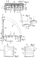
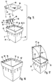
- FIG. 1 show, in different variants, an insert system which has one or more inserts 1 which can be removed and inserted into a container 2.
- a respective insert 1 comprises a tray 3 and a dividing device 4 of different designs which can be removably arranged on the tray 3.
- a preferred design of the subdivision device 4, 4 ' is composed of a multiple arrangement of receptacles 5 which can be individually placed next to one another on the tray. These receptacles 5 can also be used by themselves independently of an insert 1 for storing objects.
- a subdivision device 4, 4 ′′ of a different type (FIG. 1) consists of a coherent lattice structure 6, which can be placed on the tray 3 and has a compartment division.
- the one or more inserts 1 are basically designed so that they can be used in similar containers of different heights, with the possibility of vertical stacking, the inserts being able to have different heights.
- the exemplary type of container 2 has a box-shaped or bowl-shaped lower part 7 with a rectangular plan.
- the lower part 7 has a rectangularly contoured bottom wall 8 and four lateral, towering boundary walls 12.
- the edge 15 delimits an access opening 13 to which a cover 14 is assigned.
- the access opening 13 can thus be kept open or closed as required.
- the lid 14 is expediently a swivel lid. In the exemplary embodiment, it is pivotably mounted on the edge of the rear wall 12 'of the lower part 7.
- Fig. 1 shows it in the swung open position, which allows access to the interior 16 of the lower part 7 from the outside.
- 2 shows it in the closed position folded down on the edge 15, in which the interior 16 is closed all around.
- locking members 17 enable a releasable locking of the cover 4 in the closed position.
- the closure members 17 make it possible to lock a plurality of containers 2 stacked one on top of the other, as is described in detail in EP 0 555 533 B1, so that there is no need to go into this at this point.
- a particularly pivotable handle 18 is arranged on the outside of the cover 14, with the aid of which the closed container 2 can be easily transported.
- the interior 16 of the lower part 7 and an adjoining interior 16 'of the cover 14 in the closed position together form a receiving space 22 for one or more inserts 1.
- the number of inserts 1 to be accommodated in the receiving space 22 depends on the height of the receiving space 22 and the amount of the stakes 1. Variable dimensions are possible here. If several inserts 1 are accommodated in the receiving space 22 of a container 2 at the same time, they assume a stacking position, as can be seen from FIGS. 2, 5 and 6. The inserts 1 are stacked here in the vertical direction. A comparison of FIGS. 5 and 6 shows that one and the same container 2 optionally with inserts 1 of different heights and different stacking order
- the equipment depends on the individual need. The user can have a plurality of reserve inserts ready so that he can equip the container 2 with different inserts as required and is very flexible.
- FIGS. 2 and 3 A comparison of FIGS. 2 and 3 makes it clear that one and the same container 2, for example with two stacked inserts 1 (FIG. 2) or with only a single insert 1, which has twice the height as a respective one of the aforementioned inserts (FIG. 3), can be equipped.
- Each insert 1 includes a tray-shaped tray 3 in the exemplary embodiment. Its plan is adapted to that of the receiving space 22 so that it can be inserted into the lower part 7 from above, in the inserted state laterally between the tray 3 and the lateral boundary walls 12 of the lower part 7 there is only a small scope, so that the inserted tray 3 is fixed in the transverse direction and prevented from slipping. For reasons of space economy, efforts will be made to bring the base area of the tray 3 as close as possible to that of the interior space 16.
- the shelf 3 has a plate-like base 23 with a rectangular contour and preferably a circumferential, protruding boundary edge 24. This boundary edge 24 delimits the usable space 25 of the shelf 3.
- the tray 3 has several carrying handles 26.
- there are two carrying handles 26 which are located in the area of two diametrically opposite sections of the boundary edge 24. They are expediently arranged on the narrow side edges of the shelf, whereby they protrude upwards and protrude beyond the boundary edge 24.
- the carrying handles 26 are arranged on the outer surface of the sections of the boundary edge 24 arranged on the narrow side. They are therefore outside the usable floor space 25. When viewed in side view according to FIGS. 2 and 3, they have, for example, an essentially U-shaped design, the U opening pointing downward. The interior of the U widens towards the U opening. In this way, when the trays 3 are in the stacked position, the trays 3 which are directly adjacent to one another interlock with one another in the vertical direction with their carrying handles 26.
- the respective upper tray 3 can hereby with its bottom 23 on the upward-facing terminating edge 29
- the boundary edge 24 has in particular the shape of a circumferential band.
- the tray 3 is preferably a one-piece plastic part which is produced in a casting process.
- the dividing device 4 arranged on the shelf forms a plurality of storage chambers 28 which are arranged in a plane parallel to the floor 23 of the associated shelf are arranged next to one another. Partitions 32 aligned in the vertical direction ensure spatial separation between the individual storage chambers 28.
- the partition walls 32 are formed by the individual lattice elements running between two lattice nodes.
- it is a cross grille with a right-angled arrangement of the grating longitudinal elements 33 and the grating transverse elements 34. This results in square or rectangularly contoured bottomless compartments which are covered by the bottom 23 of the tray at the bottom in the use position arranged on the tray 3 that the storage chambers 28 result.
- the edge-side end walls of the storage chambers 28 are expediently formed by the circumferential boundary edge 24 which, in cooperation with the end faces of the longitudinal and transverse elements 33, 34, ensures that the dividing device 4 ′′ is fixed in position.
- the storage chambers 28 are formed by the interior of the receptacles 5, the lateral ones thereof Boundary walls 35 which form partitions 32.
- the multiple arrangement of the receptacles 5 results in adjacent storage chambers 28 being separated from one another by two partitions.
- the example receptacle 5 have a rectangular plan (Fig. 7 and 12) with different side lengths. Above the rectangularly contoured bottom 36 is a loading and removal opening 37, through which the objects to be stored are inserted, filled or removed.
- the storage chambers 28 are suitable, depending on the design, for storing a wide variety of objects, be it individual larger objects such as transportable processing machines or bulk goods such as screws, nails, dowels or the like.
- all the receptacles 5 placed on a tray 3 can be of identical design or at least have the same base area.
- a base size for the receptacles 5 is expediently present, which occurs in the present case in the receptacles 5 shown in FIG. 7, a certain base length and a certain base width being present.
- a further row 38 ′ running parallel thereto contains only one receptacle 5 with the base width and an integer multiple of the base length, here being five times the base length. Between these two rows 38, 38 'there is a receptacle 5' with a multiple integer multiple of both the base width and the base length, here twice in each case. The remaining space is filled with three additional receptacles, the first of which has the base length and the base width. The second and third receptacles each have the base width, in one case, however, twice the base length and in the other case, three times the base length.
- receptacles 5 which are specially adapted to the object to be accommodated.
- the receptacles 5 can have an L shape, a T shape or an H shape, for example.
- the height of the boundary edge 24 such that it is surmounted above by the subdivision device 4 or its individual elements.
- a respective upper shelf 3 can be seated on the subdivision device 4 arranged underneath, its bottom 23 acting as a cover for the storage chambers 28 underneath.
- the subdivision device 4 is thus fixed vertically and objects are prevented from falling out.
- the dividing device 4 can be easily gripped and lifted out at the projecting section.
- FIG. 3 a preferably plate-shaped swivel cover 42 is attached to the tray 3 of the insert 1 in question. It is pivotally mounted on one of the four sections of the boundary edge 24, so that it can be pivoted according to double arrow 41 between a closed position covering the usable surface area 25 and a folded open position shown in FIG. 3.
- the swivel mounting of the swivel cover 42 takes place on a hook arrangement 43, which is integrally formed in the region of the longitudinal edge of the relevant section of the boundary edge 24 and into which the swivel cover 42 is expediently engaged with a bearing axis 44.
- the hook arrangement 43 is expediently located on a longitudinal section of the boundary edge 24.
- the hook arrangement 43 can be used to hang the relevant insert on the edge of the lateral boundary wall 12 of the lower part 7, as shown in FIG. 4.
- the shelf 3 carrying the dividing device 4 is located outside the lower part 7, and in the present case it can be attached to the front wall 12 ′′. In this way, a lower part 7 located underlying insert 44 made accessible without having to place the raised insert 45 on the floor.
- a soft material layer 46 can be applied to the inner surface of the lid 14 (FIG. 2). It is e.g. glued on. When the cover 14 is in the closed position, it rests on the upper insert 1 and exerts a slight pressure. It preferably consists of a foam material. If the upper insert does not have a cover, the soft material layer 46 also covers or closes the storage chambers 28 which are open at the top.
- a fixation of the inserts 1 contained in the container 2 in the vertical direction can also be achieved in that fixing means 47 are present on the lid 14, which work together with the single or overhead tray 3.
- fixing means 47 designed as fixing lugs which cooperate with the carrying handles 26.
- the supporting webs 27 of the carrying handles 26 have one or more downwardly directed depressions 48, into which the fixing lugs 47 are immersed and, through cooperation with the base of the depressions 48, ensure that that the existing trays 3 cannot lift off the bottom wall 8 of the container 2.
- the fixing means 47 are located in the region of the narrow edge of the cover 14 (FIG. 1) and have a tab-like shape. By connecting the peripheral edge of the cover 14 to the upper cover wall, they simultaneously cause the cover 14 to stiffen.
- FIGS. 9 and 10 Another component of the insert system can be a profile strip 52 shown in FIGS. 9 and 10, which in a further development of the container 2 is arranged on the inside of a side container wall 12 in the region of the edge 15. Such an attachment is indicated by dash-dotted lines in FIG. 1.
- the profile strip 52 here expediently extends over the entire length of the rear wall 12 ', to which it is glued or attached in some other way. Particularly in the case of containers 2 with a higher lower part 7, such a profile strip 52 is recommended for stiffening the rear wall 12 ', on which the lid 14 is pivoted. If the cover 14 is in the open position, it is supported with its rear side 54 running in the vicinity of the pivot axis 53 on the edge 15 of the rear wall 12 '(FIG. 3).
- the profile bar 52 prevents bending of the rear wall 12 ', even if it has a very small wall thickness.
- the profile strip 52 also has a mounting function shown in FIGS. 9 and 10. It has at least one and preferably a plurality of longitudinal grooves 55, which are provided with undercuts and form anchoring grooves. Hook-like holding elements 56 can be hooked into at least one of these longitudinal grooves 55.
- FIG. 9 shows such holding elements 56 designed as universal hooks, which make it possible to hang any object at least temporarily.
- a receptacle 5 that was removed from an insert 1 can be attached.
- attach e.g. Wallet-like pocket in which there can be information material relating to the objects to be transported with the container 2, for example an instruction manual.
- the hook-like holding elements 56 can also be a direct component of the object that is to be attached to the profile strip.
- This Receptacle 5 can easily be used independently of a container 2 or tray 3, the structure of which has a number of special features which can make its use very universal.
- the receptacle 5 tapers from the loading and removal opening 37 to the bottom 36.
- the base area of the base 36 represents the region with the smallest cross-section, from which a cross-sectional expansion in the direction of the loading and removal opening 37 is established.
- Both the narrow-side (35 ') and the longitudinal (35'') side boundary walls (35) widen. It can be an uneven, for example a graduated, taper.
- the circumferential lateral boundary wall 35 is expediently provided with a step 57, at least on the inner surface. This forms a shoulder 58 pointing upwards away from the floor 36. It is preferably a circumferential step 57 or shoulder 58 that extends both over the narrow sides 35 ′ and over the longitudinal sides 35 ′′.
- the plan of the receptacle 5 in the area of the bottom 36 is coordinated with the plan in the area of the circumferential shoulder 58 as follows: the side length of the Long side 35 ′′ in the region of the base 36 corresponds at least approximately to the distance between the opposite shoulder sections 58 ′ of the long sides 35 ′′.
- the clear width a measured in the transverse direction between the opposite sections of the end section 62 of the lateral boundary wall 35 which adjoins the shoulder 58 upwards corresponds approximately to the outer dimension b of the receptacle 5 measured in the longitudinal direction in the region of the base 36 the outer dimension b is expediently somewhat less than said clear width a.
- receptacles 5, 63 There are two receptacles 5, 63 arranged one above the other with the loading and removal opening 37 pointing upwards; 5, 64 in the relative position shown in FIG. 13, stacking is possible in which the receptacles 63, 64 engage in one another vertically deeply.
- the bottom 36 of the upper receptacle 64 is located inside the storage chamber 28 of the underlying receptacle 64 below the shoulder 58 near the bottom of the lower receptacle 64 or standing on this floor.
- the stacked receptacles 5, 63, 64 are relative their vertical axis 65 aligned identically, the long and narrow sides 35 ', 35''are directly assigned to each other. In this first relative position, empty receptacles 5 can be stored in a space-saving manner when not in use.
- FIG. 14 shows a second relative position of two receptacles 5, 63, 5, 64 standing one on top of the other. It differs from the first relative position in that the two receptacles 63, 64 are rotated by 90 ° about the vertical axis 65, so that the long sides 35 '' of the upper receptacle 64 are assigned to the narrow sides 35 'of the lower receptacle 63 and vice versa.
- the upper receiving container 64 can be placed on the bottom on the opposite shoulder sections 58 'of the lower receiving container 63. The upper receptacle 64 thus does not dive through the area of the lower receptacle 63 delimited by the shoulder 58. This enables receptacles 5 to be stacked even when they are filled with objects.
- the exemplary receptacle 5 has the possibility of attaching one or more additional parts 66, 67 (FIGS. 15, 16 and 17).
- the receptacle 5 is equipped in the region of its upper edge delimiting the loading and removal opening 37 with at least one anchoring recess 68 which is open at the top.
- the additional part 66, 67 to be attached can be fixed in this anchoring recess 68 by plug-in assembly.
- the anchoring recess 68 in the receptacle 5 of FIGS. 11 to 17 is integrated in the shoulder 58. Its insertion opening 72, which enables the insertion of the additional part 66, 67, is provided on the circumferential shoulder 58.
- the already mentioned upper end section 62 of the lateral boundary wall 35 is formed by a circumferential band 73, which externally adjoins the wall section 74 which adjoins the shoulder 58 downwards at a radial distance, that is to say at a distance measured at right angles to the vertical axis 65. overlapped in the height direction.
- the overlap area 75 is indicated in FIG. 11. In this overlap region there is therefore a space 76 extending in the height direction between the band 73 and said adjoining wall section 74, which in the present case forms the anchoring recess 68. It extends all around the entire circumference of the lateral boundary wall 35, so that there is also an all-round insertion opening 72 results.
- This insertion opening 72 is located radially outside of the upper end edge 77 of said adjoining wall section 74, which forms the actual shoulder 58.
- the cohesion between the band 73 and the adjoining wall section 74 is ensured by a plurality of connecting webs 78 bridging the intermediate space 76, which are integrally formed on both sides. These are spaced apart from one another over the length of the intermediate space 76, so that the anchoring recess 68 is divided into individual successive recess sections 82.
- the connecting webs 78 can be led downward beyond the band 73, in which case they are still integrally connected externally to the side boundary wall 35 and can give the container a better rigidity.
- a tongue arrangement 83 is provided on each of these. It is so matched to the shape of the anchoring recess 68 that it can be inserted into the anchoring recess 68 from above via the insertion opening 72 according to arrow 81.
- the tongue arrangement 83 preferably latches in the inserted state. In the exemplary embodiment, it has a free end at the bottom or a plurality of outwardly projecting latching lugs 84 which, in the inserted state, engage behind the exposed lower edge 85 of the circumferential band 73 in a releasably latching manner.
- the insertion depth is expediently limited by a stop section 86, which is expediently formed by a functional element of the relevant additional part 66, 67.
- the tongue arrangement 83 can extend over a plurality of recess sections 82. In this case, it is divided by one or more slots 87 (FIG. 15) into which the connecting webs 78 can engage.
- the additional part 66 is a label. It has a functional element 86 on which a labeling surface 89 is provided. and e.g. is plate-shaped. In the assembled state, it is located below the upper end edge of the lateral boundary wall 35 within the storage chamber 28, so that it does not protrude in a disruptive manner.
- the further exemplary additional part 67 is a sealing cover.
- a functional element 86 which is also connected in one piece to the tongue arrangement 83, is a cover part 88 which, when anchored, covers the storage chamber 28 at the top and expediently rests on shoulder 58.
- the connection area 92 between the cover part 88 and the tongue arrangement 83 is designed as a swivel area, which is characterized, for example, by a film-like thin material area, so that the cover part 88 can be swiveled up according to double arrows 93 in order to give access to the storage chamber 28.
- the upper end edge of the lateral boundary wall 35 can have a recess 94 at a suitable point, into which a finger can be inserted to lift the cover part 88.
- the recess 94 is preferably located opposite that section of the anchoring recess 68 in which the tongue arrangement 83 is anchored.
- the above-mentioned intermediate space 76 is also open at the bottom in the exemplary receptacle 5. This allows the receptacle 5 to be hooked into hook-like holding elements 56 which e.g. are provided on the profile bar 52 (Fig. 10).
- the connecting webs 78 end flush with the shoulder 58 at the top. However, their upper end can also lie at a distance below the shoulder 58. This is particularly the case when an additional part 66, 67 can be attached. So could in the case of the cover part 88 (FIG. 17), the circumferential edge in the swung-down closed position is immersed in the uninterrupted depression which is then present and, for example, can be detachably fixed there in a non-positive and / or positive manner.
- the tray 3 can have openings for the individual receptacles 5 into which the placed receptacles 5 are at least partially immersed from above.
- the cross section of the openings smaller than the maximum cross section of the receptacles 5, the latter are prevented from falling through the openings and are automatically held by the tray 3 when a certain insertion depth is reached and laterally stabilized. This can be easily achieved if the receptacles widen upwards towards the loading and unloading opening, as in the exemplary embodiment.
Abstract
Description
Die Erfindung betrifft ein Einsatzsystem für zur Aufbewahrung von Gegenständen dienende Behälter, die ein mit einer Zugriffsöffnung versehenes kasten- oder schalenförmiges Unterteil aufweisen, mit wenigstens einem in das Unterteil einlegbaren Einsatz, der über mehrere nebeneinanderliegende Aufbewahrungskammern verfügt.The invention relates to an insert system for containers used for storing objects, which have a box-shaped or bowl-shaped lower part provided with an access opening, with at least one insert which can be inserted into the lower part and which has a plurality of storage chambers lying next to one another.
Ein derartiges Einsatzsystem geht aus dem Katalog 94/95 "Werkzeug für höchste Ansprüche", Seiten 12/13, der Anmelderin hervor. Es wird zur Ausstattung von kofferartigen Behältern verwendet, die ein kastenförmiges Unterteil mit einer nach oben weisenden Zugriffsöffnung sowie einen das Verschließen der Zugriffsöffnung ermöglichenden verschwenkbaren Deckel aufweisen.Such an application system can be found in
Bei diesem Einsatzsystem ist der die Aufbewahrungskammern aufweisende Einsatz als tiefgezogenes einstückiges Kunststoffteil ausgebildet, in das die Aufbewahrungskammern eingeformt sind. Die Gestaltung der Aufbewahrungskammern erfolgt in Anpassung an die aufzubewahrenden Gegenstände.In this insert system, the insert having the storage chambers is designed as a deep-drawn, one-piece plastic part, into which the storage chambers are molded. The storage chambers are designed to match the objects to be stored.
Nachteilig bei diesem System ist die erforderliche große Anzahl unterschiedlich ausgeformter Einsätze mit entsprechend hohen Lagerhaltungskosten und geringer Flexibilität.A disadvantage of this system is the large number of differently shaped inserts required, with correspondingly high storage costs and little flexibility.
Bei einer anderen Ausgestaltung eines Einsatzsystems setzt sich der Einsatz aus einer Vielzahl nebeneinanderliegend angeordneter, als Boxen bezeichneter Aufnahmebehälter zusammen. Diese Aufnahmebehälter sind einzeln einsetzbar und herausnehmbar mit dem Resultat einer höheren Flexibilität. Wird ein derart ausgestatteter Behälter jedoch von Zeit zu Zeit für einen anderen Zweck benötigt, der das vorübergehende Entfernen des Einsatzes erforderlich macht, so gestaltet sich das notwendige Umsetzen der einzelnen Aufnahmebehälter recht zeitaufwendig, und das anschließende Wiedereinsetzen gleicht, vor allem bei unterschiedlich gestalteten Aufnahmebehältern, einem Puzzlespiel.In another embodiment of an insert system, the insert is composed of a plurality of receptacles, which are arranged next to one another and are referred to as boxes. These receptacles can be used and removed individually, resulting in greater flexibility. However, if a container equipped in this way is required from time to time for another purpose that requires the temporary removal of the insert, the necessary moving of the individual receptacles is very time-consuming, and the subsequent reinstallation is the same, especially with differently designed receptacles, a puzzle.
Es ist die Aufgabe der vorliegenden Erfindung, ein Einsatzsystem der eingangs genannten Art zu schaffen, das sich bei hoher Flexibilität einfach handhaben läßt.It is the object of the present invention to provide an insert system of the type mentioned at the outset which can be easily handled with a high degree of flexibility.
Zur Lösung dieser Aufgabe ist vorgesehen, daß sich der Einsatz zumindest aus einem mit wenigstens einem Traggriff versehenen Tablar und einer abnehmbar auf dem Tablar abgestellten, Trennwände zur Bildung der Aufbewahrungskammern aufweisenden Unterteilungseinrichtung zusammensetzt.To achieve this object it is provided that the insert is composed of at least one shelf provided with at least one carrying handle and a partitioning device which is detachably placed on the shelf and has dividing walls for forming the storage chambers.
Auf diese Weise ergibt sich ein Einsatzsystem, dessen mindestens einer Einsatz sowohl flexibel als auch einfach handzuhaben ist. Je nach Gestaltung und/oder Anordnung der Unterteilungseinrichtung können Aufbewahrungskammern unterschiedlicher Formgebung vorgegeben werden, die der Gestalt der aufzunehmenden Gegenstände Rechnung tragen. Das als Träger fungierende Tablar gestattet ein Einsetzen oder Herausnehmen des Einsatzes in einem einzigen Arbeitsgang. Bei entsprechender Ausgestaltung können mehrere derartiger Einsätze ohne weiteres übereinandergestapelt werden, wobei ein unterer Einsatz durch ein einfaches Herausnehmen des darüber angeordneten Einsatzes problemlos innerhalb eines Augenblickes zugänglich wird.This results in an application system, the at least one application of which is both flexible and easy to handle. Depending on the design and / or arrangement of the subdivision device, storage chambers of different shapes can be specified which take into account the shape of the objects to be accommodated. The tray, which acts as a carrier, allows the insert to be inserted or removed in a single operation. With a corresponding design, several such inserts can be stacked on top of one another without difficulty, a lower insert being easily accessible within a moment simply by removing the insert arranged above it.
Vorteilhafte Weiterbildungen der Erfindung sind in den Unteransprüchen aufgeführt.Advantageous developments of the invention are listed in the subclaims.
In zweckmäßiger Ausgestaltung besteht die Unterteilungseinrichtung zumindest teilweise und vorzugsweise vollständig aus einer Gitterstruktur im Kreuz-Design, die auf dem Tablar liegt, wobei das Tablar den Boden der hierbei definierten Fächer bildet.In an expedient embodiment, the subdivision device consists at least partially and preferably completely of a grid structure in a cross design, which lies on the shelf, the shelf forming the bottom of the compartments defined here.
Bei einer besonders vorteilhaften Ausgestaltung besteht die Unterteilungseinrichtung zumindest teilweise und vorzugweise vollständig aus einer Mehrzahl einzelner, auf dem Tablar nebeneinander abgestellter Aufnahmebehälter, die jeweils mindestens eine Aufnahmekammer enthalten, und deren Behälterwände die Trennwände bilden. Gleichartig oder unterschiedlich gestaltete Aufnahmebehälter können dabei in zweckmäßiger Anordnung auf dem Tablar abgestellt und zusammen mit dem Tablar gehandhabt werden. Um sämtliche Aufnahmebehälter des Einsatzes aus einem damit bestückten, z.B. kofferartigen, Behälter zu entnehmen, genügt es, das Tablar an dem mindestens einen Traggriff zu erfassen und aus dem Unterteil herauszuheben.In a particularly advantageous embodiment, the subdivision device consists at least partially and preferably completely of a plurality of individual ones on the Tray of storage containers placed next to each other, each containing at least one storage chamber, and the container walls of which form the partition walls. Appropriate or differently designed receptacles can be placed on the tray in an appropriate arrangement and handled together with the tray. In order to remove all of the receptacles of the insert from a container, for example a case-like one, it is sufficient to grasp the tray on the at least one carrying handle and lift it out of the lower part.
Zweckmäßigerweise verwendet man pro Einsatz ausschließlich Aufnahmebehälter, die auf einem einheitlichen Grundraster basieren, so daß die vorhandene, zum Abstellen verwendbare Nutzfläche des Tablars jederzeit vollständig ausgenutzt werden kann.Expediently, only receptacles are used per use, which are based on a uniform basic grid, so that the available usable area of the tray that can be used for storage can be fully utilized at any time.
Zweckmäßigerweise sind die Aufnahmebehälter kastenförmig ausgebildet und verfügen an der Oberseite über eine Bestückungs- und Entnahmeöffnung, die das Einlegen bzw. Entnehmen der aufzubewahrenden Gegenstände ermöglicht. Damit ergibt sich bei geöffnetem Deckel des mit dem Einsatz ausgestatteten Behälters eine gute Zugänglichkeit.The receptacles are expediently box-shaped and have a loading and removal opening on the top, which enables the objects to be stored to be inserted or removed. This results in good accessibility when the lid of the container equipped with the insert is open.
Im Bereich des die Bestückungs- und Entnahmeöffnung begrenzenden oberen Randes eines jeweiligen Aufnahmebehälters befindet sich zweckmäßigerweise eine ringsumlaufende Schulter. Bei Aufnahmebehältern mit Rechteckquerschnitt und zum Boden hin sich verjüngender Gestalt ermöglicht dies eine Ausbildung, bei der sich die Aufnahmebehälter wahlweise tief ineinandergreifend vertikal stapeln oder, ohne nennenswerten vertikalen Eingriff, vertikal aufeinandersetzen lassen.In the area of the upper edge of the respective receiving container which delimits the loading and removal opening there is expediently an all-round shoulder. In the case of receptacles with a rectangular cross section and a shape tapering towards the bottom, this enables a design in which the receptacles can be stacked vertically, interlocking, or can be stacked vertically without any significant vertical intervention.
Im Bereich des die Bestückungs- und Entnahmeöffnung begrenzenden oberen Randes befindet sich ferner zweckmäßigerweise mindestens eine Verankerungsvertiefung, die das Verankern eines Zusatzteils, beispielsweise eines Beschriftungsschildes oder eines Verschlußdeckels, ermöglicht.In the area of the upper edge delimiting the loading and removal opening, there is also expediently at least one anchoring recess which enables an additional part, for example a label or a sealing cover, to be anchored.
Um eine lose auf das Tablar abgelegte Unterteilungseinrichtung seitlich zu fixieren und an einem Verrutschen zu hindern, verfügt das Tablar zweckmäßigerweise über einen vorzugsweise umlaufenden hochragenden Begrenzungsrand, wobei sich eine tablettähnliche Gestaltgebung einstellen kann.In order to laterally fix a subdivision device loosely placed on the shelf and to prevent it from slipping, the shelf expediently has a preferably circumferential, protruding boundary edge, which can result in a tray-like design.
Nachfolgend wird die Erfindung anhand der beiliegenden Zeichnung näher erläutert. In dieser zeigen im einzelnen:
- Fig. 1
- einen zur Aufbewahrung von Gegenständen geeigneten Behälter mit freiliegender Zugriffsöffnung, ein in den Behälter einlegbares Tablar, das als Träger für eine Unterteilungseinrichtung zur Bildung von Aufbewahrungskammern fungiert, sowie zwei Ausgestaltungsvarianten einer solchen Unterteilungseinrichtung, die einmal aus einer Gitterstruktur besteht und sich das andere Mal aus einer Mehrfachanordnung von kleineren Aufnahmebehältern zusammensetzt, von denen lediglich einer vergrößert dargestellt ist,
- Fig. 2
- den Behälter aus Fig. 1 im geschlossenen Zustand und mit zwei übereinanderliegenden Einsätzen bestückt, die sich jeweils aus einem Tablar und darauf abgestellten Unterteilungseinrichtungen zusammensetzen, im Querschnitt,
- Fig. 3
- den Behälter aus Fig. 2 bei geöffnetem Deckel, wobei lediglich ein Einsatz vorhanden ist, der doppelt so hoch ist wie die einzelnen Einsätze aus Fig. 2,
- Fig. 4
- einen geöffneten Behälter, wobei ein mit einer Hakenanordnung ausgestatteter Einsatz außenliegend am Rand der seitlichen Begrenzungswand des Unterteils des Behälters eingehängt ist,
- Fig. 5 und 6
-
zwei identisch ausgebildete höhere Behälter in Seitenansicht, die jeweils mit mehreren Einsätzen unterschiedlicher Höhe bestückt sind, - Fig. 7
- eine Draufsicht auf einen aus einem Tablar und einer Mehrfachanordnung von Aufnahmebehältern bestehenden Einsatz,
- Fig. 8
- eine Variante zur Bestückung der Nutzfläche des Tablars mit Aufnahmebehältern unterschiedlicher Grundrisse,
- Fig. 9
- in Einzeldarstellung eine optional an der Innenseite der rückwärtigen Behälter-Seitenwand zur Versteifung angeordnete Profilleiste, die mit hakenartigen Halteelementen zum Einhängen von Gegenständen ausgestattet ist,
- Fig. 10
- die Profilleiste aus Fig. 9 in der Anwendung zum Halten eines eingehängten Aufnahmebehälters,
- Fig. 11
- eine Seitenansicht einer bevorzugten Bauform eines Aufnahmebehälters, der auf einem Tablar der in Fig. 1 gezeigten Art abstellbar ist,
- Fig. 12
- den Aufnahmebehälter aus Fig. 11 in Draufsicht mit Blickrichtung gemäß Pfeil XII,
- Fig. 13 und 14
-
zwei Aufnahmebehälter der in Fig. 1, 11 und 12 gezeigten Art im aufeinandergestapelten Zustand in unterschiedlichen Relativpositionen, - Fig. 15
- den Aufnahmebehälter aus Fig. 1, 11 und 12 zusammen mit zwei alternativen Bauformen von Zusatzteilen, die in Verankerungsvertiefungen des Aufnahmebehälters einsteckbar sind,
- Fig. 16
- den Aufnahmebehälter aus Fig. 15 mit einem Beschriftungsschild als Zusatzteil bestückt und
- Fig. 17
- den Aufnahmebehälter aus Fig. 15 mit einem verschwenkbaren Verschlußdeckel als Zusatzteil bestückt.
- Fig. 1
- one suitable for storing objects Containers with an exposed access opening, a tray which can be inserted into the container and which acts as a support for a partitioning device for forming storage chambers, and two design variants of such a partitioning device, which on the one hand consists of a lattice structure and on the other hand is composed of a multiple arrangement of smaller receptacles, only one of which is shown enlarged,
- Fig. 2
- 1 in the closed state and equipped with two superimposed inserts, each composed of a tray and subdivision devices placed thereon, in cross section,
- Fig. 3
- 2 with the lid open, only one insert being present which is twice as high as the individual inserts from FIG. 2,
- Fig. 4
- an open container, an insert equipped with a hook arrangement being suspended on the outside on the edge of the lateral boundary wall of the lower part of the container,
- 5 and 6
-
two identically designed higher containers in side view, each equipped with several inserts of different heights, - Fig. 7
- 2 shows a top view of an insert consisting of a shelf and a multiple arrangement of receptacles,
- Fig. 8
- a variant for equipping the usable area of the shelf with receptacles of different layouts,
- Fig. 9
- in individual representation an optionally arranged on the inside of the rear container side wall for stiffening, which is equipped with hook-like holding elements for hanging objects,
- Fig. 10
- 9 in the application for holding a suspended receptacle,
- Fig. 11
- 2 shows a side view of a preferred design of a receptacle, which can be placed on a tray of the type shown in FIG. 1,
- Fig. 12
- 11 in a plan view with a viewing direction according to arrow XII,
- 13 and 14
-
two receptacles of the type shown in FIGS. 1, 11 and 12 in the stacked state in different relative positions, - Fig. 15
- 1, 11 and 12 together with two alternative designs of additional parts which can be inserted into the anchoring recesses of the receptacle,
- Fig. 16
- 15 with a label as an additional part and
- Fig. 17
- the receptacle from Fig. 15 equipped with a pivotable closure lid as an additional part.
Aus den Figuren geht, in unterschiedlichen Varianten, ein Einsatzsystem hervor, das einen oder mehrere Einsätze 1 aufweist, die entnehmbar in einen Behälter 2 einsetzbar sind. Ein jeweiliger Einsatz 1 umfaßt ein Tablar 3 und eine abnehmbar auf dem Tablar 3 anordenbare Unterteilungseinrichtung 4 unterschiedlicher Bauformen.The figures show, in different variants, an insert system which has one or more inserts 1 which can be removed and inserted into a
Eine bevorzugte Bauform der Unterteilungseinrichtung 4, 4' setzt sich aus einer Mehrfachanordnung von Aufnahmebehältern 5 zusammen, die einzeln nebeneinander auf dem Tablar abstellbar sind. Diese Aufnahmebehälter 5 können auch für sich allein unabhängig von einem Einsatz 1 zur Aufbewahrung von Gegenständen verwendet werden.A preferred design of the
Eine Unterteilungseinrichtung 4, 4'' anderer Bauart (Fig. 1) besteht aus einer zusammenhängenden Gitterstruktur 6, die auf dem Tablar 3 absetzbar ist und eine Facheinteilung aufweist.A
Der oder die Einsätze 1 sind grundsätzlich so ausgelegt, daß sie in gleichartigen Behältern unterschiedlicher Höhe verwendbar sind, wobei die Möglichkeit zu einer vertikalen Stapelung besteht, wobei die Einsätze unterschiedliche Höhe aufweisen können. Flexibilität besteht auch hinsichtlich der Unterteilungseinrichtung 4, deren Einteilung veränderlich ist, wobei unterschiedliche Einsätze mit Unterteilungseinrichtungen verschiedener Einteilungen ausgestattet sein können.The one or more inserts 1 are basically designed so that they can be used in similar containers of different heights, with the possibility of vertical stacking, the inserts being able to have different heights. There is also flexibility with regard to the
Der beispielsgemäße Typ von Behälter 2 verfügt über ein kasten- oder schalenförmiges Unterteil 7 mit rechteckigem Grundriß. Das Unterteil 7 hat eine rechteckig konturierte Bodenwand 8 und vier seitliche, hochragende Begrenzungswände 12. Deren Rand 15 begrenzt eine Zugriffsöffnung 13, der ein Deckel 14 zugeordnet ist. Damit läßt sich die Zugriffsöffnung 13 nach Bedarf offenhalten oder verschließen.The exemplary type of
Der Deckel 14 ist zweckmäßigerweise ein Schwenkdeckel. Er ist beim Ausführungsbeispiel am Rand der Rückwand 12' des Unterteils 7 verschwenkbar gelagert. Die Fig. 1 zeigt ihn in der hochgeschwenkten Offenstellung, die einen Zugriff in den Innenraum 16 des Unterteils 7 von außen her ermöglicht. Die Fig. 2 zeigt ihn in der auf den Rand 15 heruntergeklappten Schließstellung, in der der Innenraum 16 ringsum verschlossen ist.The
An der Vorderwand 12'' des Unterteils 7 sowie an der Vorderseite des Deckels 14 angeordnete Verschlußglieder 17 ermöglichen ein lösbares Verriegeln des Deckels 4 in der Schließstellung. Außerdem ermöglichen die Verschlußglieder 17 ein Verriegeln mehrerer aufeinandergestapelter Behälter 2, wie es im einzelnen in der EP 0 555 533 B1 beschrieben ist, so daß an dieser Stelle nicht näher darauf eingegangen werden muß.On the
Außen an dem Deckel 14 ist ein insbesondere verschwenkbarer Handgriff 18 angeordnet, mit dessen Hilfe sich der geschlossene Behälter 2 leicht transportieren läßt.A particularly pivotable handle 18 is arranged on the outside of the
Der Innenraum 16 des Unterteils 7 sowie ein sich gegebenenfalls anschließender Innenraum 16' des in Schließstellung befindlichen Deckels 14 bilden zusammen einen Aufnahmeraum 22 für einen oder mehrere Einsätze 1. Die Anzahl der in dem Aufnahmeraum 22 unterzubringenden Einsätze 1 hängt von der Höhe des Aufnahmeraumes 22 und der Höhe der Einsätze 1 ab. Hier sind variable Abmessungen möglich. Sofern mehrere Einsätze 1 gleichzeitig im Aufnahmeraum 22 eines Behälters 2 untergebracht sind, nehmen diese eine Stapelstellung ein, wie sie aus Fig. 2, 5 und 6 hervorgeht. Die Einsätze 1 sind hier in Höhenrichtung aufeinandergeschichtet. Einem Vergleich der Fig. 5 und 6 ist zu entnehmen, daß ein und derselbe Behälter 2 wahlweise mit Einsätzen 1 unterschiedlicher Höhe und unterschiedlicher Stapelreihenfolge | bestückbar ist. Die Bestückung hängt vom einzelnen Bedarf ab. Der Anwender kann eine Mehrzahl von Reserve-Einsätzen bereithalten, so daß er den Behälter 2 nach Bedarf mit unterschiedlichen Einsätzen bestücken kann und sehr flexibel ist.The interior 16 of the
Ein Vergleich der Fig. 2 und 3 macht deutlich, daß ein und derselbe Behälter 2 beispielsweise mit zwei übereinandergestapelten Einsätzen 1 (Fig. 2) oder mit lediglich einem einzigen Einsatz 1, der die doppelte Höhe als ein jeweiliger der vorerwähnten Einsätze aufweist (Fig. 3), bestückbar ist.A comparison of FIGS. 2 and 3 makes it clear that one and the
Zu jedem Einsatz 1 gehört beim Ausführungsbeispiel ein tablettförmig ausgebildetes Tablar 3. Sein Grundriß ist an denjenigen des Aufnahmeraumes 22 angepaßt, so daß es sich von oben her in das Unterteil 7 einlegen läßt, wobei im eingelegten Zustand seitlich zwischen dem Tablar 3 und den seitlichen Begrenzungswänden 12 des Unterteils 7 ein nur geringer Spielraum vorliegt, so daß das eingelegte Tablar 3 in Querrichtung fixiert und am Verrutschen gehindert wird. Aus platzökonomischen Gründen wird man danach trachten, die Grundfläche des Tablars 3 weitestmöglich an diejenige des Innenraumes 16 anzunähern.Each insert 1 includes a tray-shaped
Das beispielsgemäße Tablar 3 verfügt über einen plattenartigen Boden 23 mit Rechteckkontur und vorzugsweise umlaufendem hochragendem Begrenzungsrand 24. Dieser Begrenzungsrand 24 begrenzt die Nutzstellfläche 25 des Tablars 3.The
Zur leichten Handhabung verfügt das Tablar 3 über mehrere Traggriffe 26. Vorliegend sind zwei Traggriffe 26 vorhanden, die sich im Bereich zweier sich diametral gegenüberliegender Abschnitte des Begrenzungsrandes 24 befinden. Sie sind zweckmäßigerweise an den schmalseitigen Seitenrändern des Tablars angeordnet, wobei sie nach oben ragen und den Begrenzungsrand 24 nach oben überragen.For easy handling, the
Beim Ausführungsbeispiel sind die Traggriffe 26 an der Außenfläche der schmalseitig angeordneten Abschnitte des Begrenzungsrandes 24 angeordnet. Sie befinden sich also außerhalb der Nutzstellfläche 25. In Seitenansicht gemäß Fig. 2 und 3 gesehen haben sie beispielsgemäß eine im wesentlichen U-förmige Gestaltung, wobei die U-Öffnung nach unten weist. Der Innenraum des U erweitert sich zur U-Öffnung hin. Auf diese Weise greifen bei in Stapelstellung befindlichen Tablaren 3 jeweils unmittelbar aufeinanderstehende Tablare 3 mit ihren Traggriffen 26 formschlüssig in Höhenrichtung ineinander. Der oberhalb der Abschlußkante des Begrenzungsrandes 24 verlaufende Tragsteg 27 des Traggriffes 26 eines jeweiligen unteren Tablars 3 taucht zumindest teilweise in die U-Öffnung des Traggriffes 26 des darüberliegenden Tablars 3 ein. Das jeweilige obere Tablar 3 kann hierbei mit seinem Boden 23 auf der nach oben weisenden Abschlußkante 29| des Begrenzungsrandes 24 des darunterliegenden Tablars 3 aufsitzen. Der Begrenzungsrand 24 hat insbesondere die Form einer umlaufenden Bande.In the exemplary embodiment, the carrying handles 26 are arranged on the outer surface of the sections of the
Bevorzugt ist das Tablar 3 ein einstückiges Kunststoffteil, das in einem Gießverfahren hergestellt wird.The
Die auf dem Tablar angeordnete Unterteilungseinrichtung 4 bildet eine Mehrzahl von Aufbewahrungskammern 28, die in einer zu dem Boden 23 des zugeordneten Tablars parallelen Ebene verteilt nebeneinander angeordnet sind. In Höhenrichtung ausgerichtete Trennwände 32 sorgen für eine räumliche Trennung zwischen den einzelnen Aufbewahrungskammern 28.The
Im Falle der als Gitterstruktur ausgebildeten Unterteilungseinrichtung 4'' sind die Trennwände 32 von den einzelnen, zwischen jeweils zwei Gitterknoten verlaufenden Gitterelementen gebildet. Es handelt sich vorliegend um ein Kreuzgitter mit rechtwinkeliger Anordnung der Gitter-Längselemente 33 und der Gitter-Querelemente 34. Dadurch ergeben sich quadratisch oder rechteckig konturierte bodenlose Fächer, die bei auf dem Tablar 3 angeordneter Gebrauchsstellung vom Boden 23 des Tablars unten abgedeckt werden, so daß sich die Aufbewahrungskammern 28 ergeben. Die randseitigen Abschlußwände der Aufbewahrungskammern 28 werden zweckmäßigerweise von dem umlaufenden Begrenzungsrand 24 gebildet, der im Zusammenwirken mit den Stirnseiten der Gitter-Längs- und -Querelemente 33, 34 für eine Lagefixierung der Unterteilungseinrichtung 4'' sorgt.In the case of the
Im Falle der sich aus einer Mehrfachanordnung von Aufnahmebehältern 5 zusammensetzenden Unterteilungseinrichtung 4' sind die Aufbewahrungskammern 28 von den Innenräumen der Aufnahmebehälter 5 gebildet, deren seitliche Begrenzungswände 35 die Trennwände 32 bilden. Durch die Mehrfachanordnung der Aufnahmebehälter 5 ergibt sich dabei, daß benachbarte Aufbewahrungskammern 28 jeweils durch zwei Trennwände voneinander abgeteilt sind.In the case of the subdivision device 4 'composed of a multiple arrangement of
Es ist möglich, eine jeweilige Aufbewahrungskammer 28 durch eine in den Innenraum des betreffenden Aufnahmebehälters 5 eingesetzte Zwischenwand nochmals ein- oder mehrfach zu unterteilen.It is possible to subdivide a
Die beispielsgemäßen Aufnahmebehälter 5 verfügen über einen rechteckigen Grundriß (Fig. 7 und 12) mit unterschiedlichen Seitenlängen. Dem rechteckig konturierten Boden 36 liegt oben eine Bestückungs- und Entnahmeöffnung 37 gegenüber, über die die aufzubewahrenden Gegenstände eingelegt oder eingefüllt bzw. entnommen werden. Die Aufbewahrungskammern 28 eignen sich, je nach Gestaltgebung, zur Aufbewahrung unterschiedlichster Gegenstände, seien es einzelne größere Gegenstände wie transportable Bearbeitungsmaschinen oder Schüttgut wie Schrauben, Nägel, Dübel od.dgl.The
Wie aus Fig. 7 ersichtlich, können sämtliche auf einem Tablar 3 abgesetzten Aufnahmebehälter 5 identisch ausgebildet sein oder zumindest die gleiche Grundfläche besitzen. Sofern bei einem jeweiligen Einsatz 1 gleichzeitig Aufnahmebehälter 5 mit unterschiedlichen Grundflächen vorhanden sind (Fig. 8), kommen zweckmäßigerweise nur solche Aufnahmebehälter 5 zum Einsatz, die sich in ihren Längen- und/oder Breitenabmessungen um ein ganzzahliges Vielfaches voneinander unterscheiden. Man hat zweckmäßigerweise eine Basisgröße für die Aufnahmebehälter 5, die vorliegend bei den in Fig. 7 abgebildeten Aufnahmebehältern 5 auftritt, wobei eine gewisse Basislänge und eine gewisse Basisbreite vorliegt. Im Falle des modifizierten Einsatzes gemäß Fig. 8 ist eine erste Reihe 38 derartiger Basisgrößen vorhanden. Eine parallel dazu verlaufende weitere Reihe 38' enthält lediglich einen Aufnahmebehälter 5 mit der Basisbreite und einem ganzzahligen Vielfachen der Basislänge, wobei hier die fünffache Basislänge vorliegt. Zwischen diesen beiden Reihen 38, 38' befindet sich ein Aufnahmebehälter 5' mit einem mehrfachen ganzzahligen Vielfachen von sowohl der Basisbreite als auch der Basislänge, und zwar hier dem jeweils Zweifachen. Der verbleibende Raum ist ausgefüllt mit drei weiteren Aufnahmebehältern, wovon der erste die Basislänge und die Basisbreite aufweist. Der zweite und der dritte Aufnahmebehälter haben jeweils die Basisbreite, im einen Falle jedoch die doppelte Basislänge und im anderen Falle die dreifache Basislänge.As can be seen from FIG. 7, all the
Ersichtlich sind hier vielfältige Variationsmöglichkeiten denkbar, bei denen stets die rechteckige Nutzstellfläche vollständig ausgenutzt wird.There are many possible variations here conceivable in which the rectangular usable space is always fully utilized.
Möglich sind auch Aufnahmebehälter 5, die speziell an den aufzunehmenden Gegenstand angepaßt sind. Die Aufnahmebehälter 5 können beispielsweise eine L-Form, eine T-Form oder eine H-Form haben.Also possible are
Es empfiehlt sich, die Höhe des Begrenzungsrandes 24 so zu wählen, daß dieser von der darauf abgestellten Unterteilungseinrichtung 4 bzw. deren einzelnen Elementen oben überragt wird. Dadurch kann ein jeweiliges oberes Tablar 3 auf der darunter angeordneten Unterteilungseinrichtung 4 aufsitzen, wobei sein Boden 23 als Abdeckung für die darunterliegenden Aufbewahrungskammern 28 fungiert. Die Unterteilungseinrichtung 4 wird so vertikal fixiert und ein Herausfallen von Gegenständen wird verhindert. Ferner läßt sich die Unterteilungseinrichtung 4 an dem überstehenden Abschnitt leicht ergreifen und herausheben.It is advisable to choose the height of the
Allerdings ist es durchaus möglich, einem oder mehreren Einsätzen 1 eine eigene Abdeckung zuzuordnen. Eine solche Ausgestaltung geht aus Fig. 3 hervor. Hier ist an dem Tablar 3 des betreffenden Einsatzes 1 eine vorzugsweise plattenförmige Schwenkabdeckung 42 angebracht. Sie ist an einem der vier Abschnitte des Begrenzungsrandes 24 verschwenkbar gelagert, so daß sie sich gemäß Doppelpfeil 41 zwischen einer die Nutzstellfläche 25 überdeckenden Schließstellung und einer in Fig. 3 abgebildeten hochgeklappten Offenstellung verschwenken läßt.However, it is entirely possible to use one or more Assign assignments 1 a separate cover. Such an embodiment is shown in FIG. 3. Here, a preferably plate-shaped
Die Schwenklagerung der Schwenkabdeckung 42 erfolgt an einer Hakenanordnung 43, die im Bereich der Längskante des betreffenden Abschnittes des Begrenzungsrandes 24 angeformt ist, und in die die Schwenkabdeckung 42 mit einer Lagerachse 44 zweckmäßigerweise eingerastet ist. Die Hakenanordnung 43 befindet sich zweckmäßigerweise an einem längsseitigen Abschnitt des Begrenzungsrandes 24.The swivel mounting of the
Unabhängig davon, ob eine Schwenkabdeckung vorhanden ist oder nicht, läßt sich die Hakenanordnung 43 dazu benutzen, den betreffenden Einsatz an den Rand der seitlichen Begrenzungswand 12 des Unterteils 7 einzuhängen, wie es in Fig. 4 gezeigt ist. In eingehängter Position befindet sich das die Unterteilungseinrichtung 4 tragende Tablar 3 außerhalb des Unterteils 7, wobei es sich vorliegend an die Vorderwand 12'' anhängen läßt. Auf diese Weise wird ein im Unterteil 7 befindlicher untenliegender Einsatz 44 zugänglich gemacht, ohne den herausgehobenen Einsatz 45 auf dem Boden abstellen zu müssen.Regardless of whether a swivel cover is present or not, the
Um die im Behälter 2 angeordneten Einsätze 1 in Höhenrichtung zu fixieren, kann an der Innenfläche des Deckels 14 eine Weichmaterialschicht 46 angebracht sein (Fig. 2). Sie ist z.B. angeklebt. Bei in Schließstellung befindlichem Deckel 14 liegt sie auf dem oberen Einsatz 1 auf und übt einen leichten Druck aus. Vorzugsweise besteht sie aus einem Schaumstoffmaterial. Verfügt der obere Einsatz nicht über eine Abdeckung, bewirkt die Weichmaterialschicht 46 überdies ein Abdecken bzw. Verschließen der nach oben offenen Aufbewahrungskammern 28.In order to fix the inserts 1 arranged in the
Eine Fixierung der im Behälter 2 enthaltenen Einsätze 1 in Höhenrichtung kann auch dadurch erzielt werden, daß am Deckel 14 Fixiermittel 47 vorhanden sind, die mit dem einzigen oder obenliegenden Tablar 3 zusammenarbeiten. Beim Ausführungsbeispiel sind solche als Fixiernasen ausgebildeten Fixiermittel 47 vorhanden, die mit den Traggriffen 26 zusammenwirken. Wie aus Fig. 2 und 3 ersichtlich, verfügen die Tragstege 27 der Traggriffe 26 über eine oder mehrere, nach unten hin gerichtete Vertiefungen 48, in die die Fixiernasen 47 eintauchen und durch Kooperation mit dem Grund der Vertiefungen 48 dafür sorgen, daß die vorhandenen Tablare 3 nicht von der Bodenwand 8 des Behälters 2 abheben können.A fixation of the inserts 1 contained in the
Die Fixiermittel 47 befinden sich beim Ausführungsbeispiel im Bereich des schmalseitigen Randes des Deckels 14 (Fig. 1) und haben eine laschenartige Gestalt. Indem sie den seitlich umlaufenden Rand des Deckels 14 mit der oberen Deckelwand verbinden, bewirken sie gleichzeitig eine Aussteifung des Deckels 14.In the exemplary embodiment, the fixing means 47 are located in the region of the narrow edge of the cover 14 (FIG. 1) and have a tab-like shape. By connecting the peripheral edge of the
Ein weiterer Bestandteil des Einsatzsystems kann eine in Fig. 9 und 10 abgebildete Profilleiste 52 sein, die in einer Weiterbildung des Behälters 2 innen an einer seitlichen Behälterwand 12 im Bereich des Randes 15 angeordnet ist. Eine derartige Anbringung ist in Fig. 1 strichpunktiert angedeutet. Die Profilleiste 52 erstreckt sich hier zweckmäßigerweise über die gesamte Länge der Rückwand 12', an der sie angeklebt oder auf sonstige Weise befestigt ist. Speziell bei Behältern 2 mit einem höheren Unterteil 7 empfiehlt sich eine solche Profilleiste 52 zur Aussteifung der Rückwand 12', an der der Deckel 14 schwenkgelagert ist. Befindet sich der Deckel 14 in der Offenstellung, so stützt er sich mit seinem in der Nähe der Schwenkachse 53 verlaufenden Rückseite 54 am Rand 15 der Rückwand 12' ab (Fig. 3). Die Profilleiste 52 verhindert dabei ein Verbiegen der Rückwand 12', selbst wenn diese eine sehr geringe Wandstärke aufweist.Another component of the insert system can be a
Die Profilleiste 52 hat darüber hinaus eine aus Fig. 9 und 10 ersichtliche Halterungsfunktion. Sie verfügt über mindestens eine und vorzugsweise mehrere längsverlaufende Längsnuten 55, die mit Hinterschneidungen versehen sind und Verankerungsnuten bilden. In mindestens eine dieser Längsnuten 55 können hakenartige Halteelemente 56 eingehängt werden. Die Fig. 9 zeigt derartige, als Universalhaken ausgebildete Halteelemente 56, die es ermöglichen, einen beliebigen Gegenstand zumindest vorübergehend einzuhängen. Beispielsweise läßt sich, wie die Fig. 10 illustriert, ein Aufnahmebehälter 5 anhängen, der aus einem Einsatz 1 entnommen wurde. Denkbar wäre ferner das Anhängen einer z.B. mappenartigen Tasche, in der sich Informationsmaterial befinden kann, das sich auf die mit dem Behälter 2 zu transportierenden Gegenstände bezieht, beispielsweise eine Bedienungsanleitung.The
Die hakenartigen Halteelemente 56 können auch unmittelbarer Bestandteil desjenigen Gegenstandes sein, der an die Profilleiste angehängt werden soll.The hook-
Insbesondere unter Bezugnahme auf die Fig. 11 bis 17 werden nachfolgend weitere vorteilhafte Details des bereits erwähnten Aufnahmebehälters 5 erläutert. Dieser Aufnahmebehälter 5 läßt sich ohne weiteres auch unabhängig von einem Behälter 2 oder Tablar 3 verwenden, wobei sein Aufbau eine Mehrzahl von Besonderheiten aufweist, die seine Anwendung sehr universell gestalten können.In particular with reference to FIGS. 11 to 17, further advantageous details of the receiving
Zunächst ist vorgesehen, daß sich der Aufnahmebehälter 5 ausgehend von der Bestückungs- und Entnahmeöffnung 37 hin zum Boden 36 verjüngt. Die Grundfläche des Bodens 36 stellt den Bereich geringsten Querschnitts dar, von wo aus sich eine Querschnittserweiterung in Richtung zu der Bestückungs- und Entnahmeöffnung 37 einstellt. Dabei verbreitern sich sowohl die schmalseitigen (35') als auch die längsseitigen (35'') seitlichen Begrenzungswände (35). Es kann sich um eine ungleichmäßige, z.B. eine abgestufte Verjüngung handeln.
Im Bereich des die Bestückungs- und Entnahmeöffnung 37 begrenzenden oberen Randes ist die umlaufende seitliche Begrenzungwand 35 zweckmäßigerweise zumindest an der Innenfläche mit einer Abstufung 57 versehen. Diese bildet eine vom Boden 36 weg nach oben weisende Schulter 58. Bevorzugt handelt es sich um eine sich sowohl über die Schmalseiten 35' als auch über die Längsseiten 35'' erstreckende ringsumlaufende Abstufung 57 bzw. Schulter 58.First, it is provided that the
In the area of the upper edge delimiting the insertion and
Der Grundriß des Aufnahmebehälters 5 im Bereich des Bodens 36 ist auf den Grundriß im Bereich der umlaufenden Schulter 58 folgendermaßen abgestimmt: Die Seitenlänge der Längsseite 35'' im Bereich des Bodens 36 entspricht zumindest in etwa dem Abstand zwischen den sich gegenüberliegenden Schulterabschnitten 58' der Längsseiten 35''. Mit anderen Worten, die in Querrichtung gemessene lichte Weite a zwischen den sich gegenüberliegenden Abschnitten des sich nach oben an die Schulter 58 anschließenden Endabschnittes 62 der seitlichen Begrenzungswand 35 entspricht etwa der in Längsrichtung gemessenen Außenabmessung b des Aufnahmebehälters 5 im Bereich des Bodens 36. Dabei ist die Außenabmessung b zweckmäßigerweise etwas geringer als die besagte lichte Weite a. Aus dieser Ausgestaltung resultieren besondere Vorteile hinsichtlich der Stapelbarkeit mehrerer Aufnahmebehälter 5, welche in den Fig. 13 und 14 verdeutlicht sind.The plan of the
Befinden sich zwei mit nach oben weisender Bestückungs- und Entnahmeöffnung 37 übereinander angeordnete Aufnahmebehälter 5, 63; 5, 64 in der aus Fig.13 ersichtlichen Relativposition, ist eine Stapelung möglich, in der die Aufnahmebehälter 63, 64 vertikal tief ineinander eingreifen. Der Boden 36 des oberen Aufnahmebehälters 64 befindet sich im Innern der Aufbewahrungskammer 28 des darunterliegenden Aufnahmebehälters 64 unterhalb der Schulter 58 in der Nähe des Bodens des unteren Aufnahmebehälters 64 oder auf diesem Boden aufstehend. Bei dieser Anordnung sind die gestapelten Aufnahmebehälter 5, 63, 64 bezüglich ihrer Hochachse 65 identisch ausgerichtet, die Längs- und Schmalseiten 35', 35'' sind einander unmittelbar zugeordnet. In dieser ersten Relativposition lassen sich leere Aufnahmebehälter 5 bei Nichtgebrauch im leeren Zustand platzsparend aufbewahren.There are two
Die Fig. 14 zeigt eine zweite Relativposition zweier aufeinanderstehender Aufnahmebehälter 5, 63, 5, 64. Sie unterscheidet sich von der ersten Relativposition dadurch, daß die beiden Aufnahmebehälter 63, 64 um 90° um die Hochachse 65 verdreht sind, so daß die Längsseiten 35'' des oberen Aufnahmebehälters 64 den Schmalseiten 35' des unteren Aufnahmebehälters 63 zugeordnet sind und umgekehrt. Auf Grund der oben erläuterten Querschnittsabstimmung kann hierbei der jeweils obere Aufnahmebehälter 64 bodenseitig auf den sich gegenüberliegenden Schulterabschnitten 58' des untenliegenden Aufnahmebehälters 63 abgestellt werden. Der obere Aufnahmebehälter 64 taucht also nicht durch den von der Schulter 58 umgrenzten Bereich des unteren Aufnahmebehälters 63 hindurch. Dies ermöglicht ein Stapeln von Aufnahmebehältern 5 auch dann, wenn diese mit Gegenständen befüllt sind.14 shows a second relative position of two
Der beispielsgemäße Aufnahmebehälter 5 verfügt alternativ oder zusätzlich über die Anbringungsmöglichkeit eines oder mehrerer Zusatzteile 66, 67 (Fig. 15, 16 und 17). Zu diesem Zweck ist der Aufnahmebehälter 5 im Bereich seines die Bestückungs- und Entnahmeöffnung 37 begrenzenden oberen Randes mit wenigstens einer nach oben offenen Verankerungsvertiefung 68 ausgestattet. Das anzubringende Zusatzteil 66, 67 läßt sich durch Steckmontage in dieser Verankerungsvertiefung 68 fixieren. In bevorzugter Ausgestaltung ist die Verankerungsvertiefung 68 bei dem Aufnahmebehälter 5 der Fig. 11 bis 17 in die Schulter 58 integriert. Ihre das Einstecken des Zusatzteils 66, 67 ermöglichende Einstecköffnung 72 ist an der umlaufenden Schulter 58 vorgesehen.As an alternative or in addition, the
Im konkreten Fall des Ausführungsbeispiels ist der schon erwähnte obere Endabschnitt 62 der seitlichen Begrenzungswand 35 von einem umlaufenden Band 73 gebildet, das den sich nach unten an die Schulter 58 anschließenden Wandabschnitt 74 außen mit radialem Abstand, das heißt mit rechtwinkelig zur Hochachse 65 gemessenem Abstand, in Höhenrichtung überlappt. Der Überlappungsbereich 75 ist in Fig. 11 angedeutet. In diesem Überlappungsbereich liegt folglich ein sich in Höhenrichtung erstreckender Zwischenraum 76 zwischen dem Band 73 und dem besagten anschließenden Wandabschnitt 74 vor, der im vorliegenden Fall die Verankerungsvertiefung 68 bildet. Er erstreckt sich ringsum über den gesamten Umfang der seitlichen Begrenzungswand 35, so daß sich eine ebenfalls ringsumlaufende Einstecköffnung 72 ergibt. Diese Einstecköffnung 72 liegt radial außerhalb der oberen Abschlußkante 77 des besagten anschließenden Wandabschnittes 74, welche die eigentliche Schulter 58 bildet. Den Zusammenhalt zwischen dem Band 73 und dem sich anschließenden Wandabschnitt 74 gewährleistet eine Mehrzahl von den Zwischenraum 76 überbrückenden Verbindungsstegen 78, die beidseits einstückig angeformt sind. Diese sind über die Länge des Zwischenraumes 76 mit Abstand zueinander verteilt angeordnet, so daß die Verankerungsvertiefung 68 in einzelne aufeinanderfolgende Vertiefungsabschnitte 82 unterteilt wird.In the specific case of the exemplary embodiment, the already mentioned
Die Verbindungsstege 78 können nach unten über das Band 73 hinausgeführt werden, wobei sie in diesem Bereich weiterhin integral außen mit der seitlichen Begrenzungswand 35 verbunden sind und dem Behälter eine bessere Steifigkeit verleihen können.The connecting
Um die Zusatzteile 66, 67 befestigen zu können, ist an diesen jeweils eine Zungenanordnung 83 vorgesehen. Sie ist so auf die Gestalt der Verankerungsvertiefung 68 abgestimmt, daß sie sich über die Einstecköffnung 72 gemäß Pfeil 81 von oben her in die Verankerungsvertiefung 68 einstecken läßt. Vorzugsweise verrastet die Zungenanordnung 83 im eingesteckten Zustand. Sie verfügt beim Ausführungsbeispiel am untenliegenden freien Ende über eine oder mehrere nach außen ragende Rastnasen 84, die im eingesteckten Zustand den freiliegenden unteren Rand 85 des umlaufenden Bandes 73 insbesondere lösbar verrastend hintergreifen. Die Einstecktiefe wird zweckmäßigerweise durch eine Anschlagpartie 86 begrenzt, die zweckmäßigerweise von einem Funktionselement des betreffenden Zusatzteils 66, 67 gebildet ist.In order to be able to fasten the
Die Zungenanordnung 83 kann sich über mehrere Vertiefungsabschnitte 82 hinweg erstrecken. In diesem Falle ist sie durch einen oder mehrere Schlitze 87 unterteilt (Fig. 15), in die die Verbindungsstege 78 eingreifen können.The
Bei dem beispielsgemäßen Zusatzteil 66 handelt es sich um ein Beschriftungsschild. Es verfügt über ein Funktionselement 86, an dem eine Beschriftungsfläche 89 vorgesehen ist. und das z.B. plattenförmig gestaltet ist. Im montierten Zustand befindet es sich unterhalb der oberen Abschlußkante der seitlichen Begrenzungswand 35 innerhalb der Aufbewahrungskammer 28, so daß es nicht störend vorsteht.The
Das weitere beispielsgemäße Zusatzteil 67 ist ein Verschlußdeckel. Ein ebenfalls einstückig mit der Zungenanordnung 83 verbundenes Funktionselement 86 ist ein Abdeckteil 88, das im verankerten Zustand die Aufbewahrungskammer 28 oben abdeckt und dabei zweckmäßigerweise auf der Schulter 58 aufliegt. In bevorzugter Ausgestaltung ist der Verbindungsbereich 92 zwischen dem Abdeckteil 88 und der Zungenanordnung 83 als Schwenkbereich ausgebildet, der sich beispielsweise durch einen filmartig dünnen Materialbereich auszeichnet, so daß sich das Abdeckteil 88 gemäß Doppelpfeilen 93 hochschwenken läßt, um den Zugang zur Aufbewahrungskammer 28 freizugeben. Die obere Abschlußkante der seitlichen Begrenzungswand 35 kann dabei an geeigneter Stelle über eine Aussparung 94 verfügen, in die mit einem Finger hineingegriffen werden kann, um das Abdeckteil 88 anzuheben. Bevorzugt befindet sich die Aussparung 94 gegenüberliegend demjenigen Abschnitt der Verankerungsvertiefung 68, in dem die Zungenanordnung 83 verankert ist.The further exemplary
Der oben erwähnte Zwischenraum 76 ist bei dem beispielsgemäßen Aufnahmebehälter 5 auch nach unten hin offen. Dies gestattet es, den Aufnahmebehälter 5 in hakenartige Halteelemente 56 einzuhängen, die z.B. an der Profilleiste 52 vorgesehen sind (Fig. 10).The above-mentioned
Gemäß Figur 11 enden die Verbindungsstege 78 oben bündig mit der Schulter 58. Ihr oberes Ende kann aber auch mit Abstand unterhalb der Schulter 58 liegen. Dies insbesondere dann, wenn ein Zusatzteil 66, 67 anbringbar ist. So könnte im Falle des Abdeckteils 88 (Fig. 17) dessen umlaufender Rand in der herabgeschwenkten Schließstellung in die dann vorliegende ununterbrochene Vertiefung eintauchen und dort zum Beispiel kraft- und/oder formschlüssig lösbar fixiert sein.According to FIG. 11, the connecting
Um zu erreichen, daß die auf dem Tablar 3 abgestellten Aufnahmebehälter 5 sicher fixiert sind, kann das Tablar 3 Durchbrechungen für die einzelnen Aufnahmebehälter 5 aufweisen, in die die abgestellten Aufnahmebehälter 5 zumindest teilweise von oben her eintauchen. Indem vorzugsweise der Querschnitt der Durchbrechungen geringer gewählt wird als der maximale Querschnitt der Aufnahmebehälter 5 werden letztere an einem Hindurchfallen durch die Durchbrechungen gehindert und vom Tablar 3 bei Erreichen einer gewissen Einstecktiefe automatisch gehalten und seitlich stabilisiert. Dies läßt sich einfach verwirklichen, wenn sich die Aufnahmebehälter wie beim Ausführungsbeispel nach oben zur Bestückungs- und Entnahmeöffnung hin verbreitern.In order to ensure that the
Claims (25)
Applications Claiming Priority (2)
| Application Number | Priority Date | Filing Date | Title |
|---|---|---|---|
| DE19500827A DE19500827A1 (en) | 1995-01-13 | 1995-01-13 | Use system for containers used to store objects |
| DE19500827 | 1995-01-13 |
Publications (2)
| Publication Number | Publication Date |
|---|---|
| EP0721893A1 true EP0721893A1 (en) | 1996-07-17 |
| EP0721893B1 EP0721893B1 (en) | 1999-03-03 |
Family
ID=7751411
Family Applications (1)
| Application Number | Title | Priority Date | Filing Date |
|---|---|---|---|
| EP95120335A Expired - Lifetime EP0721893B1 (en) | 1995-01-13 | 1995-12-21 | Container with tray system for storing objects |
Country Status (3)
| Country | Link |
|---|---|
| EP (1) | EP0721893B1 (en) |
| AT (1) | ATE177063T1 (en) |
| DE (2) | DE19500827A1 (en) |
Cited By (1)
| Publication number | Priority date | Publication date | Assignee | Title |
|---|---|---|---|---|
| CN114029913A (en) * | 2021-11-29 | 2022-02-11 | 合肥常青机械股份有限公司 | Spare part rack is used in automobile parts welding |
Families Citing this family (2)
| Publication number | Priority date | Publication date | Assignee | Title |
|---|---|---|---|---|
| WO2015000497A1 (en) | 2013-07-05 | 2015-01-08 | Tts Tooltechnic Systems Ag & Co. Kg | Container assembly |
| US11884456B2 (en) | 2020-09-25 | 2024-01-30 | Techtronic Cordless Gp | Tool storage system |
Citations (12)
| Publication number | Priority date | Publication date | Assignee | Title |
|---|---|---|---|---|
| US2124217A (en) * | 1934-06-23 | 1938-07-19 | Berlin Fruit Box Company | Packing receptacle for filled article containers |
| US3403788A (en) * | 1966-10-03 | 1968-10-01 | Pinckney Molded Plastics | Nest and stack trays |
| NL7210072A (en) * | 1972-06-13 | 1974-01-22 | ||
| EP0037326A1 (en) * | 1980-04-02 | 1981-10-07 | Allibert Sa. | A nesting and stacking container presenting skeleton-construction sides |
| US4739577A (en) * | 1987-04-13 | 1988-04-26 | Flambeau Corporation | Tackle box |
| DE8808824U1 (en) * | 1987-07-10 | 1988-08-25 | Injectaplastic S.A., Martignat, Fr | |
| GB2241940A (en) * | 1990-03-13 | 1991-09-18 | Rubbermaid Inc | Toolbox and tray assembly |
| WO1992004161A1 (en) * | 1990-09-06 | 1992-03-19 | Ronald John Clarke | Implement storage device |
| DE9206394U1 (en) * | 1992-04-14 | 1992-07-16 | Georg Utz Ag, Bremgarten, Ch | |
| DE9408377U1 (en) * | 1994-05-20 | 1994-07-21 | Bittmann Bito Lagertech | container |
| US5439108A (en) * | 1994-05-10 | 1995-08-08 | Lackie; Edward J. | Compartmentalized tool box |
| EP0668129A1 (en) * | 1994-02-17 | 1995-08-23 | Industrias Tayg S.L. | New tool-box |
Family Cites Families (19)
| Publication number | Priority date | Publication date | Assignee | Title |
|---|---|---|---|---|
| DE1718825U (en) * | 1955-12-13 | 1956-03-15 | Dipl-Volksw Hans-Wilhe Clemens | LIGHT TRANSPARENT AS AN ATTACHMENT FOR FRESH CABINETS. |
| DE1769377U (en) * | 1958-04-29 | 1958-06-26 | Otto Adelmann | CONTAINER. |
| US2990082A (en) * | 1960-06-06 | 1961-06-27 | Continental Plastics Corp | Plastic receptacle with flush-type hinge construction |
| DE1196065B (en) * | 1961-08-30 | 1965-07-01 | Preiser Kleinkunst | Transparent display package |
| DE1900877U (en) * | 1964-07-06 | 1964-09-17 | Oskar Reim | ADVERTISING AND ADVERTISING SIGN, IN PARTICULAR FOR WIRE BASKET COLLECTION BIN WITH OR WITHOUT CHASSIS. |
| DE1953557U (en) * | 1965-05-03 | 1967-01-12 | Friedrich Stuckenbroeker Kunst | RECTANGULAR CONTAINER MADE OF PLASTIC WITH CONICAL WALLS. |
| CH487043A (en) * | 1967-12-22 | 1970-03-15 | Vuille & Cie S A | Packaging for items liable to oxidize in contact with air |
| DE1762957B2 (en) * | 1968-09-30 | 1976-07-15 | METHOD AND ARRANGEMENT FOR TRANSMISSION OF ANALOGUE SIGNAL | |
| JPS54131477A (en) * | 1978-04-03 | 1979-10-12 | Mead Corp | Article carrier and material therefor |
| CH630020A5 (en) * | 1978-06-13 | 1982-05-28 | Wez Kunststoff | DEVICE FOR HOLDING AND STORING PLATE-SHAPED OBJECTS. |
| DE8709839U1 (en) * | 1987-07-17 | 1987-10-01 | Flora Tec, Inh. J(Durchmesser)Rn Hansen, S(Durchmesser)Nders(Durchmesser), Dk | |
| DE3890690T1 (en) * | 1987-09-04 | 1989-10-19 | Taco Bell | CONTAINER ARRANGEMENT DIVIDED IN MULTIPLE COMPARTMENTS |
| FR2635756B1 (en) * | 1988-08-26 | 1991-05-17 | Allibert Sa | HANDLING RACK HAVING A LID WITH INTEGRATED HINGE AND METHOD FOR MANUFACTURING SUCH A RACK |
| US5154303A (en) * | 1989-05-08 | 1992-10-13 | Jordan Raymond L | Container inserts |
| DE9105241U1 (en) * | 1990-05-12 | 1991-06-20 | Schoenmackers Umweltdienste Sonderabfall Gmbh & Co. Kg, 4152 Kempen, De | |
| DE9115255U1 (en) * | 1991-12-09 | 1992-02-06 | Franken Plastik Gmbh, 8510 Fuerth, De | |
| US5277308A (en) * | 1992-07-10 | 1994-01-11 | Specialty Store Services, Inc. | Transparent display case with resilient long-life hinge |
| DE4306525C1 (en) * | 1993-03-03 | 1994-02-03 | Irene Marty | Open-top shopping basket with intermediate bottoms - has ribs on wall inside with supports for false bottoms with adjustable partitions inserted from top |
| DE9307740U1 (en) * | 1993-05-21 | 1993-07-22 | Jokey-Plastik Wipperfuerth Gmbh, 51688 Wipperfuerth, De |
-
1995
- 1995-01-13 DE DE19500827A patent/DE19500827A1/en not_active Withdrawn
- 1995-12-21 AT AT95120335T patent/ATE177063T1/en not_active IP Right Cessation
- 1995-12-21 DE DE59505198T patent/DE59505198D1/en not_active Expired - Lifetime
- 1995-12-21 EP EP95120335A patent/EP0721893B1/en not_active Expired - Lifetime
Patent Citations (12)
| Publication number | Priority date | Publication date | Assignee | Title |
|---|---|---|---|---|
| US2124217A (en) * | 1934-06-23 | 1938-07-19 | Berlin Fruit Box Company | Packing receptacle for filled article containers |
| US3403788A (en) * | 1966-10-03 | 1968-10-01 | Pinckney Molded Plastics | Nest and stack trays |
| NL7210072A (en) * | 1972-06-13 | 1974-01-22 | ||
| EP0037326A1 (en) * | 1980-04-02 | 1981-10-07 | Allibert Sa. | A nesting and stacking container presenting skeleton-construction sides |
| US4739577A (en) * | 1987-04-13 | 1988-04-26 | Flambeau Corporation | Tackle box |
| DE8808824U1 (en) * | 1987-07-10 | 1988-08-25 | Injectaplastic S.A., Martignat, Fr | |
| GB2241940A (en) * | 1990-03-13 | 1991-09-18 | Rubbermaid Inc | Toolbox and tray assembly |
| WO1992004161A1 (en) * | 1990-09-06 | 1992-03-19 | Ronald John Clarke | Implement storage device |
| DE9206394U1 (en) * | 1992-04-14 | 1992-07-16 | Georg Utz Ag, Bremgarten, Ch | |
| EP0668129A1 (en) * | 1994-02-17 | 1995-08-23 | Industrias Tayg S.L. | New tool-box |
| US5439108A (en) * | 1994-05-10 | 1995-08-08 | Lackie; Edward J. | Compartmentalized tool box |
| DE9408377U1 (en) * | 1994-05-20 | 1994-07-21 | Bittmann Bito Lagertech | container |
Cited By (2)
| Publication number | Priority date | Publication date | Assignee | Title |
|---|---|---|---|---|
| CN114029913A (en) * | 2021-11-29 | 2022-02-11 | 合肥常青机械股份有限公司 | Spare part rack is used in automobile parts welding |
| CN114029913B (en) * | 2021-11-29 | 2023-08-22 | 合肥常青机械股份有限公司 | Spare part rack for welding automobile spare parts |
Also Published As
| Publication number | Publication date |
|---|---|
| DE59505198D1 (en) | 1999-04-08 |
| DE19500827A1 (en) | 1996-07-18 |
| ATE177063T1 (en) | 1999-03-15 |
| EP0721893B1 (en) | 1999-03-03 |
Similar Documents
| Publication | Publication Date | Title |
|---|---|---|
| DE4014454A1 (en) | STACKABLE PLASTIC CONTAINER TO RECEIVE OBJECTS, IN PARTICULAR CAN | |
| DE1950978A1 (en) | Packaging device | |
| EP0253363B1 (en) | Stackable bottle crates | |
| DE4434286C1 (en) | Use of a plate-shaped carrier for holding a stack of flat seals | |
| EP0721894B1 (en) | Storage container | |
| EP0429015B1 (en) | Subdivisible storage container for small components or the like | |
| DE2729737C3 (en) | Tightly closable, divisible container | |
| EP0721893A1 (en) | Container with tray system for storing objects | |
| EP0351530B1 (en) | Storage device with easy access to components | |
| DE202021101659U1 (en) | Bowl-shaped container for holding food | |
| CH668404A5 (en) | SET OF STACKABLE RISKS IN PLASTIC FOR BOTTLES, ESPECIALLY WINE BOTTLES. | |
| DE19548113C2 (en) | container system | |
| DE4341230A1 (en) | Freight-container with ribbed sidewalls | |
| EP3623112B1 (en) | Storage device and method for its use | |
| DE3741350A1 (en) | Stackable tray | |
| DE19842619A1 (en) | General-purpose plastics box for transport and storage is cheap to manufacture, durable and adaptable during manufacture to different types of content | |
| DE3004673C2 (en) | ||
| DE4402219A1 (en) | Stacking container with window | |
| EP0201664B1 (en) | Display rack for selling shoe-laces, packages of shoe-laces or similar haberdashery | |
| WO1996025335A2 (en) | Container system for documents | |
| WO1999021768A1 (en) | Stackable container | |
| DE202022103979U1 (en) | Stackable box and goods shelf | |
| DE102004016976A1 (en) | Lagerbox | |
| EP0789660A1 (en) | Transport container | |
| DE202018101695U1 (en) | Box with lid |
Legal Events
| Date | Code | Title | Description |
|---|---|---|---|
| PUAI | Public reference made under article 153(3) epc to a published international application that has entered the european phase |
Free format text: ORIGINAL CODE: 0009012 |
|
| AK | Designated contracting states |
Kind code of ref document: A1 Designated state(s): AT BE CH DE FR IT LI NL |
|
| 17P | Request for examination filed |
Effective date: 19960801 |
|
| 17Q | First examination report despatched |
Effective date: 19970416 |
|
| RAP3 | Party data changed (applicant data changed or rights of an application transferred) |
Owner name: FESTO TOOLTECHNIC GMBH & CO. |
|
| GRAG | Despatch of communication of intention to grant |
Free format text: ORIGINAL CODE: EPIDOS AGRA |
|
| GRAG | Despatch of communication of intention to grant |
Free format text: ORIGINAL CODE: EPIDOS AGRA |
|
| GRAH | Despatch of communication of intention to grant a patent |
Free format text: ORIGINAL CODE: EPIDOS IGRA |
|
| GRAH | Despatch of communication of intention to grant a patent |
Free format text: ORIGINAL CODE: EPIDOS IGRA |
|
| GRAA | (expected) grant |
Free format text: ORIGINAL CODE: 0009210 |
|
| AK | Designated contracting states |
Kind code of ref document: B1 Designated state(s): AT BE CH DE FR IT LI NL |
|
| REF | Corresponds to: |
Ref document number: 177063 Country of ref document: AT Date of ref document: 19990315 Kind code of ref document: T |
|
| REG | Reference to a national code |
Ref country code: CH Ref legal event code: NV Representative=s name: TROESCH SCHEIDEGGER WERNER AG Ref country code: CH Ref legal event code: EP |
|
| REF | Corresponds to: |
Ref document number: 59505198 Country of ref document: DE Date of ref document: 19990408 |
|
| ITF | It: translation for a ep patent filed |
Owner name: UFFICIO BREVETTI RAPISARDI S.R.L. |
|
| ET | Fr: translation filed | ||
| PG25 | Lapsed in a contracting state [announced via postgrant information from national office to epo] |
Ref country code: BE Free format text: LAPSE BECAUSE OF NON-PAYMENT OF DUE FEES Effective date: 19991231 |
|
| PLBE | No opposition filed within time limit |
Free format text: ORIGINAL CODE: 0009261 |
|
| STAA | Information on the status of an ep patent application or granted ep patent |
Free format text: STATUS: NO OPPOSITION FILED WITHIN TIME LIMIT |
|
| 26N | No opposition filed | ||
| BERE | Be: lapsed |
Owner name: FESTO TOOLTECHNIC G.M.B.H. & CO. Effective date: 19991231 |
|
| PGFP | Annual fee paid to national office [announced via postgrant information from national office to epo] |
Ref country code: AT Payment date: 20091216 Year of fee payment: 15 |
|
| PGFP | Annual fee paid to national office [announced via postgrant information from national office to epo] |
Ref country code: FR Payment date: 20110107 Year of fee payment: 16 |
|
| PGFP | Annual fee paid to national office [announced via postgrant information from national office to epo] |
Ref country code: CH Payment date: 20101227 Year of fee payment: 16 |
|
| PGFP | Annual fee paid to national office [announced via postgrant information from national office to epo] |
Ref country code: IT Payment date: 20101222 Year of fee payment: 16 Ref country code: NL Payment date: 20101216 Year of fee payment: 16 |
|
| PG25 | Lapsed in a contracting state [announced via postgrant information from national office to epo] |
Ref country code: AT Free format text: LAPSE BECAUSE OF NON-PAYMENT OF DUE FEES Effective date: 20101221 |
|
| REG | Reference to a national code |
Ref country code: NL Ref legal event code: V1 Effective date: 20120701 |
|
| REG | Reference to a national code |
Ref country code: CH Ref legal event code: PL |
|
| REG | Reference to a national code |
Ref country code: FR Ref legal event code: ST Effective date: 20120831 |
|
| PG25 | Lapsed in a contracting state [announced via postgrant information from national office to epo] |
Ref country code: LI Free format text: LAPSE BECAUSE OF NON-PAYMENT OF DUE FEES Effective date: 20111231 Ref country code: CH Free format text: LAPSE BECAUSE OF NON-PAYMENT OF DUE FEES Effective date: 20111231 |
|
| PG25 | Lapsed in a contracting state [announced via postgrant information from national office to epo] |
Ref country code: IT Free format text: LAPSE BECAUSE OF NON-PAYMENT OF DUE FEES Effective date: 20111221 |
|
| PG25 | Lapsed in a contracting state [announced via postgrant information from national office to epo] |
Ref country code: NL Free format text: LAPSE BECAUSE OF NON-PAYMENT OF DUE FEES Effective date: 20120701 |
|
| PG25 | Lapsed in a contracting state [announced via postgrant information from national office to epo] |
Ref country code: FR Free format text: LAPSE BECAUSE OF NON-PAYMENT OF DUE FEES Effective date: 20120102 |
|
| PGFP | Annual fee paid to national office [announced via postgrant information from national office to epo] |
Ref country code: DE Payment date: 20141103 Year of fee payment: 20 |
|
| REG | Reference to a national code |
Ref country code: DE Ref legal event code: R071 Ref document number: 59505198 Country of ref document: DE |