EP0721868A1 - Sensor for safety belt retractor - Google Patents
Sensor for safety belt retractor Download PDFInfo
- Publication number
- EP0721868A1 EP0721868A1 EP95119927A EP95119927A EP0721868A1 EP 0721868 A1 EP0721868 A1 EP 0721868A1 EP 95119927 A EP95119927 A EP 95119927A EP 95119927 A EP95119927 A EP 95119927A EP 0721868 A1 EP0721868 A1 EP 0721868A1
- Authority
- EP
- European Patent Office
- Prior art keywords
- sensor
- ball
- adjusting element
- belt retractor
- vehicle
- Prior art date
- Legal status (The legal status is an assumption and is not a legal conclusion. Google has not performed a legal analysis and makes no representation as to the accuracy of the status listed.)
- Granted
Links
Images

Classifications
-
- B—PERFORMING OPERATIONS; TRANSPORTING
- B60—VEHICLES IN GENERAL
- B60R—VEHICLES, VEHICLE FITTINGS, OR VEHICLE PARTS, NOT OTHERWISE PROVIDED FOR
- B60R22/00—Safety belts or body harnesses in vehicles
- B60R22/34—Belt retractors, e.g. reels
- B60R22/36—Belt retractors, e.g. reels self-locking in an emergency
- B60R22/40—Belt retractors, e.g. reels self-locking in an emergency responsive only to vehicle movement
- B60R2022/401—Belt retractors, e.g. reels self-locking in an emergency responsive only to vehicle movement with adjustable sensor
- B60R2022/402—Belt retractors, e.g. reels self-locking in an emergency responsive only to vehicle movement with adjustable sensor automatically adjustable to keep a vertical position, e.g. irrespective of seat or vehicle tilting
- B60R2022/403—Belt retractors, e.g. reels self-locking in an emergency responsive only to vehicle movement with adjustable sensor automatically adjustable to keep a vertical position, e.g. irrespective of seat or vehicle tilting using externally controlled means, e.g. linked with seat back hinge
-
- B—PERFORMING OPERATIONS; TRANSPORTING
- B60—VEHICLES IN GENERAL
- B60R—VEHICLES, VEHICLE FITTINGS, OR VEHICLE PARTS, NOT OTHERWISE PROVIDED FOR
- B60R22/00—Safety belts or body harnesses in vehicles
- B60R22/18—Anchoring devices
- B60R22/26—Anchoring devices secured to the seat
Abstract
Description
Die Erfindung betrifft einen Sensor für die fahrzeugsensitive Auslösung des Sperrmechanismus eines Sicherheitsgurtaufrollers in der Lehne eines Fahrzeugsitzes, mit einer Kugelaufnahme, die eine Mulde zur Aufnahme einer Sensorkugel aufweist, und einem schwenkbar gelagerten, auf der Sensorkugel aufliegenden Sensorhebel.The invention relates to a sensor for the vehicle-sensitive triggering of the locking mechanism of a seat belt retractor in the back of a vehicle seat, with a ball receptacle, which has a recess for receiving a sensor ball, and a pivotably mounted sensor lever resting on the sensor ball.
Solche Sensoren sind auf dem Gebiet der Insassenrückhaltesysteme gut bekannt und dienen dazu, die Sperrung eines Sicherheitsgurtaufrollers fahrzeugsensitiv auszulösen. Die Auslösung wird entweder von Lageänderungen des Fahrzeugs oder von Beschleunigungen/Verzögerungen des Fahrzeugs bewirkt, die jeweils eine vorbestimmte Auslöseschwelle überschreiten. Ein Überschreiten der Auslöseschwelle hat zur Folge, daß die Sensorkugel aus der Mulde der Kugelaufnahme herausbewegt wird. Dies wird bei einer Lageänderung des Fahrzeugs dadurch hervorgerufen, daß die Kugelaufnahme mit der zugehörigen Mulde relativ zur Richtung der an der Sensorkugel angreifenden Schwerkraft so weit bewegt wird, daß die Sensorkugel in der Mulde hochrollt. Bei einer die vorbestimmte Auslöseschwelle überschreitenden Beschleunigung oder Verzögerung des Fahrzeugs wird die Sensorkugel dagegen durch die auf sie einwirkenden Trägheitskräfte in der Mulde der Kugelaufnahme hochbewegt. Dies hat jeweils zur Folge, daß der auf der Sensorkugel aufliegende Sensorhebel von der Mulde der Kugelaufnahme wegbewegt wird und in Eingriff mit einer Steuerscheibe eines Sicherheitsgurtaufrollers gelangt, welche durch diesen Eingriff drehfest gehalten wird und in bekannter Weise eine Blockierung des Gurtbandabzugs von dem Sicherheitsgurtaufroller auslöst.Such sensors are well known in the field of occupant restraint systems and are used to trigger the locking of a seat belt retractor in a vehicle-sensitive manner. The triggering is effected either by changes in the position of the vehicle or by accelerations / decelerations of the vehicle, each of which exceeds a predetermined triggering threshold. Exceeding the trigger threshold has the consequence that the sensor ball is moved out of the trough of the ball holder. This is caused when the position of the vehicle changes that the ball receptacle with the associated trough is moved so far relative to the direction of gravity acting on the sensor ball that the sensor ball rolls up in the trough. At one the predetermined one Acceleration or deceleration of the vehicle exceeding the triggering threshold, on the other hand, the sensor ball is moved upward in the trough of the ball receptacle by the inertial forces acting on it. This has the consequence that the sensor lever resting on the sensor ball is moved away from the trough of the ball holder and comes into engagement with a control disk of a seat belt retractor, which is held in a rotationally fixed manner by this engagement and triggers a blocking of the belt webbing withdrawal from the seat belt retractor in a known manner.
In letzter Zeit werden Sicherheitsgurtaufroller, die bis jetzt üblicherweise fest mit Teilen der Fahrzeugkarosserie verbunden waren, in zunehmendem Maße auch in Lehnen eines Fahrzeugsitzes angebracht. Da diese Lehnen neigungsverstellbar sind, ist es erforderlich, eine gegenläufige Verstellung der Sensororientierung vorzunehmen, damit sich der Sensor jederzeit in seiner konstruktiv vorgesehenen Betriebslage befindet. Ein Ausführungsbeispiel eines in der Orientierung verstellbaren Sensors läßt sich der EP-A-0 351 551 entnehmen, in der eine Sicherheitsgurtanordnung an einem neigungsverstellbaren Kraftfahrzeugsitz beschrieben ist, bei welcher der die Blockierung des Sicherheitsgurtaufrollers fahrzeugsensitiv auslösende Sensor im Hinblick auf eine Kompensieren der Neigungsänderungen der Sitzlehne um die Achse der Steuerscheibe des Sicherheitsgurtaufrollers verschwenkt werden kann. Ein Vorteil einer solchen Ausführungsform liegt darin, daß sich der Abstand zwischen dem Sensorhebel und der Steuerscheibe bei einem Verschwenken des Sensors nicht ändert. Ein Nachteil einer solchen Ausführungsform liegt in dem Raumbedarf eines solchen Sensors, da dieser bei einem Verschwenken aufgrund des großen Abstandes zwischen Sensor und Schwenkachse einen großen Raum überstreicht.Recently, seat belt retractors, which have hitherto usually been firmly connected to parts of the vehicle body, are also being increasingly installed in the backrests of a vehicle seat. Since these backrests can be tilted, it is necessary to adjust the sensor orientation in the opposite direction so that the sensor is always in its operating position as designed. An embodiment of a sensor that is adjustable in orientation can be found in EP-A-0 351 551, in which a seat belt arrangement on a reclining motor vehicle seat is described, in which the sensor that triggers the blocking of the seat belt retractor in a vehicle-sensitive manner with a view to compensating for the changes in inclination of the seat back can be pivoted about the axis of the control disc of the seat belt retractor. An advantage of such an embodiment is that the distance between the sensor lever and the control disk does not change when the sensor is pivoted. A disadvantage of such an embodiment lies in the space requirement of such a sensor, since this swings over a large space when pivoting due to the large distance between the sensor and the pivot axis.
Aufgabe der Erfindung ist, einen Sensor zu schaffen, bei dem der zum Schwenken notwendige Raum vermindert ist und dennoch der Abstand zwischen der Spitze des Sensorhebels und dem Umfang der Steuerscheibe unverändert bleibt.The object of the invention is to provide a sensor in which the space required for pivoting is reduced and the distance between the tip of the sensor lever and the circumference of the control disk remains unchanged.
Diese Aufgabe wird bei einem Sensor der eingangs angegebenen Art dadurch gelöst, daß die Kugelaufnahme um eine durch den Mittelpunkt der Sensorkugel verlaufende Achse schwenkbar angeordnet ist. Bei einer solchen Anordnung wird anstatt des ganzen Sensors nur die Kugelaufnahme in Abhängigkeit von der Sitzlehnenneigung verschwenkt, wodurch der Raumbedarf des Sensors stark vermindert ist, der Abstand zwischen der Spitze des Sensorhebels und dem Umfang der Steuerscheibe jedoch unverändert bleibt.This object is achieved with a sensor of the type specified in the introduction in that the ball receptacle is arranged to be pivotable about an axis running through the center of the sensor ball. With such an arrangement, instead of the entire sensor, only the ball receptacle is pivoted as a function of the inclination of the seat back, as a result of which the space requirement of the sensor is greatly reduced, but the distance between the tip of the sensor lever and the circumference of the control disk remains unchanged.
Weitere vorteilhafte Ausgestaltungen der Erfindung ergeben sich aus den Unteransprüchen.Further advantageous embodiments of the invention result from the subclaims.
Die bevorzugte Ausführung der Erfindung wird nachfolgend unter Bezugnahme auf die beigefügte Zeichnung beschrieben. In dieser zeigen:
- Fig. 1
- einen erfindungsgemäßen Sensor in einer nicht verschwenkten Stellung in einer schematischen Seitenansicht;
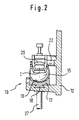
- Fig. 2
- den Sensor von Fig. 1 in einer teilgeschnittenen Vorderansicht; und
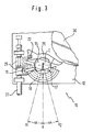
- Fig. 3
- den Sensor von Fig. 1 in zwei verschwenkten Stellungen in einer schematischen Seitenansicht.
- Fig. 1
- a sensor according to the invention in a non-pivoted position in a schematic side view;
- Fig. 2
- the sensor of Figure 1 in a partially sectioned front view. and
- Fig. 3
- the sensor of Fig. 1 in two pivoted positions in a schematic side view.
In Fig. 1 ist ein Sensor 10 für die fahrzeugsensitive Auslösung des Sperrmechanismus eines (nicht dargestellten) Sicherheitsgurtaufrollers in der Lehne eines Fahrzeugsitzes dargestellt. Dieser Sensor 10 umfaßt eine Grundplatte 12 und eine Kugelaufnahme 17, die eine Mulde 16 zur Aufnahme einer Sensorkugel 15 aufweist und mit der Grundplatte 12 über eine deutlicher in Fig. 2 zu sehende Schwalbenschwanzführung 18 verbunden ist, die zum Mittelpunkt C der Sensorkugel 15 konzentrisch ist. Die Kugelaufnahme 17 ist mit einem Fortsatz 19 versehen, an dem ein Verstellelement 25 angreift. Eine transiatorische Verstellung dieses Verstellelements 25 bewirkt über den Fortsatz 19 ein Verschwenken der Kugelaufnahme 17 in der Schwalbenschwanzführung 18 um den Mittelpunkt C der Sensorkugel 15.1 shows a
Auf der in der Mulde der Kugelaufnahme 17 angeordneten Sensorkugel 15 liegt ein Sensorhebel 20 auf, der an einem Bolzen 22 gelagert ist, der ebenfalls mit der Grundplatte 12 verbunden ist. Der Sensorhebel 20 ist dafür vorgesehen, bei Auslösung des Sensors 10 durch eine Lageänderung der Sensorkugel 15 in der Kugelaufnahme 17 verschwenkt zu werden und mit der Spitze an seinem freien Ende in die Verzahnung einer schematisch dargestellten Steuerscheibe 30 des Sicherheitsgurtaufrollers einzugreifen, wodurch diese drehfest gehalten wird und eine Sperrung des Sicherheitsgurtaufrollers fahrzeugsensitiv auslöst. Dies ist dem Fachmann auf dem Gebiet der Fahrzeuginsassen-Sicherheitssysteme gut bekannt, weshalb hier weder auf das Auslösen des Sensors noch auf den Sicherheitsgurtaufroller weiter eingegangen wird.A
In Fig. 1 ist der Sensor 10 in seiner konstruktiv vorgesehenen Betriebslage dargestellt, in welcher die Richtung der an der Senorkugel 15 angreifenden Schwerkraft mit der Achse V zusammenfällt. Ändert sich ausgehend von dieser Lage die Orientierung des Sensors 10, so nimmt die Wirkrichtung der an der Sensorkugel 15 angreifenden Schwerkraft beispielsweise die in Fig. 3 dargestellten Richtungen V1 oder V2 an. Damit gewährleistet ist, daß der Sensor 10 auch in diesen Stellungen ein Auslöseverhalten aufweist, das mit dem konstruktiv vorgesehenen übereinstimmt, wird die Kugelaufnahme 17 über den Fortsatz 19 von dem Verstellelement 25 verschwenkt. Dies ist in Fig. 3 zu sehen, wobei das Verstellelement 25 und die Kugelaufnahme 17 mit durchgezogenen Linien in der der Wirkrichtung V2 zugeordneten Stellung und mit gestrichelten Linien in der der Wirkrichtung V1 zugeordneten Stellung dargestellt sind. Aufgrund der speziellen Gestaltung der Schwalbenschwanzführung 18 ändert sich bei einem Verschwenken der Kugelaufnahme 17 die Relativstellung zwischen der Sensorkugel 15 und der Steuerscheibe 30 nicht. Somit bleibt neben dem Auslöseverhalten des Sensors 10 auch der Abstand zwischen dem freien Ende des Sensorhebels 20 und dem Umfang der Steuerscheibe 30 unverändert. Da nur die Kugelaufnahme 17 verschwenkt wird, ist der für den Sensor 10 notwendige Einbauraum sehr klein.In Fig. 1 the
Das Verschwenken des Kugelaufnahme 17 aus der in Fig. 1 dargestellten Neutrallage in die in Fig. 3 dargestellten verschwenkten Stellungen wird von einer Translationsbewegung des Verstellelements 25 bewirkt, die von einer Verstellvorrichtung 27 hervorgerufen wird, deren sensorseitiges Ende mit der Sensorgrundplatte 12 verbunden ist. Diese Verstellvorrichtung 27 kann ein Zug/Schubglied wie ein Bowdenzug sein, mit welchem das Verstellelement 25 fest verbunden ist. Eine Verstellung des Zug/Schubgliedes 27 entlang seiner Längsrichtung bewirkt eine entsprechende Translationsbewegung des Verstellelements 25, die über den Fortsatz 19 zu einem Verschwenken der Kugelaufnahme 17 um den Mittelpunkt C der Sensorkugel 15 führt.The pivoting of the
Die Verstellvorrichtung 27 kann auch ein drehbares Kraftübertragungsglied sein, dessen Drehbewegung an dem sensorseitigen Ende der Verstellvorrichtung 27 in eine Translationsbewegung des Verstellelementes 25 umgesetzt wird, z.B. mittels eines Gewindes, das am sensorseitigen Ende des drehbaren Kraftübertragungsgliedes 27 ausgebildet ist und auf welches das Verstellelement 25, das mit einem komplementären Gewinde versehen ist, aufgesetzt ist. Somit wirkt eine Drehung des drehbaren Kraftübertragungsgliedes 27 in der gleichen Weise wie eine translatorische Verschiebung des Zug/Schubgliedes.The adjusting
Das zu dem sensorseitigen Ende der Verstellvorrichtung 27 entgegengesetzte (nicht dargestellte) Ende der Verstellvorrichtung 27 steht mit einer geeigneten Einrichtung wie einem (nicht dargestellten) Getriebe in Verbindung, das ein Verschwenken der Lehne des Fahrzeugsitzes abgreift und ein solches Einwirken auf das Verstellelelment 25 gewährleistet, daß die Orientierung des Sensors 10 unabhängig von der Lehnenneigung beibehalten wird.The end of the adjusting device 27 (not shown) opposite the sensor-side end of the adjusting
Claims (6)
Applications Claiming Priority (2)
| Application Number | Priority Date | Filing Date | Title |
|---|---|---|---|
| DE19500722 | 1995-01-12 | ||
| DE19500722A DE19500722A1 (en) | 1995-01-12 | 1995-01-12 | Sensor for a seat belt retractor |
Publications (3)
| Publication Number | Publication Date |
|---|---|
| EP0721868A1 true EP0721868A1 (en) | 1996-07-17 |
| EP0721868B1 EP0721868B1 (en) | 1999-05-06 |
| EP0721868B2 EP0721868B2 (en) | 2002-05-02 |
Family
ID=7751343
Family Applications (1)
| Application Number | Title | Priority Date | Filing Date |
|---|---|---|---|
| EP95119927A Expired - Lifetime EP0721868B2 (en) | 1995-01-12 | 1995-12-18 | Sensor for safety belt retractor |
Country Status (4)
| Country | Link |
|---|---|
| US (1) | US5622383A (en) |
| EP (1) | EP0721868B2 (en) |
| DE (2) | DE19500722A1 (en) |
| ES (1) | ES2093584T3 (en) |
Cited By (4)
| Publication number | Priority date | Publication date | Assignee | Title |
|---|---|---|---|---|
| EP0858934A1 (en) * | 1997-02-18 | 1998-08-19 | Takata Corporation | Seat belt device |
| EP0832796A3 (en) * | 1996-09-26 | 1999-05-19 | Trw Vehicle Safety Systems Inc. | Vehicle seat with belt locking mechanism controlled by seat back orientation |
| DE102014208570A1 (en) | 2014-05-07 | 2015-11-12 | Autoliv Development Ab | Belt retractor for a safety belt device for a motor vehicle |
| WO2015185486A1 (en) * | 2014-06-03 | 2015-12-10 | Autoliv Development Ab | Belt retractor for a seat belt device for a motor vehicle |
Families Citing this family (16)
| Publication number | Priority date | Publication date | Assignee | Title |
|---|---|---|---|---|
| DE19532781C2 (en) * | 1995-09-06 | 1998-01-29 | Autoliv Dev | Seat belt retractor with two vehicle-sensitive sensors with different response thresholds |
| DE19717689B4 (en) * | 1997-04-28 | 2006-09-07 | C. Rob. Hammerstein Gmbh & Co. Kg | Gurtintegralsitz a motor vehicle with a retractor for the safety belt and a controlling this sensor |
| JP3455426B2 (en) | 1998-06-09 | 2003-10-14 | 株式会社東海理化電機製作所 | Acceleration sensor |
| GB2349119B (en) * | 1999-04-21 | 2001-05-30 | Breed Automotive Tech | A sensor for a seat belt retractor |
| DE20006314U1 (en) | 2000-04-06 | 2000-08-17 | Trw Repa Gmbh | Inertia sensor |
| US20060243846A1 (en) * | 2005-04-29 | 2006-11-02 | Autoliv Asp, Inc. | Vehicle sensitive seat belt retractor control with suppressed Z-axis sensitivity |
| KR100751773B1 (en) * | 2007-01-24 | 2007-08-23 | 주식회사 삼송 | Seat belt retractor |
| US20080217458A1 (en) * | 2007-03-05 | 2008-09-11 | Autoliv Asp, Inc. | Hybrid vehicle sensitive seat belt retractor inertial locking system |
| US7628349B2 (en) * | 2007-03-06 | 2009-12-08 | Autoliv Asp, Inc. | Inertia actuator for seat belt retractor |
| US7568649B2 (en) * | 2007-03-23 | 2009-08-04 | Autoliv Asp, Inc. | Vehicle sensitive seat belt retractor control with suppressed Z-axis sensitivity |
| DE102009052495B8 (en) | 2009-11-11 | 2012-03-22 | Autoliv Development Ab | Self-locking belt retractor |
| TWM409985U (en) * | 2010-10-27 | 2011-08-21 | Guo-Hao Li | Snap device for safety belt |
| DE102011103113A1 (en) * | 2011-05-25 | 2012-11-29 | Trw Automotive Gmbh | Assembly for a belt retractor |
| US9434347B2 (en) | 2012-12-10 | 2016-09-06 | Autoliv Asp, Inc. | Low noise, debris tolerant retractor inertial sensor |
| DE102014111923B4 (en) * | 2014-08-20 | 2017-03-30 | Volkswagen Aktiengesellschaft | Armrest with crash protection |
| US11794688B2 (en) * | 2021-09-14 | 2023-10-24 | Autoliv Asp, Inc. | Vehicle sensitive seat belt retractor control with suppressed Z-axis sensitivity |
Citations (3)
| Publication number | Priority date | Publication date | Assignee | Title |
|---|---|---|---|---|
| FR2258662A1 (en) * | 1974-01-22 | 1975-08-18 | Foehl Artur | |
| US4556177A (en) * | 1982-09-24 | 1985-12-03 | Nippon Soken, Inc. | Lock-type seat belt retractor of automobile |
| EP0315955A2 (en) * | 1987-11-10 | 1989-05-17 | Autoliv Development Aktiebolag | Acceleration sensor for vehicle-sensitive systems |
Family Cites Families (9)
| Publication number | Priority date | Publication date | Assignee | Title |
|---|---|---|---|---|
| DE2513023A1 (en) * | 1975-03-25 | 1976-10-07 | Daimler Benz Ag | SENSOR RELEASED BY DELAY FORCE |
| DE2658747C2 (en) * | 1976-12-24 | 1986-01-30 | Autoflug Gmbh, 2084 Rellingen | Seat belt system |
| FR2377085A1 (en) * | 1977-01-10 | 1978-08-04 | Fligue Wladimir | Polarised relay system with inertia switch - has ball on conical seating restrained by spring and releasing latch |
| FR2565404B1 (en) * | 1984-06-05 | 1988-03-18 | Seb Sa | MULTIDIRECTIONAL SWITCH CONTROLLED BY A BALL |
| JPH0256059U (en) * | 1988-10-17 | 1990-04-23 | ||
| JP2576496Y2 (en) * | 1990-03-23 | 1998-07-09 | アイシン精機株式会社 | Acceleration sensor |
| US5136127A (en) * | 1991-09-16 | 1992-08-04 | Honeywell Inc. | Tilt actuated switch |
| US5358276A (en) * | 1993-10-25 | 1994-10-25 | Trw Vehicle Safety Systems Inc. | Seat belt webbing clamp assembly |
| US5495994A (en) * | 1994-09-07 | 1996-03-05 | Trw Vehicle Safety Systems Inc. | Inertia sensitive seat belt retractor |
-
1995
- 1995-01-12 DE DE19500722A patent/DE19500722A1/en not_active Withdrawn
- 1995-12-18 EP EP95119927A patent/EP0721868B2/en not_active Expired - Lifetime
- 1995-12-18 ES ES95119927T patent/ES2093584T3/en not_active Expired - Lifetime
- 1995-12-18 DE DE59505841T patent/DE59505841D1/en not_active Expired - Fee Related
-
1996
- 1996-01-05 US US08/583,316 patent/US5622383A/en not_active Expired - Fee Related
Patent Citations (3)
| Publication number | Priority date | Publication date | Assignee | Title |
|---|---|---|---|---|
| FR2258662A1 (en) * | 1974-01-22 | 1975-08-18 | Foehl Artur | |
| US4556177A (en) * | 1982-09-24 | 1985-12-03 | Nippon Soken, Inc. | Lock-type seat belt retractor of automobile |
| EP0315955A2 (en) * | 1987-11-10 | 1989-05-17 | Autoliv Development Aktiebolag | Acceleration sensor for vehicle-sensitive systems |
Cited By (8)
| Publication number | Priority date | Publication date | Assignee | Title |
|---|---|---|---|---|
| EP0832796A3 (en) * | 1996-09-26 | 1999-05-19 | Trw Vehicle Safety Systems Inc. | Vehicle seat with belt locking mechanism controlled by seat back orientation |
| EP0858934A1 (en) * | 1997-02-18 | 1998-08-19 | Takata Corporation | Seat belt device |
| US6015164A (en) * | 1997-02-18 | 2000-01-18 | Takata Corporation | Seat belt device |
| DE102014208570A1 (en) | 2014-05-07 | 2015-11-12 | Autoliv Development Ab | Belt retractor for a safety belt device for a motor vehicle |
| DE102014208570B4 (en) | 2014-05-07 | 2018-08-23 | Autoliv Development Ab | Belt retractor for a safety belt device for a motor vehicle |
| WO2015185486A1 (en) * | 2014-06-03 | 2015-12-10 | Autoliv Development Ab | Belt retractor for a seat belt device for a motor vehicle |
| DE102014210396A1 (en) * | 2014-06-03 | 2016-01-07 | Autoliv Development Ab | Belt retractor for a safety belt device for a motor vehicle |
| DE102014210396B4 (en) * | 2014-06-03 | 2021-05-27 | Autoliv Development Ab | Belt retractor for a seat belt device for a motor vehicle |
Also Published As
| Publication number | Publication date |
|---|---|
| DE19500722A1 (en) | 1996-07-18 |
| US5622383A (en) | 1997-04-22 |
| EP0721868B1 (en) | 1999-05-06 |
| ES2093584T3 (en) | 1999-08-16 |
| EP0721868B2 (en) | 2002-05-02 |
| DE59505841D1 (en) | 1999-06-10 |
| ES2093584T1 (en) | 1997-01-01 |
Similar Documents
| Publication | Publication Date | Title |
|---|---|---|
| EP0721868A1 (en) | Sensor for safety belt retractor | |
| DE19738492A1 (en) | Road vehicle door closure | |
| WO2004108487A1 (en) | Belt buckling device for a vehicle seat | |
| EP0351551B1 (en) | Safety belt arrangement for a motor vehicle seat with tilt adjustment | |
| DE19939340A1 (en) | Inertial locking assembly for a seat guide | |
| DE3414316C2 (en) | ||
| EP0932521B1 (en) | Head rest for a vehicle seat | |
| DE19858416A1 (en) | Collision protection for vehicle door lock has an inertial mass displaced by the door opening mechanism and which blocks the lock when displaced by impact forces | |
| DE4218792A1 (en) | Three-point seat belt system for motor vehicles | |
| DE19532781A1 (en) | Safety belt winder with two sensors | |
| EP0285793B1 (en) | Seat contact switch | |
| DE2618844A1 (en) | SAFETY BELT ROLLER WITH WEAR DEVICE | |
| DE10009291A1 (en) | Armrest with integrated stowage compartment for seat of motor vehicle has hinged cover closing off stowage compartment and fixed in at least one open position by locking unit activated by positive or negative acceleration of vehicle | |
| DE3611004A1 (en) | Locking device for the belt of an automatic belt retraction device which is assigned to a reclining seat part a motor vehicle | |
| EP0377861B1 (en) | Seat belt clamping device for an automotive vehicle | |
| DE3229304A1 (en) | Tensioner for a safety-belt system for motor vehicles | |
| DE19930363C1 (en) | Ratchet mechanism blocking device for automobile seat backrest adjustment has inertia sensor triggering pyrotechnic release of blocking bolt locating in blocking opening of counter element | |
| DE10201092A1 (en) | Safety device for motor vehicle seat benches has inertia body adjusted in position by acceleration or deceleration forces, and acting with locking element to lock into securing rail under seat | |
| EP0861170B1 (en) | Belt fitting for a safety belt | |
| DE10025676A1 (en) | Vehicle seat has frame mounted on levers, two of which can pivot on connecting tube, toothed wheel mounted on this being locked in position by pivoting latches and mounting for seat belt lock connected to latches | |
| DE102005028174B4 (en) | Belt retractor with force limiting device | |
| DE60017970T2 (en) | Seat belt retractor | |
| DE20216345U1 (en) | Crash locking mechanism for a vehicle seat adjustment mechanism, prevents movement of the seat in a crash situation by means of an energy storing element actuated on impact | |
| DE19528387C2 (en) | Seat belt retractor with inclination compensation for the vehicle-sensitive sensor | |
| DE2408458A1 (en) | EMERGENCY LOCK RETRACTOR |
Legal Events
| Date | Code | Title | Description |
|---|---|---|---|
| PUAI | Public reference made under article 153(3) epc to a published international application that has entered the european phase |
Free format text: ORIGINAL CODE: 0009012 |
|
| AK | Designated contracting states |
Kind code of ref document: A1 Designated state(s): DE ES FR GB IT SE |
|
| GBC | Gb: translation of claims filed (gb section 78(7)/1977) | ||
| ITCL | It: translation for ep claims filed |
Representative=s name: DR. ING. A. RACHELI & C. |
|
| 17P | Request for examination filed |
Effective date: 19960812 |
|
| EL | Fr: translation of claims filed | ||
| REG | Reference to a national code |
Ref country code: ES Ref legal event code: BA2A Ref document number: 2093584 Country of ref document: ES Kind code of ref document: T1 |
|
| 17Q | First examination report despatched |
Effective date: 19980310 |
|
| RAP1 | Party data changed (applicant data changed or rights of an application transferred) |
Owner name: TRW OCCUPANT RESTRAINT SYSTEMS GMBH & CO. KG |
|
| GRAG | Despatch of communication of intention to grant |
Free format text: ORIGINAL CODE: EPIDOS AGRA |
|
| GRAG | Despatch of communication of intention to grant |
Free format text: ORIGINAL CODE: EPIDOS AGRA |
|
| GRAH | Despatch of communication of intention to grant a patent |
Free format text: ORIGINAL CODE: EPIDOS IGRA |
|
| GRAH | Despatch of communication of intention to grant a patent |
Free format text: ORIGINAL CODE: EPIDOS IGRA |
|
| GRAA | (expected) grant |
Free format text: ORIGINAL CODE: 0009210 |
|
| AK | Designated contracting states |
Kind code of ref document: B1 Designated state(s): DE ES FR GB IT SE |
|
| PG25 | Lapsed in a contracting state [announced via postgrant information from national office to epo] |
Ref country code: SE Free format text: THE PATENT HAS BEEN ANNULLED BY A DECISION OF A NATIONAL AUTHORITY Effective date: 19990506 Ref country code: FR Free format text: LAPSE BECAUSE OF NON-PAYMENT OF DUE FEES Effective date: 19990506 |
|
| REF | Corresponds to: |
Ref document number: 59505841 Country of ref document: DE Date of ref document: 19990610 |
|
| ET | Fr: translation filed | ||
| GBT | Gb: translation of ep patent filed (gb section 77(6)(a)/1977) |
Effective date: 19990622 |
|
| REG | Reference to a national code |
Ref country code: ES Ref legal event code: FG2A Ref document number: 2093584 Country of ref document: ES Kind code of ref document: T3 |
|
| PLAV | Examination of admissibility of opposition |
Free format text: ORIGINAL CODE: EPIDOS OPEX |
|
| PLBQ | Unpublished change to opponent data |
Free format text: ORIGINAL CODE: EPIDOS OPPO |
|
| PLBI | Opposition filed |
Free format text: ORIGINAL CODE: 0009260 |
|
| PLAV | Examination of admissibility of opposition |
Free format text: ORIGINAL CODE: EPIDOS OPEX |
|
| PLBF | Reply of patent proprietor to notice(s) of opposition |
Free format text: ORIGINAL CODE: EPIDOS OBSO |
|
| 26 | Opposition filed |
Opponent name: AUTOLIV DEVELOPMENT AB Effective date: 20000204 |
|
| PLBF | Reply of patent proprietor to notice(s) of opposition |
Free format text: ORIGINAL CODE: EPIDOS OBSO |
|
| PLBF | Reply of patent proprietor to notice(s) of opposition |
Free format text: ORIGINAL CODE: EPIDOS OBSO |
|
| PGFP | Annual fee paid to national office [announced via postgrant information from national office to epo] |
Ref country code: GB Payment date: 20001107 Year of fee payment: 6 |
|
| PGFP | Annual fee paid to national office [announced via postgrant information from national office to epo] |
Ref country code: FR Payment date: 20001204 Year of fee payment: 6 |
|
| PGFP | Annual fee paid to national office [announced via postgrant information from national office to epo] |
Ref country code: ES Payment date: 20001219 Year of fee payment: 6 |
|
| PLAW | Interlocutory decision in opposition |
Free format text: ORIGINAL CODE: EPIDOS IDOP |
|
| PLAW | Interlocutory decision in opposition |
Free format text: ORIGINAL CODE: EPIDOS IDOP |
|
| PG25 | Lapsed in a contracting state [announced via postgrant information from national office to epo] |
Ref country code: GB Free format text: LAPSE BECAUSE OF NON-PAYMENT OF DUE FEES Effective date: 20011218 |
|
| REG | Reference to a national code |
Ref country code: GB Ref legal event code: IF02 |
|
| PUAH | Patent maintained in amended form |
Free format text: ORIGINAL CODE: 0009272 |
|
| STAA | Information on the status of an ep patent application or granted ep patent |
Free format text: STATUS: PATENT MAINTAINED AS AMENDED |
|
| 27A | Patent maintained in amended form |
Effective date: 20020502 |
|
| AK | Designated contracting states |
Kind code of ref document: B2 Designated state(s): DE ES FR GB IT SE |
|
| GBPC | Gb: european patent ceased through non-payment of renewal fee |
Effective date: 20011218 |
|
| PG25 | Lapsed in a contracting state [announced via postgrant information from national office to epo] |
Ref country code: ES Free format text: LAPSE BECAUSE OF FAILURE TO SUBMIT A TRANSLATION OF THE DESCRIPTION OR TO PAY THE FEE WITHIN THE PRESCRIBED TIME-LIMIT Effective date: 20020813 |
|
| REG | Reference to a national code |
Ref country code: FR Ref legal event code: ST |
|
| EN | Fr: translation not filed | ||
| PG25 | Lapsed in a contracting state [announced via postgrant information from national office to epo] |
Ref country code: IT Free format text: LAPSE BECAUSE OF NON-PAYMENT OF DUE FEES Effective date: 20051218 |
|
| PGFP | Annual fee paid to national office [announced via postgrant information from national office to epo] |
Ref country code: DE Payment date: 20061229 Year of fee payment: 12 |
|
| PG25 | Lapsed in a contracting state [announced via postgrant information from national office to epo] |
Ref country code: DE Free format text: LAPSE BECAUSE OF NON-PAYMENT OF DUE FEES Effective date: 20080701 |