EP0721859A1 - Spectacles dolder in particular for installation in motor vehicles - Google Patents
Spectacles dolder in particular for installation in motor vehicles Download PDFInfo
- Publication number
- EP0721859A1 EP0721859A1 EP96103367A EP96103367A EP0721859A1 EP 0721859 A1 EP0721859 A1 EP 0721859A1 EP 96103367 A EP96103367 A EP 96103367A EP 96103367 A EP96103367 A EP 96103367A EP 0721859 A1 EP0721859 A1 EP 0721859A1
- Authority
- EP
- European Patent Office
- Prior art keywords
- glasses
- protective housing
- holder
- spectacle
- holder according
- Prior art date
- Legal status (The legal status is an assumption and is not a legal conclusion. Google has not performed a legal analysis and makes no representation as to the accuracy of the status listed.)
- Granted
Links
Images


Classifications
-
- B—PERFORMING OPERATIONS; TRANSPORTING
- B60—VEHICLES IN GENERAL
- B60R—VEHICLES, VEHICLE FITTINGS, OR VEHICLE PARTS, NOT OTHERWISE PROVIDED FOR
- B60R7/00—Stowing or holding appliances inside vehicle primarily intended for personal property smaller than suit-cases, e.g. travelling articles, or maps
- B60R7/08—Disposition of racks, clips, holders, containers or the like for supporting specific articles
- B60R7/082—Disposition of racks, clips, holders, containers or the like for supporting specific articles for supporting spectacles
-
- B—PERFORMING OPERATIONS; TRANSPORTING
- B60—VEHICLES IN GENERAL
- B60R—VEHICLES, VEHICLE FITTINGS, OR VEHICLE PARTS, NOT OTHERWISE PROVIDED FOR
- B60R1/00—Optical viewing arrangements; Real-time viewing arrangements for drivers or passengers using optical image capturing systems, e.g. cameras or video systems specially adapted for use in or on vehicles
- B60R1/12—Mirror assemblies combined with other articles, e.g. clocks
- B60R2001/1292—Mirror assemblies combined with other articles, e.g. clocks with holding means for personal articles
-
- Y—GENERAL TAGGING OF NEW TECHNOLOGICAL DEVELOPMENTS; GENERAL TAGGING OF CROSS-SECTIONAL TECHNOLOGIES SPANNING OVER SEVERAL SECTIONS OF THE IPC; TECHNICAL SUBJECTS COVERED BY FORMER USPC CROSS-REFERENCE ART COLLECTIONS [XRACs] AND DIGESTS
- Y10—TECHNICAL SUBJECTS COVERED BY FORMER USPC
- Y10S—TECHNICAL SUBJECTS COVERED BY FORMER USPC CROSS-REFERENCE ART COLLECTIONS [XRACs] AND DIGESTS
- Y10S248/00—Supports
- Y10S248/902—Eyeglasses holder
Abstract
Description
Die vorliegende Erfindung betrifft eine Brillenhalterung, insbesondere für den Einbau in Kraftfahrzeugen (Kfzg.).The present invention relates to a glasses holder, in particular for installation in motor vehicles (Kfzg.).
Der Gebrauch von Seh- und Sonnenbrillen in Kfzg. ist weit verbreitet. Insbesondere für den Fahrer muss die Brille bei plötzlich auftretender Blendung oder Abdunklung, beispielsweise beim Durchfahren von Tunnels, oft kurzfristig während der Fahrt handhabbar sein, sodass dazu lediglich eine Hand zur Verfügung steht. Es ist daher erforderlich, dass die Brille im Kfzg. so aufbewahrt werden kann, dass sie vom Fahrer einhändig in die Aufbewahrungsvorrichtung eingelegt bzw. aus dieser entnommen werden kann.The use of vision and sunglasses in Kfzg. is widespread. In particular for the driver, the glasses often have to be able to be handled briefly while driving in the event of sudden glare or darkening, for example when driving through tunnels, so that only one hand is available for this purpose. It is therefore necessary that the glasses in the Kfzg. can be stored in such a way that the driver can insert or remove it from the storage device with one hand.
Dabei sollen auch die Brillenbügel einhändig auf- und zugeklappt werden können, ohne dass dazu eine den Fahrer ablenkende Aufmerksamkeit erforderlich ist.The glasses should also be able to be opened and closed with one hand, without the need to distract the driver.
Einerseits soll die Brille problemlos und leichtgängig in die Aufbewahrungsvorrichtung eingelegt und aus dieser entnommen werden können, andererseits muss die Brille so gut in der Aufbewahrungsvorrichtung plaziert und festgehalten werden, dass auch schwergängige Brillenbügel auf- und zugeklappt werden können, ohne dass die Brille dabei aus der Aufbewahrungsvorrichtung gerissen oder deformiert werden kann.On the one hand, the glasses should be able to be inserted and removed from the storage device easily and smoothly, on the other hand, the glasses must be placed and held so well in the storage device that even stiff eyeglass temples can be opened and closed without the glasses coming out of the Storage device can be torn or deformed.
Im aufbewahrten Zustand soll die Brille vor Staub, Verschmutzung und Verkratzen geschützt sein. Ebenso ist eine Abschirmung gegen Sonneneinstrahlung erwünscht. Damit die Bedienung durch den Fahrer während der Fahrt möglich ist, muss die Vorrichtung einerseits im Kfzg. so anbringbar und bedienbar sein, dass der Blick des Fahrers dazu nicht von der Strasse weichen muss. Andererseits darf die Sicht des Fahrers durch die Vorrichtung nicht beinträchtigt werden. Die Verwendung der Vorrichtung in zahlreichen verschiedenen Kfzg.-Modellen erfordert ferner eine möglichst universelle Einbauart, die in den einzelnen Kfzg.-Modellen nur minimale und kostengünstige Anpassungen notwendig macht.When stored, the glasses should be protected from dust, dirt and scratches. Shielding against solar radiation is also desirable. The device must be operated so that it can be operated by the driver while driving on the one hand in the Kfzg. can be attached and operated in such a way that the driver's eyes do not have to leave the street. On the other hand, the driver's view must not be impaired by the device. The use of the device in numerous different Kfzg. Models also requires the most universal possible type of installation, which in the individual Kfz. Models only requires minimal and inexpensive adjustments.
Brillen sind in unzähligen Ausführungen auf dem Markt erhältlich. Form, Höhe, Breite und Dicke sowie die Nasenausnehmung und die Anordnung der Bügel variieren in einem grossen Streubereich. Es gibt auch zahlreiche Brillenmodelle in sehr empfindlichen Ausführungen, die sich bei Anwendung von Druck leicht deformieren lassen.Glasses are available in countless versions on the market. Shape, height, width and thickness as well as the nose recess and the arrangement of the temples vary in a large spreading area. There are also numerous glasses models in very sensitive designs that can be easily deformed when pressure is applied.
Aus der US-A 4,695,026 ist eine Brillenhalterung mit einer Aufnahme zum Abstützen einer Schmalseite einer Brille sowie einer Klammer zum Halten der Brille auf einer gegenüberliegenden Schmalseite bekannt. Die Aufnahme ist eine Art Steg, der beispielsweise von einem Armaturenbrett eines Kraftfahrzeugs abstehend anbringbar ist und der einen Nasenbügel einer eingelegten Brille untergreift. Die Klammer ist federbelastet, greift an einer Schalseite der Brille an und drückt sie gegen die Aufnahme. Ist keine Brille in die bekannte Brillenhalterung eingesetzt, so liegt die Klammer auf der Aufnahme auf. Dies hat den Nachteil, daß die Klammer beim Einsetzen der Brille nicht mit dieser von der Aufnahme weggedrückt werden kann, sondern von Hand weggedrückt werden muß, damit die Brille in die Brillenhalterung eingesetzt werden kann. Das Einsetzen der Brille in die bekannte Brillenhalterung erfordert zumindest einiges an Übung und Geschicklichkeit, wenn es mit einer Hand erfolgen soll und beansprucht die Aufmerksamkeit des Fahrers, so daß er sich nicht auf die Straße konzentrieren kann.From US-A 4,695,026 an eyeglass holder with a receptacle for supporting a narrow side of a pair of glasses and a clip for holding the pair of glasses on an opposite narrow side is known. The receptacle is a type of web that can be attached, for example, projecting from a dashboard of a motor vehicle and that engages under a nose piece of inserted glasses. The clip is spring-loaded, engages on a scarf side of the glasses and presses it against the holder. If no glasses are inserted into the known glasses holder, the clip rests on the holder. This has the disadvantage that the clip cannot be pushed away from the receptacle when the glasses are inserted, but must be pushed away by hand so that the glasses can be inserted into the glasses holder. The insertion of the glasses into the known glasses holder requires at least some practice and skill if it is to be done with one hand and requires the driver's attention so that he can not concentrate on the road.
Der Erfindung liegt die Aufgabe zugrunde, eine Halterung zur Aufbewahrung und Ablage von verschiedenartigen Brillenmodelle, insbesondere für Kraftfahrzeuge zu schaffen, in welcher die Brillen geschützt sind und einhändig abgelegt bzw. entnommen werden können.The invention has for its object to provide a holder for storing and storing various types of glasses, especially for motor vehicles, in which the glasses are protected and can be stored or removed with one hand.
Die Lösung dieser Aufgabe wird mit den Merkmalen des Anspruchs 1 erreicht.This object is achieved with the features of
Die erfindungsgemäße Brillenhaltetung besteht aus einem Träger und einer an diesem angeordneten Aufnahme zum Abstützen einer Schmalseite einer Brille, sowie einer federbelasteten Klammer, die die Brille übergreift und gegen die Aufnahme drückt, so daß die Brille gehalten wird. Dabei weist die Klammer einen Abstand von der Aufnahme auf, wenn keine Brille eingesetzt ist. Dadurch kann die Brille einhändig aus der Brillenhalterung entnommen bzw. in diese eingesetzt und die Brillenbügel in den Brillen auf- und zugeklappt werden. Damit eignet sich die Brillenhalterung insbesondere zum Einbau in Kraftfahrzeugen, da aus Sicherheitsgründen eine einhändige Entnahme und Ablage erforderlich ist.The glasses holder according to the invention consists of a carrier and a receptacle arranged thereon for supporting a narrow side of glasses, and a spring-loaded clamp which engages over the glasses and presses against the holder, so that the glasses are held. The clip is at a distance from the receptacle when no glasses are inserted. As a result, the glasses can be removed from or inserted into the glasses holder with one hand and the glasses arms in the glasses can be opened and closed. The eyeglass holder is therefore particularly suitable for installation in motor vehicles, since for safety reasons a one-handed removal and storage is required.
Die Brillenhalterung ist als einheitliche Baugruppe ausgebildet und kann in verschiedenartigen Schutzgehäusen eingebaut - und mittels einer Ausfahrmechanik von einer inneren Raststellung, in welcher die Brillenhalterung im wesentlichen im Schutzgehäuse eingeschlossen ist, in eine äußere Raststellung, in welcher die Brille bequem aus der Brillenhalterung entnommen bzw. in diese eingesetzt werden kann, bewegt werden.The glasses holder is designed as a unitary assembly and can be installed in various types of protective housings - and by means of an extension mechanism from an inner locking position, in which the glasses holder is essentially enclosed in the protective housing, to an outer locking position, in which the glasses are easily removed from the glasses holder or can be used in these can be moved.
Weitere Merkmale und Vorteile der Erfindung ergeben sich aus den Unteransprüchen bzw. aus der Beschreibung von Ausführungsbeispielen.Further features and advantages of the invention result from the subclaims or from the description of exemplary embodiments.
Ausführungsbeispiele der Erfindung werden nachstehend unter Bezugnahme auf die beigefügten Zeichnungen näher erläutert.
- Fig. 1 und 2
- zeigen eine schematische Frontansicht bzw. einen Querschnitt einer ersten Ausführungsform einer erfindungsgemäßen Brillenhalterung
- Fig. 3 und 4
- zeigen in schematischer Frontansicht bzw. im Querschnitt eine weitere Ausführungsform der Brillenhalterung.
- Fig. 5
- zeigt eine Variante der Brillenhalterung mit zwei eingesetzten Schutzelementen in Frontansicht.
- Fig. 6
- zeigt die Brillenhalterung gemäß Figur 5 im Querschnitt.
- Fig. 7
- zeigt in Seitenansicht eine erste Variante eines Schutzgehäuses mit eingebauter Brillenhalterung in der äusseren Raststellung.
- Fig. 8
- zeigt in Seitenansicht eine zweite Variante eines Schutzgehäuses mit eingebauter Brillenhalterung in der äusseren Raststellung.
- Fig. 9
- zeigt in Seitenansicht eine dritte Variante eines Schutzgehäuses mit eingebauter Brillenhalterung in der äusseren Raststellung.
- Fig. 10
- zeigt in Seitenansicht eine vierte Variante eines Schutzgehäuses mit eingebauter Brillenhalterung in der äusseren Raststellung.
- Fig. 11
- zeigt in Seitenansicht eine fünfte Variante eines Schutzgehäuses mit eingebauter Brillenhalterung in der inneren und äusseren Raststellung.
- Fig. 12
- zeigt im Querschnitt ein an einem Innenrückspiegel angeordnetes Schutzgehäuse mit der Brillenhalterung in der inneren und äusseren Raststellung.
- Fig. 13
- zeigt im Querschnitt in schematischer Ansicht eine weitere Ausführungsform eines an einem Innenrückspiegel angeordneten Schutzgehäuses mit der Brillenhalterung in der inneren und äusseren Raststellung.
- Fig. 14
- zeigt im Querschnitt in schematischer Ansicht die Ausführungsform gemäss Fig. 13 mit einer Vorrichtung zum Oeffnen und Schliessen der Bügel einer in die Brillenhalterung eingesetzten Brille in der inneren und äusseren Raststellung.
- Fig. 15
- zeigt in teilweiser Frontansicht schematisch einen Ausschnitt der Vorrichtung gemäss Fig. 14 ohne eingesetzte Brille.
- Fig. 16
- zeigt in perspektivischer Ansicht schematisch die Ausführungsform gem. Fig. 13 bis 15.
- Fig. 17
- zeigt im Längsschnitt eine schematische Detailkonstruktion der Vorrichtung zum Oeffnen und Schliessen der Brillenbügel in der ein- bzw. ausgeklappten Stellung.
- Fig. 18
- zeigt im Querschnitt eine schematische Detailkonstruktion der Vorrichtung zum Oeffnen und Schliessen der Brillenbügel in der ein- bzw. ausgeklappten Stellung.
- 1 and 2
- show a schematic front view or a cross section of a first embodiment of an eyeglass holder according to the invention
- 3 and 4
- show in a schematic front view or in cross section a further embodiment of the glasses holder.
- Fig. 5
- shows a variant of the glasses holder with two protective elements used in front view.
- Fig. 6
- shows the glasses holder according to Figure 5 in cross section.
- Fig. 7
- shows a side view of a first variant of a protective housing with built-in glasses holder in the outer latching position.
- Fig. 8
- shows a side view of a second variant of a protective housing with built-in glasses holder in the outer latching position.
- Fig. 9
- shows a side view of a third variant of a protective housing with built-in glasses holder in the outer click position.
- Fig. 10
- shows a side view of a fourth variant of a protective housing with built-in glasses holder in the outer click position.
- Fig. 11
- shows a side view of a fifth variant of a protective housing with built-in glasses holder in the inner and outer locking position.
- Fig. 12
- shows in cross section a protective housing arranged on an interior rear-view mirror with the glasses holder in the inner and outer locking position.
- Fig. 13
- shows in cross section in a schematic view a further embodiment of a protective housing arranged on an interior rear-view mirror with the glasses holder in the inner and outer locking position.
- Fig. 14
- shows in cross section in a schematic view the embodiment according to FIG. 13 with a device for opening and closing the temples of a pair of glasses inserted into the glasses holder in the inner and outer locking position.
- Fig. 15
- 14 shows a partial front view schematically of a detail of the device according to FIG. 14 without glasses inserted.
- Fig. 16
- shows a schematic view of the embodiment according to perspective. 13 to 15.
- Fig. 17
- shows in longitudinal section a schematic detail construction of the device for opening and closing the temple in the folded or unfolded position.
- Fig. 18
- shows in cross section a schematic detailed construction of the device for opening and closing the temple in the folded or unfolded position.
In den Fig. 1 und 2 wird eine weitere Ausführungsform einer Brillenhalterung gezeigt, bei welcher die Brille direkt von vorne eingesetzt bzw. entnommen werden kann.1 and 2 show a further embodiment of a spectacle holder in which the spectacles can be inserted or removed directly from the front.
Der Träger 200 hat einen L-förmigen Querschnitt mit einer Rückwand 210 und einer Bodenwand 211. Auf der Bodenwand 211 sind zwei U-förmige Aufnahmen 220 angeordnet, in welche die unteren Randsegmente 225, 226 der Brille 224 eingesetzt werden.The
Die Klammer 240 ist in der Mitte der Brillenhalterung angeordnet und in einer Führung 245 der Rückwand 210, gegen die Kraft der Feder 250 vertikal verschieblich.The
Nachdem die Brille 224 in die Aufnahmen 220 eingesetzt worden ist, kann die Brille mit den Aufnahmen 220 als "Drehpunkt" gegen den Einlauf 240a der Klammer 240 geschwenkt werden. Dabei kann die Klammer 240 gegen die Kraft der Feder 250 nach oben weichen, bis die Nase 240b hinter der Brille 224 einrastet und diese in der Brillenhalterung verriegelt. Zur Entnahme kann die Brille 224 nach vorne gekippt werden. Dadurch wird die Nase 240b nach oben ausgelenkt und die Brille 224 freigegeben.After the
Zum Anpassen der Brillenhalterung an verschiedene Brillengrössen kann der Abstand zwischen den Aufnahmen 220 und der Klammer 240 über die Verstellschraube 260 manuell verstellt werden.In order to adapt the glasses holder to different sizes of glasses, the distance between the
Alternativ könnte bei dieser Ausführungsform anstelle der beiden U-förmigen Aufnahmen 220 eine, vorzugsweise an der Rückwand 210 angeordnete Zentriernase 270 dienen, welche die Brille 224 nach unten abstützt und gleichzeitig seitlich zentriert.Alternatively, in this embodiment, instead of the two
Figuren 3 und 4 zeigen eine analoge Brillenhalterung wie Figuren 1 und 2, wobei bei dieser Ausführungsform die Aufnahme 320 am oberen Rand der Rückwand 310 angeordnet ist, während die beweglichen Klammern 340 an der Bodenwand 311 über Federn 350 abgestützt sind.FIGS. 3 and 4 show an eyeglass holder similar to that of FIGS. 1 and 2, wherein in this embodiment the
Nachdem die Brille 324 in die Klammern 340 eingesetzt worden ist, werden diese über die Brille 324 gegen die Kraft der Federn 350 soweit nach unten gedrückt, bis die Brille die Nase 320a der Aufnahme 320 passieren kann und hinter dieser einrastet.After the
Zur Entnahme kann die Brille 324 nach vorne geschwenkt werden. Durch Auflaufen auf die Nase 320a werden die Klammern 340 gegen die Kraft der Federn 350 soweit nach unten gedrückt, bis die Brille von der Nase 320a freigegeben wird und entnommen werden kann.The
Bei den Ausführungsformen der Brillenaufnahmen in den Figuren 1 bis 4 können die Brillenbügel 151, 351 bei eingesetzter Brille 224, 324 auf- und zugeklappt werdenIn the embodiments of the glasses receptacles in FIGS. 1 to 4, the
In den Fig. 5 und 6 wird eine spezielle Ausbildung der Brillenhalterung mit zwei pilzförmigen Schutzelementen 22a, 22b gezeigt, welche einerseits in die Rückwand 2 eingesetzt werden können und so die Gläser einer in der Brillenhalterung aufbewahrten Brille vor Beschädigungen und Verkratzen schützen und andererseits von der Rückwand 2 abgenommen und losgelöst von der Brillenhalterung zur Reinigung der Brillengläser verwendet werden können.5 and 6, a special design of the glasses holder with two mushroom-shaped
In der Rückwand 2 sind zwei runde Durchbrüche 23a, 23b vorgesehen, in welche die Schäffe 24a, 24b der Schutzelemente 22a, 22b hineingesteckt werden können. An den gegen die Brille gerichteten Stirnseiten der Schäfte 24a, 24b sind pilzförmige Kappen 25a, 25b angeordnet, welche vorzugsweise mit einem weichen Textilbelag bezogen sind. Die Schäfte 24a, 24b können dabei nur soweit in die Rückwand 2 hineingesteckt werden, dass die Kappen 25a, 25b zum Herausziehen der Bauteile 22a, 22b noch bequem erfasst werden können.Two
In den Figuren 7 bis 12 werden verschiedene Konzepte und Anwendungen von Schutzgehäusen für die Brillenhalterung gezeigt.FIGS. 7 to 12 show different concepts and applications of protective housings for the glasses holder.
Figur 7 zeigt eine erste Variante eines vorzugsweise am Kfzg.-Innendach 420 aufgesetzten Schutzgehäuses 421, in welchem ein Verschlussdeckel 422, welcher die Brillenhalterung 400 enthält, über das Gelenk 422a drehbeweglich gelagert ist.FIG. 7 shows a first variant of a
Das Schutzgehäuse 421 weist auf seiner Unterseite 421a und auf seiner Stirnseite 421b eine Gehäuseöffnung auf, welche durch komplementäre Wandungen 422b, 422c des Verschlussdeckels 422 abgedeckt werden, wenn dieser geschlossen ist.The
Durch das Weglassen der Stirnseite 421b am Schutzgehäuse 421 wird der Zugang zur Brillenhalterung 400 bei aufgeklapptem Verschlussdeckel 422 erleichtert.By omitting the end face 421b on the
Im geschlossenen Zustand wird der Verschlussdeckel 422 gegen die Kraft der Oeffnungsfeder 425 in der Verriegelung 424 im Schutzgehäuse 421 festgehalten. Die Verriegelung 424, welche um das Lager 424a schwenkbar ist, greift dabei in eine (nicht dargestellte), am Verschlussdeckel 422 angeordnete Steuerkulisse, welche die Verriegelung durch Druck auf den Verschlussdeckel 422 von der Verriegelungs- in die Entriegelungsposition umsteuert, in welcher der Verschlussdeckel 422 freigegeben - und unter Einwirkung der Kraft der Oeffnungsfeder 425 gegen den Anschlag 426 in die äussere Raststellung bewegt wird.In the closed state, the
Die Oeffnungsbewegung wird dabei durch eine Dämpfungskupplung 427, in welche ein am Verschlussdeckel 422 angeordnetes Zahnsegment 428 eingreift, gedämpft.The opening movement is damped by a damping clutch 427, in which a
In Figur 8 wird eine ähnliche Ausführungsform wie in Fig. 7 gezeigt.FIG. 8 shows an embodiment similar to that shown in FIG. 7.
Das Schutzgehäuse 531 ist in die Dachkonsole 530 eines Kfzg. eingelassen.The
Um ein problemloses Einsetzen und Entnehmen einer Brille zu gewährleisten, ist bei dieser Variante die Brillenhalterung 500 über das Lager 532a drehbeweglich mit dem Verschlussdeckel 532 verbunden.In order to ensure problem-free insertion and removal of glasses, in this variant the
Wenn der Verschlussdeckel 532 seine äussere Raststellung erreicht, läuft der am oberen Ende der Brillenhalterung 500 angeordnete Riegel 533a, welcher die Brillenhalterung 500 gegen die Kraft der Kippfeder 534 in der Ausnehmung 532b des Verschlussdeckels 532 festhält, auf den im Schutzgehäuse 531 angeordneten Auslösenocken 531a auf und klinkt gegen die Kraft der Riegelfeder 533c aus der Ausnehmung 532b aus.When the
Nach Freigabe des Riegels 533a kippt die Brillenhalterung 500 unter Einfluss der Kraft der Kippfeder 534 in ihre äussere Position, welche vom Anschlag 533b begrenzt ist.After release of the latch 533a, the
Beim Schliessen des Verschlussdeckels 532 muss dieser soweit geschwenkt werden, bis die Ausnehmung 532b aus dem Wirkbereich des Auslösenockens 531a weggeschwenkt ist, sodass die Brillenhalterung 500 im Verschlussdeckel 532 verriegelt und dieser ins Schutzgehäuse 531 hochgeklappt werden kann.When closing the
Alternativ zum Ausklappen der Brillenhalterung 500 mittels Kippfeder 534 könnte auch eine mechanische Zwangssteuerung vorgesehen werden, welche die Brillenhalterung 500 in Abhängigkeit von der Oeffnungs- bzw. Schliessbewegung des Verschlussdeckels 532 aus diesem aus- bzw. einklappt.As an alternative to unfolding the
Figur 9 zeigt eine Ausführungsform, bei welcher die Brillenhalterung 550 im Verschlussdeckel 555 einer in die zwischen den Sitzen im Kfzg. angeordneten Mittelkonsole 560 eingelassenen Schutzgehäuse 565 integriert ist.FIG. 9 shows an embodiment in which the
Figur 10 zeigt eine Ausführungsform, bei welcher die Brillenhalterung 570 in einem ins Armaturenbrett 575 eingelassenen Schutzgehäuse 580 integriert ist. Am Verschlussdeckel 585 ist rechtwinklig zu diesem die Trägerplatte 590 angeformt, an welcher die Rückwand 595 des Trägers der Brillenhalterung 570 angebracht ist.FIG. 10 shows an embodiment in which the
Figur 11 zeigt eine Ausführungsform, welche horizontal oder vertikal ins Armaturenbrett oder in eine Mittelkonsole eingebaut werden kann.FIG. 11 shows an embodiment which can be installed horizontally or vertically in the dashboard or in a center console.
Im Armaturenbrett 600 ist das Schutzgehäuse 610 angeordnet, in welchem die Schieberplatte 620 längsverschieblich gelagert ist. An der Schieberplatte 620 ist der Verschlussdeckel 630, an welchem die Brillenhalterung 600 angebracht ist, über das Gelenk 640 drehbar angelenkt. Der Verschlussdeckel 630 hat einen L-förmigen Querschnitt, wobei die Fläche 630a die Gehäuseöffnung 610c verschliesst und an der Fläche 630b die Brillenhalterung 600 angebracht ist.The
Bei eingefahrener Schieberplatte 620 liegt die Fläche 630b und damit die Brillenhalterung 600 in einer zur Schieberplatte 620 parallelen Lage und die Frontwand 630a verschliesst die Oeffnung des Schutzgehäuses 610.When the
Beim Lösen der Verriegelung 690 wird die Schieberplatte 620 unter Einwirkung der Kraft derAuswurffeder 660 aus dem Schutzgehäuse 610 nach aussen bewegt. Dabei läuft die Klinke 670, welche den Verschlussdeckel 630 gegen die Kraft der Aufstellfeder 680 an der Schieberplatte 620 festhält auf den am Schutzgehäuse 610 angeordneten Anschlagnocken 610a, welcher die Klinke 670 gegen die Kraft der Klinkenfeder 670a auslenkt und damit den Verschlussdeckel 630 freigibt, welcher unter Einwirkung der Aufstellfeder 680 rechtwinklig zur Schieberplatte 620 aufgestellt wird.When the lock 690 is released, the
Zum Schliessen wird der Verschlussdeckel 630 soweit zurückgeschwenkt, bis die Fläche 630b parallel zur Schieberplatte 620 liegt und zusammen mit dieser gegen die Kraft der Auswurffeder 660 ins Schutzgehäuse 610 eingeschoben, bis die Verriegelung 690 am Schutzgehäuse 610 einrastet.To close the
Sobald die Klinke 670 beim Einschieben der Schieberplatte 620 den Anschlagnocken 610a überfahren hat, ist der Verschlussdeckel 630 wieder in der Schieberplatte 620 verriegelt.As soon as the
Auch bei dieser Ausführungsform könnte alternativ zum Aufrichten des Verschlussdeckels 630 mittels der Aufstellfeder 680, eine machanische Zwangssteuerung vorgesehen werden, welche den Verschlussdeckel 630 in Abhängikeit von der Oeffnungs- bzw. Schliessbewegung der Schieberplatte 620 schwenkt.In this embodiment as well, as an alternative to erecting the
Figur 12 zeigt eine Ausführungsform, bei welcher das Schutzgehäuse 710 für die Brillenhalterung als Teil eines Innenrückspiegels 720 ausgebildet ist, welcher über das Konsolenstück 740 am Innendach 701 eines Kfzg. befestigt ist.FIG. 12 shows an embodiment in which the
Das Schutzgehäuse 710 weist an seiner Unterseite eine Gehäuseöffnung 710a auf. Der Verschlussdeckel 750, an dessen Innenseite der Träger 700a der Brillenhalterung 700 angebracht ist, ist mit einem Schwenkarm 760 über die Gelenke 760a, 760b mit dem Schutzgehäuse 710 schwenkbeweglich verbunden. Beim Lösen der Verriegelung 770 bewegt sich der Schwenkarm 760 um das Gelenk 760a unter Einwirkung der Kraft der Schenkelfeder 780 aus der Gehäuseöffnung 710a nach unten.The
Gleichzeitig schwenkt der Verschlussdeckel 750 um das Gelenk 760b unter Einwirkung der Kraft der Schenkelfeder 750a nach unten aus dem Schutzgehäuse 710 in die äussere Raststellung.At the same time, the
Die Brillenhalterung wird dabei in eine Position unterhalb und vor dem Rückspiegel präsentiert, wobei die Brille parallel zum Rückspiegel aus der Halterung entnommen bzw. in diese eingesetzt werden kann.The glasses holder is presented in a position below and in front of the rear view mirror, wherein the glasses can be removed from the holder or inserted into the holder parallel to the rear view mirror.
Zum Schliessen wird der Schwenkarm 760 gegen die Kraft der Schenkelfeder 760a ins Schutzgehäuse 710 zurückgestossen und gleichzeitig der Verschlussdeckel 750 mit der Brillenhalterung 700 gegen die Kraft der Schenkelfeder 750a eingeklappt, bis die innere Raststellung erreicht ist und die Verriegelung 770 im Schutzgehäuse 710 einrastet.To close, the
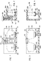
Figuren 13 bis 18 zeigen eine weitere Ausführungsform einer Brillenhalterung mit einem hinter einem Innenrückspiegel angeordneten Schutzgehäuse, wobei bei dieser Ausführungsform an der Brillenhalterung eine zusätzliche Vorrichtung zum Ein- bzw. Ausklappen der Brillenbügel angeordnet ist.FIGS. 13 to 18 show a further embodiment of an eyeglass holder with a protective housing arranged behind an interior rear-view mirror, in this embodiment an additional device for folding in and out the eyeglass temples is arranged on the eyeglass holder.
In den Figuren 13 bis 16 ist das Schutzgehäuse 800 über ein Konsolenstück 810 am Dach der Kfzg-Karosserie 820 befestigt. Im Schutzgehäuse 800 ist ein Rückspiegel 825 integirert. Das Schutzgehäuse 800 weist an seiner unteren Breitseite 830 eine Gehäuseöffnung 835 auf. Ueber Parallelführungen 840, 845 ist der Träger 850 drehbeweglich mit dem Schutzgehäuse 800 verbunden. Die Parallelführungen 840, 845 können um Lager 855 welche an den Seitenwänden 857 des Schutzgehäuses 800 und an Seitenwänden 853 des Trägers 850 angeordnet sind, drehen.In FIGS. 13 to 16, the
In der inneren Raststellung ist der Träger 850 im Schutzgehäuse 800 eingeschlossen. Die Abdeckung 851 auf der Unterseite des Trägers 850 verdeckt dabei im wesentlichen die Gehäuseöffnung 835 des Schutzgehäuses 800. Nach manuellem Lösen der Verriegelung 859, welche in der Verschlussleiste 858 des Trägers 850 angeordnet ist, bewegt sich dieser unter Einwirkung der Kraft einer Schenkelfeder 861 nach unten aus dem Schutzgehäuse 800 in seine äussere Raststellung. Durch eine Dämpfung 862 wird dabei die Bewegung gedämpft. Zum Schliessen wird der Träger 850 an der Verschlussleiste 858 aus der äusseren Raststellung gegen die Kraft der Schenkelfeder 861 ins Schutzgehäuse 800 zurückgeschoben, bis die Verriegelung 859 im Schutzgehäuse 800 einrastet.In the inner detent position, the
Der Träger 850 hat einen L-förmigen Querschnitt, welcher durch die Rückwand 865 und die Abdeckung 851 gebildet und auf seinen Stirnseiten durch die beiden Seitenwände 853 abgeschlossen wird. Eine Abstützwand 869 erstreckt sich senkrecht von der Abdeckung 851 nach oben und parallel zur Rückwand 865. Gemeinsam mit dieser bildet sie die Brillenhalterung. In der Mitte sind die Rückwand 865 und die Abstützwand 869 über eine Zentrierung 870 miteinander verbunden, welche in den Nasenausschnitt 871 einer eingesetzten Brille 877 eingreift und diese in der Brillenhalterung zentriert. Die Abstützwand 869 weist an ihren seitlichen Enden 870, 871 Durchbrüche 872, 873 für die Brillenbügel 874 auf, welche sich im wesentlichen über die Höhe der Abstützwand 869 erstrecken. Im Bereich der Durchbrüche 872, 873 sind Arme 875, 885 angeordnet, welche über Drehachsen 876 in der Abdeckung 851 drehbar gelagert sind. Die Brillenbügel 874 werden beim Einlegen der Brille 877 zwischen die Mitnehmer 880, 881 der Arme 875, 885 eingesetzt und beim Drehen der Arme 875, 885 um die Drehachsen 876 hinter der Abstützwand 869 auf- bzw. zugeklappt. Beim Entnehmen der Brille 877 wird diese nach oben aus der Brillenhalterung gehoben und dabei die Brillenbügel 874 aus den Mitnehmern 880, 881 herausgezogen.The
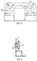
In den Figuren 17 und 18 wird die Steuerung der Drehbewegung der Arme 875, 885 durch die Relativbewegung zwischen dem Schutzgehäuse 800 und dem Träger 850 beim Oeffnen und Schliessen der Vorrichtung dargestellt.FIGS. 17 and 18 show the control of the rotary movement of the
Die Drehachsen 876 sind unterhalb der Abdeckung 851 mit Zahnrädern 890 verbunden. An der Rückwand 865 des Trägers 850 sind Dreharme 891 gelagert, welche an ihren oberen Enden Steuernocken 892 und an ihren unteren Enden Zahnsegmente 893 aufweisen, welche mit den Zahnrädern 890 kämmen.The axes of
An der Rückwand 800a des Schutzgehäuses 800 sind Rippen 894 mit Steuerkurven 895 angeordnet. Schenkelfedern 986 drücken die Arme 875, 885 in eine Stellung parallel zur Ausfahrbewegung des Trägers 850 aus dem Schutzgehäuse 800. Beim Einfahren des Trägers 850 ins Schutzgehäuse 800 treffen die Steuernocken 892 auf die Steuerkurven 895, welche die Steuernocken 892 um 90° abdrehen. Ueber die Zahnsegmente 893 werden dabei die Zahnräder 890 und damit die Arme 875, 885 gegen die Kräfte der Schenkelfeder 896 ebenfalls um 90° in eine Stellung parallel zur Rückwand 865 des Trägers 850 abgedreht. Diese Drehung erfolgt, bevor die Brillenbügel 874 einer eingesetzten Brille 877 das Schutzgehäuse 800 berühren können.
Die äussere Raststellung des Trägers 850 wird durch einen Anschlag 900, gegen den die Kraft der Feder 861 die Parallelführung 840 drückt, bestimmt. Dabei ist der Drehwinkel der Parallelführungen 840, 845 so festgelegt, dass der Träger 850 und damit die Brillenhalterung in ihrer äusseren Raststellung vor den Rückspiegel 825 zu liegen kommt, sodass die Brille 877 bequem eingesetzt bzw. entnommen werden kann.The outer latching position of the
Durch die Parallelführungen 840, 845 wird dafür gesorgt, dass die Brillenhalterung während ihrer Schwenkbewegung in paralleler Lage gehalten wird.The parallel guides 840, 845 ensure that the glasses holder is held in a parallel position during its pivoting movement.
Claims (10)
Applications Claiming Priority (13)
| Application Number | Priority Date | Filing Date | Title |
|---|---|---|---|
| CH44693A CH685844A5 (en) | 1993-02-15 | 1993-02-15 | Interior rear view mirror in vehicle with integrated storage compartment |
| CH44693 | 1993-02-15 | ||
| CH140393 | 1993-05-07 | ||
| CH1403/93 | 1993-05-07 | ||
| CH140393 | 1993-05-07 | ||
| CH181393 | 1993-06-18 | ||
| CH181393 | 1993-06-18 | ||
| CH1813/93 | 1993-06-18 | ||
| CH446/93 | 1993-11-18 | ||
| CH3451/93 | 1993-11-19 | ||
| CH345193 | 1993-11-19 | ||
| CH345193 | 1993-11-19 | ||
| EP94908311A EP0636070B1 (en) | 1993-02-15 | 1994-02-15 | Retaining device for spectacles, in particular for installation in motor vehicles |
Related Parent Applications (2)
| Application Number | Title | Priority Date | Filing Date |
|---|---|---|---|
| EP94908311A Division EP0636070B1 (en) | 1993-02-15 | 1994-02-15 | Retaining device for spectacles, in particular for installation in motor vehicles |
| EP94908311.7 Division | 1994-02-15 |
Publications (2)
| Publication Number | Publication Date |
|---|---|
| EP0721859A1 true EP0721859A1 (en) | 1996-07-17 |
| EP0721859B1 EP0721859B1 (en) | 1999-08-04 |
Family
ID=27427883
Family Applications (3)
| Application Number | Title | Priority Date | Filing Date |
|---|---|---|---|
| EP94908312A Expired - Lifetime EP0636069B1 (en) | 1993-02-15 | 1994-02-15 | Motor vehicle inner rearview mirror with integrated glove box |
| EP96103367A Expired - Lifetime EP0721859B1 (en) | 1993-02-15 | 1994-02-15 | Spectacles dolder in particular for installation in motor vehicles |
| EP94908311A Expired - Lifetime EP0636070B1 (en) | 1993-02-15 | 1994-02-15 | Retaining device for spectacles, in particular for installation in motor vehicles |
Family Applications Before (1)
| Application Number | Title | Priority Date | Filing Date |
|---|---|---|---|
| EP94908312A Expired - Lifetime EP0636069B1 (en) | 1993-02-15 | 1994-02-15 | Motor vehicle inner rearview mirror with integrated glove box |
Family Applications After (1)
| Application Number | Title | Priority Date | Filing Date |
|---|---|---|---|
| EP94908311A Expired - Lifetime EP0636070B1 (en) | 1993-02-15 | 1994-02-15 | Retaining device for spectacles, in particular for installation in motor vehicles |
Country Status (17)
| Country | Link |
|---|---|
| US (2) | US5507461A (en) |
| EP (3) | EP0636069B1 (en) |
| JP (2) | JP2710694B2 (en) |
| KR (2) | KR950700836A (en) |
| AT (2) | ATE137449T1 (en) |
| AU (2) | AU667772B2 (en) |
| BR (2) | BR9404118A (en) |
| CA (2) | CA2130175A1 (en) |
| CZ (2) | CZ280394A3 (en) |
| DE (3) | DE59400248D1 (en) |
| ES (2) | ES2088318T3 (en) |
| HU (2) | HU213713B (en) |
| PL (2) | PL305549A1 (en) |
| RU (1) | RU2095259C1 (en) |
| SG (1) | SG43203A1 (en) |
| SK (2) | SK120894A3 (en) |
| WO (2) | WO1994018032A1 (en) |
Cited By (5)
| Publication number | Priority date | Publication date | Assignee | Title |
|---|---|---|---|---|
| DE19720364A1 (en) * | 1997-05-15 | 1998-11-19 | Fischer Artur Werke Gmbh | Container for glasses to be installed in a vehicle |
| EP0947387A1 (en) * | 1998-03-30 | 1999-10-06 | Renzo Crescenzi | Burglary-proof convenience key-holding receptacle for motor-vehicles |
| DE19746197C2 (en) * | 1997-10-18 | 2003-04-10 | Johnson Contr Interiors Gmbh | receiving compartment |
| NL1027228C2 (en) * | 2004-10-12 | 2006-04-13 | Theyo Fa | Spectacle holder for temporarily stowing away a pair of spectacles comprises an upturned edge against which the spectacles rest |
| EP2404783A1 (en) * | 2010-07-09 | 2012-01-11 | Delphi Technologies, Inc. | Roof module with storage assembly |
Families Citing this family (17)
| Publication number | Priority date | Publication date | Assignee | Title |
|---|---|---|---|---|
| EP0890479A1 (en) * | 1997-07-09 | 1999-01-13 | Rover Group Limited | A stowage unit for a vehicle |
| GB9714379D0 (en) * | 1997-07-09 | 1997-09-10 | Rover Group | A stowage unit for a vehicle |
| US6428172B1 (en) * | 1999-11-24 | 2002-08-06 | Donnelly Corporation | Rearview mirror assembly with utility functions |
| ATE330818T1 (en) * | 1999-11-24 | 2006-07-15 | Donnelly Corp | REARVIEW MIRROR WITH USEFUL FUNCTION |
| US7380852B2 (en) * | 2006-02-14 | 2008-06-03 | Innotec Corporation | Overhead console with storage bin |
| KR100867255B1 (en) * | 2007-08-24 | 2008-11-06 | 지엠대우오토앤테크놀로지주식회사 | Overhead console for vehicle |
| CZ2009321A3 (en) * | 2009-05-21 | 2010-12-01 | Škoda Auto a. s. | Spectacle ceiling receptacle |
| US9073494B1 (en) * | 2014-06-04 | 2015-07-07 | Ford Global Technologies, Llc | Vehicle interior conversation mirror assembly |
| WO2018045306A1 (en) * | 2016-09-02 | 2018-03-08 | Gentex Corporation | Method of cooling full display mirror |
| US10746959B2 (en) * | 2017-02-27 | 2020-08-18 | Gentex Corporation | Fanless cooling system for full display mirror |
| EP3501901B1 (en) * | 2017-12-19 | 2020-08-12 | Dav | Storage housing, especially for glasses, and roof module comprising such a storage housing |
| US11353765B2 (en) | 2018-03-27 | 2022-06-07 | Gentex Corporation | Full display mirror with integrated cooling system |
| DE102018108216A1 (en) * | 2018-04-06 | 2019-10-10 | Nicola Berardi | Storage device for a pair of glasses |
| US10582794B1 (en) | 2018-10-17 | 2020-03-10 | Len Ekkert | Eyewear holder |
| RU2708966C1 (en) * | 2019-03-15 | 2019-12-12 | Открытое акционерное общество "Суксунский оптико-механический завод" | Protective goggles, closed type |
| RU2708969C1 (en) * | 2019-03-21 | 2019-12-12 | Открытое акционерное общество "Суксунский оптико-механический завод" | Safety open type glasses |
| CN116022158B (en) * | 2023-03-30 | 2023-06-06 | 深圳曦华科技有限公司 | Driving safety control method and device for cooperation of multi-domain controller |
Citations (6)
| Publication number | Priority date | Publication date | Assignee | Title |
|---|---|---|---|---|
| GB522357A (en) * | 1938-12-06 | 1940-06-17 | Thomas Charles Duncan | Improvements in and relating to cases or containers for spectacles, eye-glasses and the like sight improving or correcting devices |
| US2692043A (en) * | 1953-08-06 | 1954-10-19 | Lillian A Davis | Spectacle case |
| FR1517848A (en) * | 1966-12-29 | 1968-03-22 | Pecazaux & Kreutler La Mecaniq | Ashtray for motor vehicles combined with the rear view mirror |
| US4275913A (en) * | 1979-04-19 | 1981-06-30 | Prince Corporation | Vehicle storage receptacle |
| FR2648770A1 (en) * | 1989-06-27 | 1990-12-28 | Renault | Articulated storage container for motor vehicles |
| DE4122472A1 (en) * | 1991-07-06 | 1993-01-07 | Daimler Benz Ag | Compartment for storing spectacles in vehicle - which comprises gear and shaft mechanism for folding frame side pieces |
Family Cites Families (25)
| Publication number | Priority date | Publication date | Assignee | Title |
|---|---|---|---|---|
| US412822A (en) * | 1889-10-15 | Bag-holder | ||
| US2649028A (en) * | 1951-02-02 | 1953-08-18 | Joseph G Lenta | Rearview mirror |
| US2884219A (en) * | 1955-01-24 | 1959-04-28 | Anthony D Glover | Clip for holding spectacles or the like |
| DE1256655B (en) * | 1966-04-01 | 1967-12-21 | Goebel Gmbh Maschf | Device for driving a web in a rotary printing press for printing changing formats |
| US3588233A (en) * | 1968-07-09 | 1971-06-28 | Visor Mirror Corp | Extendable sun visor mirror |
| FR2212118B3 (en) * | 1973-01-03 | 1976-01-09 | Vanackere Florent Fr | |
| US3977774A (en) * | 1975-01-30 | 1976-08-31 | Sullivan Bernard O | Vehicle rear view mirror with slidable parallel sections |
| FR2351631A1 (en) * | 1976-05-20 | 1977-12-16 | Guichard Ets Rene | SUPPORT DEVICE FOR PRESENTATION OF GLASSES |
| JPS55145039A (en) * | 1979-05-01 | 1980-11-12 | Tokyo Tatsuno Co Ltd | Side mirror for automobile |
| DE2951942A1 (en) * | 1979-12-22 | 1981-07-02 | Günter 7530 Pforzheim Hirsch | Stand holding spectacle frame - has base with carrier having spring clamps at end to hold frame at top and bottom clamp ends may be curved |
| JPS574440A (en) * | 1980-06-10 | 1982-01-11 | Isamu Kuramochi | Side mirror mounted in cover of driving mirror and movable in and out |
| US4576320A (en) * | 1984-11-29 | 1986-03-18 | Mead F Jerome | Eyeglass holder for operative association with the rear view mirror on a vehicle |
| US4695026A (en) * | 1986-03-03 | 1987-09-22 | Medley Jr Travis D | Holder for eye glasses |
| US4715575A (en) * | 1986-12-10 | 1987-12-29 | Larry Kamerer | Eyeglass holder |
| GB8809677D0 (en) * | 1988-04-25 | 1988-06-02 | Clark J | Warm air bathroom mirror |
| US4867402A (en) * | 1988-08-19 | 1989-09-19 | Benson Steven B | Receptacle for eyeglasses |
| US4946125A (en) * | 1989-06-26 | 1990-08-07 | Mccarty Allan | Eyeglass holder |
| US4890907A (en) * | 1989-07-10 | 1990-01-02 | Vu Thuan D | Automatic mirror light |
| EP0407638A1 (en) * | 1989-07-12 | 1991-01-16 | Tsai-Fu Hu | Telescopic exterior rear view mirror |
| US4998812A (en) * | 1989-07-12 | 1991-03-12 | Hou Mei Wen H | Telescopic exterior rear view mirror |
| AU5985190A (en) * | 1989-07-18 | 1991-03-28 | Tsai-Fu Hu | Telescopic exterior rear view mirror |
| US5059015A (en) * | 1990-07-20 | 1991-10-22 | Tran Donald Q | Vehicular signal mirror apparatus |
| US5033709A (en) * | 1990-08-29 | 1991-07-23 | Yuen Michael M | Holding device |
| US5137242A (en) * | 1991-01-04 | 1992-08-11 | Reath Vern M | Holder for spectacles |
| US5372345A (en) * | 1993-06-16 | 1994-12-13 | Schmidt; Ray T. | Eyeglass holder |
-
1994
- 1994-02-15 BR BR9404118A patent/BR9404118A/en not_active Application Discontinuation
- 1994-02-15 PL PL30554994A patent/PL305549A1/en unknown
- 1994-02-15 DE DE59400248T patent/DE59400248D1/en not_active Expired - Fee Related
- 1994-02-15 AU AU61400/94A patent/AU667772B2/en not_active Ceased
- 1994-02-15 WO PCT/EP1994/000431 patent/WO1994018032A1/en active IP Right Grant
- 1994-02-15 SK SK1208-94A patent/SK120894A3/en unknown
- 1994-02-15 HU HU9401376A patent/HU213713B/en not_active IP Right Cessation
- 1994-02-15 CA CA002130175A patent/CA2130175A1/en not_active Abandoned
- 1994-02-15 CZ CZ942803A patent/CZ280394A3/en unknown
- 1994-02-15 US US08/256,306 patent/US5507461A/en not_active Expired - Fee Related
- 1994-02-15 JP JP6517680A patent/JP2710694B2/en not_active Expired - Lifetime
- 1994-02-15 AU AU61401/94A patent/AU660388B2/en not_active Ceased
- 1994-02-15 EP EP94908312A patent/EP0636069B1/en not_active Expired - Lifetime
- 1994-02-15 SK SK1236-94A patent/SK123694A3/en unknown
- 1994-02-15 AT AT94908312T patent/ATE137449T1/en not_active IP Right Cessation
- 1994-02-15 JP JP6517681A patent/JPH07505108A/en active Pending
- 1994-02-15 RU RU9494045936A patent/RU2095259C1/en active
- 1994-02-15 EP EP96103367A patent/EP0721859B1/en not_active Expired - Lifetime
- 1994-02-15 WO PCT/EP1994/000432 patent/WO1994018031A1/en not_active Application Discontinuation
- 1994-02-15 EP EP94908311A patent/EP0636070B1/en not_active Expired - Lifetime
- 1994-02-15 CA CA002130085A patent/CA2130085A1/en not_active Abandoned
- 1994-02-15 CZ CZ942802A patent/CZ285445B6/en not_active IP Right Cessation
- 1994-02-15 PL PL94304825A patent/PL304825A1/en unknown
- 1994-02-15 BR BR9404117A patent/BR9404117A/en not_active Application Discontinuation
- 1994-02-15 SG SG1996005373A patent/SG43203A1/en unknown
- 1994-02-15 DE DE59403849T patent/DE59403849D1/en not_active Expired - Fee Related
- 1994-02-15 AT AT94908311T patent/ATE157307T1/en not_active IP Right Cessation
- 1994-02-15 HU HU9401375A patent/HUT68487A/en unknown
- 1994-02-15 ES ES94908312T patent/ES2088318T3/en not_active Expired - Lifetime
- 1994-02-15 ES ES94908311T patent/ES2107814T3/en not_active Expired - Lifetime
- 1994-02-15 DE DE59408593T patent/DE59408593D1/en not_active Expired - Fee Related
- 1994-02-15 US US08/256,644 patent/US5719714A/en not_active Expired - Fee Related
- 1994-09-16 KR KR1019940703228A patent/KR950700836A/en not_active Application Discontinuation
- 1994-10-12 KR KR1019940703618A patent/KR950700835A/en not_active Application Discontinuation
Patent Citations (6)
| Publication number | Priority date | Publication date | Assignee | Title |
|---|---|---|---|---|
| GB522357A (en) * | 1938-12-06 | 1940-06-17 | Thomas Charles Duncan | Improvements in and relating to cases or containers for spectacles, eye-glasses and the like sight improving or correcting devices |
| US2692043A (en) * | 1953-08-06 | 1954-10-19 | Lillian A Davis | Spectacle case |
| FR1517848A (en) * | 1966-12-29 | 1968-03-22 | Pecazaux & Kreutler La Mecaniq | Ashtray for motor vehicles combined with the rear view mirror |
| US4275913A (en) * | 1979-04-19 | 1981-06-30 | Prince Corporation | Vehicle storage receptacle |
| FR2648770A1 (en) * | 1989-06-27 | 1990-12-28 | Renault | Articulated storage container for motor vehicles |
| DE4122472A1 (en) * | 1991-07-06 | 1993-01-07 | Daimler Benz Ag | Compartment for storing spectacles in vehicle - which comprises gear and shaft mechanism for folding frame side pieces |
Cited By (5)
| Publication number | Priority date | Publication date | Assignee | Title |
|---|---|---|---|---|
| DE19720364A1 (en) * | 1997-05-15 | 1998-11-19 | Fischer Artur Werke Gmbh | Container for glasses to be installed in a vehicle |
| DE19746197C2 (en) * | 1997-10-18 | 2003-04-10 | Johnson Contr Interiors Gmbh | receiving compartment |
| EP0947387A1 (en) * | 1998-03-30 | 1999-10-06 | Renzo Crescenzi | Burglary-proof convenience key-holding receptacle for motor-vehicles |
| NL1027228C2 (en) * | 2004-10-12 | 2006-04-13 | Theyo Fa | Spectacle holder for temporarily stowing away a pair of spectacles comprises an upturned edge against which the spectacles rest |
| EP2404783A1 (en) * | 2010-07-09 | 2012-01-11 | Delphi Technologies, Inc. | Roof module with storage assembly |
Also Published As
Similar Documents
| Publication | Publication Date | Title |
|---|---|---|
| EP0721859A1 (en) | Spectacles dolder in particular for installation in motor vehicles | |
| EP0981465B1 (en) | Spectacle case built into a vehicle | |
| EP0587014B1 (en) | Center console for vehicle | |
| DE69911542T2 (en) | Auto device anti-theft protection with hinged flap | |
| DE4431328A1 (en) | Spectacles, in particular sports and / or leisure glasses | |
| DE8004810U1 (en) | EYE GLASS MOUNT BRACKET | |
| EP0035596A1 (en) | Sun visor, especially for vehicles | |
| DE2446562A1 (en) | PROTECTIVE MASK FOR SKIERS | |
| DE10323727B4 (en) | Sun visor mirror arrangement | |
| EP0449056B1 (en) | Exterior mirror for lorries | |
| DE102016209168A1 (en) | Tablet holder for a motor vehicle | |
| DE102006043540B3 (en) | Sun visor for vehicle, particularly for receiving eyeglasses or flat objects, has longitudinal visor body, longitudinal side borders, where visor body moves between non-operational position and operational position | |
| DE102005052183A1 (en) | Vehicle sun visors with mirrors | |
| EP2380058A1 (en) | Foldable spectacles having a spectacle housing | |
| DE8110470U1 (en) | VISOR DEVICE FOR MOTOR VEHICLES WITH A MOVABLE FASTENABLE SUN VISOR | |
| EP0771434B1 (en) | Device for securing decorative strips to spectacle lenses or frames | |
| EP1039259A2 (en) | Manhole cover for armoured vehicle | |
| DE102005058393A1 (en) | helmet | |
| DE3637373A1 (en) | Protective motorcyclist's helmet with two visors | |
| DE3825642C1 (en) | ||
| CH685844A5 (en) | Interior rear view mirror in vehicle with integrated storage compartment | |
| DE4114055A1 (en) | Parking disc for in vehicle display - has housing hinged to cover that can be fitted to sun visor and may be covered when not in use and is accessible for time setting | |
| DE19543509C1 (en) | Spectacles frame with body for holding lenses | |
| DE10017158A1 (en) | Adjustable internal rear view mirror esp. for motor vehicles has freely accessible container fastened detachable to back of mirror housing to hold spectacles etc. | |
| DE4218008C2 (en) | Glasses storage bracket |
Legal Events
| Date | Code | Title | Description |
|---|---|---|---|
| PUAI | Public reference made under article 153(3) epc to a published international application that has entered the european phase |
Free format text: ORIGINAL CODE: 0009012 |
|
| AC | Divisional application: reference to earlier application |
Ref document number: 636070 Country of ref document: EP |
|
| AK | Designated contracting states |
Kind code of ref document: A1 Designated state(s): DE ES FR GB IT PT SE |
|
| 17P | Request for examination filed |
Effective date: 19961120 |
|
| 17Q | First examination report despatched |
Effective date: 19980909 |
|
| GRAG | Despatch of communication of intention to grant |
Free format text: ORIGINAL CODE: EPIDOS AGRA |
|
| GRAG | Despatch of communication of intention to grant |
Free format text: ORIGINAL CODE: EPIDOS AGRA |
|
| GRAH | Despatch of communication of intention to grant a patent |
Free format text: ORIGINAL CODE: EPIDOS IGRA |
|
| GRAH | Despatch of communication of intention to grant a patent |
Free format text: ORIGINAL CODE: EPIDOS IGRA |
|
| GRAA | (expected) grant |
Free format text: ORIGINAL CODE: 0009210 |
|
| AC | Divisional application: reference to earlier application |
Ref document number: 636070 Country of ref document: EP |
|
| AK | Designated contracting states |
Kind code of ref document: B1 Designated state(s): DE ES FR GB IT PT SE |
|
| PG25 | Lapsed in a contracting state [announced via postgrant information from national office to epo] |
Ref country code: SE Free format text: THE PATENT HAS BEEN ANNULLED BY A DECISION OF A NATIONAL AUTHORITY Effective date: 19990804 |
|
| ET | Fr: translation filed | ||
| REF | Corresponds to: |
Ref document number: 59408593 Country of ref document: DE Date of ref document: 19990909 |
|
| ITF | It: translation for a ep patent filed |
Owner name: ING. ZINI MARANESI & C. S.R.L. |
|
| PG25 | Lapsed in a contracting state [announced via postgrant information from national office to epo] |
Ref country code: PT Free format text: LAPSE BECAUSE OF FAILURE TO SUBMIT A TRANSLATION OF THE DESCRIPTION OR TO PAY THE FEE WITHIN THE PRESCRIBED TIME-LIMIT Effective date: 19991104 |
|
| GBT | Gb: translation of ep patent filed (gb section 77(6)(a)/1977) |
Effective date: 19991101 |
|
| REG | Reference to a national code |
Ref country code: ES Ref legal event code: FG2A Ref document number: 2137578 Country of ref document: ES Kind code of ref document: T3 |
|
| PG25 | Lapsed in a contracting state [announced via postgrant information from national office to epo] |
Ref country code: GB Free format text: LAPSE BECAUSE OF NON-PAYMENT OF DUE FEES Effective date: 20000215 |
|
| PG25 | Lapsed in a contracting state [announced via postgrant information from national office to epo] |
Ref country code: ES Free format text: LAPSE BECAUSE OF NON-PAYMENT OF DUE FEES Effective date: 20000216 |
|
| PLBE | No opposition filed within time limit |
Free format text: ORIGINAL CODE: 0009261 |
|
| STAA | Information on the status of an ep patent application or granted ep patent |
Free format text: STATUS: NO OPPOSITION FILED WITHIN TIME LIMIT |
|
| 26N | No opposition filed | ||
| GBPC | Gb: european patent ceased through non-payment of renewal fee |
Effective date: 20000215 |
|
| PGFP | Annual fee paid to national office [announced via postgrant information from national office to epo] |
Ref country code: DE Payment date: 20001206 Year of fee payment: 8 |
|
| PG25 | Lapsed in a contracting state [announced via postgrant information from national office to epo] |
Ref country code: FR Free format text: LAPSE BECAUSE OF NON-PAYMENT OF DUE FEES Effective date: 20011031 |
|
| REG | Reference to a national code |
Ref country code: FR Ref legal event code: ST |
|
| PG25 | Lapsed in a contracting state [announced via postgrant information from national office to epo] |
Ref country code: DE Free format text: LAPSE BECAUSE OF NON-PAYMENT OF DUE FEES Effective date: 20020903 |
|
| REG | Reference to a national code |
Ref country code: ES Ref legal event code: FD2A Effective date: 20020916 |
|
| PG25 | Lapsed in a contracting state [announced via postgrant information from national office to epo] |
Ref country code: IT Free format text: LAPSE BECAUSE OF NON-PAYMENT OF DUE FEES;WARNING: LAPSES OF ITALIAN PATENTS WITH EFFECTIVE DATE BEFORE 2007 MAY HAVE OCCURRED AT ANY TIME BEFORE 2007. THE CORRECT EFFECTIVE DATE MAY BE DIFFERENT FROM THE ONE RECORDED. Effective date: 20050215 |
|
| PG25 | Lapsed in a contracting state [announced via postgrant information from national office to epo] |
Ref country code: FR Free format text: LAPSE BECAUSE OF NON-PAYMENT OF DUE FEES Effective date: 20000229 |