EP0719926A2 - Regelungssystem für die Brennstoffdosierung eines Innenverbrennungsmotors - Google Patents
Regelungssystem für die Brennstoffdosierung eines Innenverbrennungsmotors Download PDFInfo
- Publication number
- EP0719926A2 EP0719926A2 EP96300012A EP96300012A EP0719926A2 EP 0719926 A2 EP0719926 A2 EP 0719926A2 EP 96300012 A EP96300012 A EP 96300012A EP 96300012 A EP96300012 A EP 96300012A EP 0719926 A2 EP0719926 A2 EP 0719926A2
- Authority
- EP
- European Patent Office
- Prior art keywords
- fuel
- air
- correction coefficient
- engine
- fuel ratio
- Prior art date
- Legal status (The legal status is an assumption and is not a legal conclusion. Google has not performed a legal analysis and makes no representation as to the accuracy of the status listed.)
- Withdrawn
Links
Images


Classifications
-
- F—MECHANICAL ENGINEERING; LIGHTING; HEATING; WEAPONS; BLASTING
- F02—COMBUSTION ENGINES; HOT-GAS OR COMBUSTION-PRODUCT ENGINE PLANTS
- F02D—CONTROLLING COMBUSTION ENGINES
- F02D41/00—Electrical control of supply of combustible mixture or its constituents
- F02D41/008—Controlling each cylinder individually
-
- F—MECHANICAL ENGINEERING; LIGHTING; HEATING; WEAPONS; BLASTING
- F02—COMBUSTION ENGINES; HOT-GAS OR COMBUSTION-PRODUCT ENGINE PLANTS
- F02D—CONTROLLING COMBUSTION ENGINES
- F02D41/00—Electrical control of supply of combustible mixture or its constituents
- F02D41/0025—Controlling engines characterised by use of non-liquid fuels, pluralities of fuels, or non-fuel substances added to the combustible mixtures
- F02D41/003—Adding fuel vapours, e.g. drawn from engine fuel reservoir
- F02D41/0042—Controlling the combustible mixture as a function of the canister purging, e.g. control of injected fuel to compensate for deviation of air fuel ratio when purging
-
- F—MECHANICAL ENGINEERING; LIGHTING; HEATING; WEAPONS; BLASTING
- F02—COMBUSTION ENGINES; HOT-GAS OR COMBUSTION-PRODUCT ENGINE PLANTS
- F02D—CONTROLLING COMBUSTION ENGINES
- F02D41/00—Electrical control of supply of combustible mixture or its constituents
- F02D41/0025—Controlling engines characterised by use of non-liquid fuels, pluralities of fuels, or non-fuel substances added to the combustible mixtures
- F02D41/0047—Controlling exhaust gas recirculation [EGR]
- F02D41/0065—Specific aspects of external EGR control
- F02D41/0072—Estimating, calculating or determining the EGR rate, amount or flow
-
- F—MECHANICAL ENGINEERING; LIGHTING; HEATING; WEAPONS; BLASTING
- F02—COMBUSTION ENGINES; HOT-GAS OR COMBUSTION-PRODUCT ENGINE PLANTS
- F02D—CONTROLLING COMBUSTION ENGINES
- F02D41/00—Electrical control of supply of combustible mixture or its constituents
- F02D41/009—Electrical control of supply of combustible mixture or its constituents using means for generating position or synchronisation signals
-
- F—MECHANICAL ENGINEERING; LIGHTING; HEATING; WEAPONS; BLASTING
- F02—COMBUSTION ENGINES; HOT-GAS OR COMBUSTION-PRODUCT ENGINE PLANTS
- F02D—CONTROLLING COMBUSTION ENGINES
- F02D41/00—Electrical control of supply of combustible mixture or its constituents
- F02D41/02—Circuit arrangements for generating control signals
- F02D41/04—Introducing corrections for particular operating conditions
- F02D41/045—Detection of accelerating or decelerating state
-
- F—MECHANICAL ENGINEERING; LIGHTING; HEATING; WEAPONS; BLASTING
- F02—COMBUSTION ENGINES; HOT-GAS OR COMBUSTION-PRODUCT ENGINE PLANTS
- F02D—CONTROLLING COMBUSTION ENGINES
- F02D41/00—Electrical control of supply of combustible mixture or its constituents
- F02D41/02—Circuit arrangements for generating control signals
- F02D41/14—Introducing closed-loop corrections
- F02D41/1401—Introducing closed-loop corrections characterised by the control or regulation method
- F02D41/1402—Adaptive control
-
- F—MECHANICAL ENGINEERING; LIGHTING; HEATING; WEAPONS; BLASTING
- F02—COMBUSTION ENGINES; HOT-GAS OR COMBUSTION-PRODUCT ENGINE PLANTS
- F02D—CONTROLLING COMBUSTION ENGINES
- F02D41/00—Electrical control of supply of combustible mixture or its constituents
- F02D41/02—Circuit arrangements for generating control signals
- F02D41/14—Introducing closed-loop corrections
- F02D41/1401—Introducing closed-loop corrections characterised by the control or regulation method
- F02D2041/1409—Introducing closed-loop corrections characterised by the control or regulation method using at least a proportional, integral or derivative controller
-
- F—MECHANICAL ENGINEERING; LIGHTING; HEATING; WEAPONS; BLASTING
- F02—COMBUSTION ENGINES; HOT-GAS OR COMBUSTION-PRODUCT ENGINE PLANTS
- F02D—CONTROLLING COMBUSTION ENGINES
- F02D41/00—Electrical control of supply of combustible mixture or its constituents
- F02D41/02—Circuit arrangements for generating control signals
- F02D41/14—Introducing closed-loop corrections
- F02D41/1401—Introducing closed-loop corrections characterised by the control or regulation method
- F02D2041/1413—Controller structures or design
- F02D2041/1415—Controller structures or design using a state feedback or a state space representation
- F02D2041/1416—Observer
-
- F—MECHANICAL ENGINEERING; LIGHTING; HEATING; WEAPONS; BLASTING
- F02—COMBUSTION ENGINES; HOT-GAS OR COMBUSTION-PRODUCT ENGINE PLANTS
- F02D—CONTROLLING COMBUSTION ENGINES
- F02D41/00—Electrical control of supply of combustible mixture or its constituents
- F02D41/02—Circuit arrangements for generating control signals
- F02D41/14—Introducing closed-loop corrections
- F02D41/1401—Introducing closed-loop corrections characterised by the control or regulation method
- F02D2041/1413—Controller structures or design
- F02D2041/1418—Several control loops, either as alternatives or simultaneous
-
- F—MECHANICAL ENGINEERING; LIGHTING; HEATING; WEAPONS; BLASTING
- F02—COMBUSTION ENGINES; HOT-GAS OR COMBUSTION-PRODUCT ENGINE PLANTS
- F02D—CONTROLLING COMBUSTION ENGINES
- F02D41/00—Electrical control of supply of combustible mixture or its constituents
- F02D41/02—Circuit arrangements for generating control signals
- F02D41/14—Introducing closed-loop corrections
- F02D41/1401—Introducing closed-loop corrections characterised by the control or regulation method
- F02D2041/1413—Controller structures or design
- F02D2041/142—Controller structures or design using different types of control law in combination, e.g. adaptive combined with PID and sliding mode
-
- F—MECHANICAL ENGINEERING; LIGHTING; HEATING; WEAPONS; BLASTING
- F02—COMBUSTION ENGINES; HOT-GAS OR COMBUSTION-PRODUCT ENGINE PLANTS
- F02D—CONTROLLING COMBUSTION ENGINES
- F02D41/00—Electrical control of supply of combustible mixture or its constituents
- F02D41/02—Circuit arrangements for generating control signals
- F02D41/14—Introducing closed-loop corrections
- F02D41/1401—Introducing closed-loop corrections characterised by the control or regulation method
- F02D2041/1433—Introducing closed-loop corrections characterised by the control or regulation method using a model or simulation of the system
-
- Y—GENERAL TAGGING OF NEW TECHNOLOGICAL DEVELOPMENTS; GENERAL TAGGING OF CROSS-SECTIONAL TECHNOLOGIES SPANNING OVER SEVERAL SECTIONS OF THE IPC; TECHNICAL SUBJECTS COVERED BY FORMER USPC CROSS-REFERENCE ART COLLECTIONS [XRACs] AND DIGESTS
- Y02—TECHNOLOGIES OR APPLICATIONS FOR MITIGATION OR ADAPTATION AGAINST CLIMATE CHANGE
- Y02T—CLIMATE CHANGE MITIGATION TECHNOLOGIES RELATED TO TRANSPORTATION
- Y02T10/00—Road transport of goods or passengers
- Y02T10/10—Internal combustion engine [ICE] based vehicles
- Y02T10/40—Engine management systems
Definitions
- This invention relates to a fuel metering control system for an internal combustion engine.
- the amount of air or fuel is determined by using various correction factors which have initially been designed. Since, however, the correction factors have often been designed as general terms and have not been designed as countermeasures for a specific problem, when the air/fuel ratio deviates from a desired value, it is difficult to know that the deviation results from the determination of the amount of intake air, or from the fuel transport delay, or from the feedback system.
- An object of the invention is therefore to provide a fuel metering control system for an internal combustion engine provided with an air/fuel ratio sensor at its exhaust system which can solve the above problem and makes it possible to improve control performance, by classifying correction factors into one for determining the amount of intake air, one for fuel transport delay and one for feedback control such that they function independently, thereby enhancing the purification efficiency of the catalytic converter.
- This invention achieves this object by providing a system for controlling fuel metering for an internal combustion engine having an air intake system including a throttle valve, a plurality of cylinders, and an exhaust system, comprising, an air/fuel ratio sensor located in the exhaust system of the engine for detecting an air/fuel ratio of an exhaust gas of the engine, engine operating condition detecting means for detecting engine operating conditions including at least engine speed and engine load, basic fuel injection quantity determining means for determining basic a quantity of fuel injection for individual cylinders based on at least the detected engine operating conditions and a change in effective opening area of the throttle valve, a catalytic converter installed downstream of said air/fuel ratio sensor, a feedback loop for calculating a feedback correction coefficient to correct the basic quantity of fuel injection such that the detected air/fuel ratio detected by said air/fuel ratio sensor is brought to a desired air/fuel ratio, output fuel injection quantity determining means for correcting the basic quantity of fuel injection based on the feedback correction coefficient, to determine an output quantity of fuel injection, fuel adhesion correction means for determining an adhered
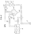
- Figure 1 is an overview of a fuel metering control system for an internal combustion engine according to the invention.
- Reference numeral 10 in this figure designates an overhead cam (OHC) in-line four-cylinder internal combustion engine.
- Air drawn into an air intake pipe 12 through an air cleaner 14 mounted on a far end thereof is supplied to the first to fourth cylinders through a surge tank 18, an intake manifold 20 and two intake valves (not shown), while the flow thereof is adjusted by a throttle valve 16.
- a fuel injector 22 for injecting fuel is installed in the vicinity of the intake valves of each cylinder. The injected fuel mixes with the intake air to form an air-fuel mixture that is ignited in the associated cylinder by a spark plug (not shown) in the firing order of #1, #3, #4 and #2 cylinder. The resulting combustion of the air-fuel mixture drives down a piston (not shown).
- the exhaust gas produced by the combustion is discharged through two exhaust valves (not shown) into an exhaust manifold 24, from where it passes through an exhaust pipe 26 to a first catalytic converter (three-way catalyst) 28 and a second catalytic converter 30 (also a three-way catalyst) where noxious components are removed therefrom before it is discharged to the external atmosphere.
- the throttle valve 16 is controlled to a desired degree of opening by a stepping motor M.
- the throttle valve 16 is bypassed by a bypass 32 provided at the air intake pipe 12 in the vicinity thereof.
- the engine 10 is equipped with an exhaust gas recirculation (EGR) mechanism 100 which recirculates a part of the exhaust gas to the intake side.
- EGR exhaust gas recirculation
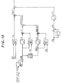
- the exhaust gas recirculation mechanism 100 has an exhaust gas recirculation pipe 121 having one end (port) 121a connected with the exhaust pipe 26 on the upstream side of the first catalytic converter 28 (not shown in Figure 2) and another end (port) 121b connected to the air intake pipe 12 on the downstream side of the throttle valve 16 (not shown in Figure 2).
- an EGR (exhaust gas recirculation) control valve 122 and a surge tank 121c are provided at an intermediate portion of the exhaust gas recirculation pipe 121.
- the EGR control valve 122 is a solenoid valve having a solenoid 122a which is connected to a control unit (ECU) 34 (described later).
- the EGR control valve 122 is linearly controlled to the desired degree of opening by an output from the control unit 34 to the solenoid 122a.
- the EGR control valve 122 is provided with a lift sensor 123 which detects the degree of opening of the EGR control valve 122 and sends a corresponding signal to the control unit 34.
- the engine 10 is also equipped with a canister purge mechanism 200 connected between the air intake system and a fuel tank 36.
- the canister purge mechanism 200 which is provided between the top of the sealed fuel tank 36 and a point on the air intake pipe 12 downstream of the throttle valve 16, comprises a vapor supply pipe 221, a canister 223 containing an absorbent 231, and a purge pipe 224.
- the vapor supply pipe 221 is fitted with a two-way valve 222
- the purge pipe 224 is fitted with a purge control valve 225, a flow meter 226 for measuring the amount of air-fuel mixture containing fuel vapor flowing through the purge pipe 224 and a hydrocarbon (HC) concentration sensor 227 for detecting the HC concentration of the air-fuel mixture.
- the purge control valve (solenoid valve) 225 is connected to the control unit 34 and is linearly controlled to the desired degree of opening by a signal from the control unit 34.
- the amount of fuel vapor generated in the fuel tank 36 reaches a prescribed level, it pushes open the positive pressure valve of the two-way valve 222 and flows into the canister 223, where it is stored by absorption on the absorbent 231. Then when the purge control valve 225 is opened to an amount corresponding to the duty ratio of the on/off signal from the control unit 34, the vaporized fuel temporarily stored in the canister 223 and air drawn in through an external air intake 232 are together sucked into the air intake pipe 12 owing to the negative pressure in the air intake pipe 12.
- the negative valve of the two-way valve 222 opens to allow the vaporized fuel temporarily stored in the canister 223 to return to the fuel tank 36.
- the engine 10 is also equipped with a variable valve timing mechanism 300 (denoted as V/T in Figure 1).
- V/T variable valve timing mechanism 300
- the variable valve timing mechanism 300 switches the opening/closing timing of the intake and/or exhaust valves between two types of timing characteristics, a characteristic for low engine speed designated LoV/T and a characteristic for high engine speed designated HiV/T, as illustrated in Figure 4, in response to engine speed Ne and manifold pressure Pb. Since this is a well-known mechanism, however, it will not be described further here. (Among the different ways of switching between valve timing characteristics is included that of deactivating one of the two intake valves.)
- the engine 10 of Figure 1 is provided in its ignition distributor (not shown) with a crank angle sensor 40 for detecting the piston crank angles and is further provided with a throttle position sensor 42 for detecting the degree of opening of the throttle valve 16, and a manifold absolute pressure sensor 44 for detecting the pressure Pb of the intake manifold downstream of the throttle valve 16 in terms of absolute value.
- An atmospheric pressure sensor 46 for detecting atmospheric pressure Pa is provided at an appropriate portion of the engine 10
- an intake air temperature sensor 48 for detecting the temperature of the intake air is provided upstream of the throttle valve 16
- a coolant temperature sensor 50 for detecting the temperature of the engine coolant is provided at an appropriate portion of the engine.
- the engine 10 is further provided with a valve timing (V/T) sensor 52 (not shown in Figure 1) which detects the valve timing characteristic selected by the variable valve timing mechanism 300 based on oil pressure.
- an air/fuel sensor 54 constituted as an oxygen detector or oxygen sensor is provided in the exhaust pipe 26 at, or downstream of, a confluence point in the exhaust system downstream of the exhaust manifold 24 and upstream of the first catalytic converter 28, where it detects the oxygen concentration in the exhaust gas at the confluence point and produces a corresponding signal (explained later).
- an O 2 sensor 56 is provided as a second oxygen sensor downstream of the air/fuel ratio sensor 54 (first oxygen sensor).
- the volume of the first and second catalysts are appropriately determined taking into account the purification (conversion) efficiency, and temperature characteristics and are set to be 1 liter or thereabout for the first catalyst and 1.7 liter or thereabout for the second one, for example.
- the first catalytic converter 28 may be configured to have a multiple of beds each carrying a catalyst, specifically dual beds in the illustration comprising a first catalyst bed and a second catalyst bed.
- the O 2 sensor 56 may be positioned between the first and second beds, as illustrated.
- the volume of the catalyst carried on the first bed is approximately 1 liter and that on the second bed is approximately 1 liter or so.
- the first catalytic converter 28 will accordingly have a volume of approximately 2.0 liters when thus configured in the manner as illustrated.
- the illustrated configuration is the same as the case in which the O 2 sensor is installed downstream of a single catalytic converter of 1.0 liter capacity, the sensor output switching interval will be shorter than the case in which the sensor is positioned downstream of a catalytic converter of 2.0 liters volume.
- the minute air/fuel ratio control is hereinafter referred to as "MID O 2 control”.
- the air/fuel ratio sensor 54 is followed by a filter 58 and the O 2 sensor 56 is followed by a second filter 60.
- the outputs of the sensors and filters are sent to the control unit 34.
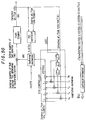
- control unit 34 Details of the control unit 34 are shown in the block diagram of Figure 6.
- the output of the air/fuel ratio sensor 54 is received by a first detection circuit 62, where it is subjected to appropriate linearization processing for producing an output characterized in that it varies linearly with the oxygen concentration of the exhaust gas over a broad range extending from the lean side to the rich side.
- the air/fuel ratio sensor is denoted as "LAF sensor” in the figure and will be so referred to in the remainder of this specification.
- the output of the first detection circuit 62 is forwarded through a multiplexer 66 and an A/D converter 68 to a CPU (central processing unit).
- the CPU has a CPU core 70, a ROM (read-only memory) 72 and a RAM (random access memory) 74, and the output of the first detection circuit 62 is A/D-converted once every prescribed crank angle (e.g., 15 degrees) and stored in buffers of the RAM 74.
- the RAM 74 has 12 buffers numbered 0 to 11 and the A/D-converted outputs from the detection circuit 62 are sequentially stored in the 12 buffers.
- the output of the second detection circuit 64 and the analog outputs of the throttle position sensor 42, etc. are input to the CPU through the multiplexer 66 and the A/D converter 68 and stored in the RAM 74.
- the output of the crank angle sensor 40 is shaped by a waveform shaper 76 and has its output value counted by a counter 78. The result of the count is input to the CPU.
- the CPU core 70 computes a manipulated variable in the manner described later and drives the fuel injectors 22 of the respective cylinders via a drive circuit 82.
- the CPU core 70 also drives a solenoid valve (EACV) 90 (for opening and closing the bypass 32 to regulate the amount of secondary air), the solenoid valve 122 for controlling the aforesaid exhaust gas recirculation, and the solenoid valve 225 for controlling the aforesaid canister purge.
- EACV solenoid valve
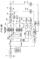
- Figure 8 is a block diagram showing the operation of the fuel metering control according to the embodiment.
- the system is provided with an observer (depicted as “OBSV” in the figure) that estimates the air/fuel ratios at the individual cylinders from the output of the single LAF sensor 54 installed at the exhaust system of the engine 10, and an adaptive controller (Self Tuning Regulator; shown as “STR” in the figure) that receives the output of the LAF sensor 54 through a filter 92.
- OBSV observer
- STR Self Tuning Regulator
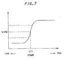
- the output of the O 2 sensor 56 is input to a desired air/fuel ratio correction block (shown as “KCMD correction” in the figure) where a desired air/fuel ratio correction coefficient named "KCMDM” is determined in accordance with an error between the O 2 sensor output VO 2 M" and a desired value (VrefM in Figure 7).
- KCMD correction a desired air/fuel ratio correction coefficient
- KCMDM a desired air/fuel ratio correction coefficient
- VrefM desired value
- the basic quantity of fuel injection TiM-F is determined on the basis of the change in the effective opening area of the throttle valve 16 in the manner explained later.
- the basic quantity of fuel injection TiM-F is multiplied by the desired air/fuel ratio correction coefficient KCMDM and another correction coefficient KTOTAL (the product of other correction coefficients including correction coefficients for EGR and canister purging) to determine the quantity of fuel injection assumed to be required by the engine (called “the required quantity of fuel injection Tcyl").
- the corrected desired air/fuel ratio KCMD is input to the adaptive controller STR and a PID controller (shown as "PID" in the figure) which respectively determine feedback correction coefficients named KSTR or KLAF in response to an error from the LAF sensor output. Either of the feedback correction coefficients is selected through a switch in response to the operating conditions of the engine and is multiplied by the required quantity of fuel injection Tcyl to determine the output quantity of fuel injection named Tout. The output quantity of fuel injection is then subject to fuel adhesion correction and the corrected quantity is finally supplied to the engine 10.
- PID controller shown as "PID” in the figure
- the air/fuel ratio is feedback controlled to the desired air/fuel ratio on the basis of the LAF sensor output, and the aforesaid MIDO 2 control is implemented at or about the desired air/fuel ratio, i.e., within the catalyst window.
- the catalyst functions to store O 2 from the exhaust gas of a relatively lean mixture. When the catalyst is saturated with O 2 , the purification efficiency drops. Therefore, it is necessary to provide exhaust gas of a relatively rich mixture so as to relieve the catalyst of the stored O 2 and upon the completion of the stored O 2 relief, the exhaust gas of a relatively lean mixture is newly provided. By repeating this, it is possible to maximize the purification efficiency.
- the MIDO 2 control aims to achieve this.
- the system disclosed accordingly, in order to solve the problem, is configured such that the response of the detected air/fuel ratio KACT is dynamically ensured. More specifically, the quantity of fuel injection is multiplied by the correction coefficient KSTR (output of the adaptive controller) that ensures the desired behavior of the desired air/fuel ratio KCMD. With the arrangement, it becomes possible to allow the detected air/fuel ratio KACT to immediately converge to the desired air/fuel ratio KCMD and to enhance the catalyst purification (conversion) efficiency.
- the configuration illustrated is constituted as a multi-imposed feedback control system where a plurality of feedback loops are provided in parallel all using a common output from the single LAF sensor 54. More precisely, the system is configured such that the multi-imposed or plural feedback loops are switched. Therefore, the frequency characteristics of the filters are determined in accordance with the nature of the feedback loops.
- the sensor outputs When left as they are, the sensor outputs include high frequency noise, and the control performance will degrade.
- the inventors have found, through experiments, that when the sensor outputs are passed through a low-pass filter whose cutoff frequency is 500 Hz, high frequency noise can be removed without substantially degrading response characteristics. When lowering the cutout frequency of a filter to 4 Hz, high frequency noise could further be reduced to a considerable extent and the time required for the 100 % response became stable. However, the response characteristics of the filter in that case were more delayed than the case where the sensor output was filtered or was passed through a filter of 500 Hz cutout frequency, and took 400 ms or more until the 100 % response had been obtained.
- the filter 58 is determined to be a low-pass filter having a cutout frequency of 500 Hz, and the sensor output passed to the filter is immediately input to the observer.
- the observer does not operate to converge the detected air/fuel ratio KACT to the desired air/fuel ratio KCMD. Rather, the system is configured such that the air/fuel ratios in the individual cylinders are estimated by the observer, while the variance between the individual cylinder air/fuel ratios are absorbed by the PID controller. As a result, even when the sensor response time is not stable, that will not affect the air/fuel detection. Rather, shorter response time will enhance control performance.
- the filter 92 placed before the adaptive controller STR should be a low-pass filter having a 4 Hz cutout frequency. This is because, since the dead-beat controller such as the STR operates to faithfully compensate the air/fuel ratio detection delay, any change in noise or response time in air/fuel detection would affect control performance. For that reason, the low-pass filter 92 is assigned with the cutout frequency of 4 Hz.
- the filter 93 placed before the input to the PID controller is to be a filter whose cutout frequency is equal to or greater than that of the filter 92, specifically 200 Hz, taking response time into account.
- the filter 60 connected to the O 2 sensor 56 is determined to be a low-pass filter whose cutout frequency is 1600 Hz, since the response of the O 2 sensor is much greater than that of the LAF sensor.
- the basic quantity of fuel injection TiM-F is determined or calculated.
- the basic quantity of fuel injection TiM-F is optimally determined in all engine operating conditions including engine transients, on the basis of the change in the effective throttle opening area.
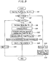
- Figure 9 is a flowchart for determining or calculating the basic quantity of fuel injection TiM-F
- Figure 10 is a block diagram explaining the operation shown in Figure 9.
- the throttle's projection area S (formed on a plane perpendicular to the longitudinal direction of the air intake pipe 12 when the throttle valve 16 is assumed to be projected in that direction) is determined in accordance with a predetermined characteristic, as illustrated in the block diagram of Figure 11.
- the discharge coefficient C which is the product of the flow rate coefficient ⁇ and gas expansion factor epsilon, is retrieved from mapped data whose characteristic is illustrated in Figure 12 using the throttle opening ⁇ TH and manifold pressure Pb as address data, and the throttle projection area S is multiplied by the coefficient C retrieved to obtain the effective throttle opening area A.
- the full-load opening areas are predetermined empirically as limited values with respect to engine speeds. And when the detected throttle opening is found to exceed the limit value concerned, the detected value is restricted to the limit value. The value will further be subject to atmospheric correction (explanation omitted).
- Gb the quantity of chamber-filling air, referred hereinafter to as "Gb", is calculated by using Eq. 1, which is based on the ideal gas law.
- the quantity of chamber-filling air at the current control cycle delta Gb(k) can be obtained from the pressure change in the chamber delta P using Eq. 2.
- k is used to mean a discrete variable throughout the specification and is the sample number in the discrete system, more precisely the control or calculation cycle (program loop), or more precisely the current control or calculation cycle (current program loop). "k-n” therefore means the control cycle at a time n cycles earlier in the discrete control system. The appending of the suffix (k) is omitted for most values at the current control cycle in the specification:
- the quantity of fuel injection under the steady-state engine operating condition Timap is prepared in advance in accordance with the so-called speed density method and stored in the ROM 72 as mapped data (whose characteristics are illustrated in Figure 13) with respect to engine speed Ne and manifold pressure Pb. Since the quantity of fuel injection Timap is corrected in the mapped data by a desired air/fuel ratio which in turn is determined in accordance with the engine speed Ne and the manifold pressure Pb, the desired air/fuel ratio, more precisely its base value KBS, is therefore prepared in advance and stored as mapped data with respect to the same parameters as shown in Figure 14. Since, however, the correction of the value Timap with the desired air/fuel ratio relates to the MIDO 2 control, the correction is not conducted here. The correction with the desired air/fuel ratio as well as the MIDO 2 control will be explained later.
- the quantity of fuel injection Timap is determined in terms of the opening period of the fuel injector 22.
- Timap1 MAPPED DATA (Ne1, Pb1)
- the quantity of throttle-past air Gth under the transient engine operating condition can be determined from that under the steady-state engine operating condition in response to the change in effective throttle opening area. More specifically, it has been found that the quantity of throttle-past air Gc can be determined using a ratio between the effective throttle opening area under the steady-state engine operating condition and that under the transient engine operating condition.
- the effective throttle opening area's first-order lag value ADELAY is calculated primarily from the first-order of the throttle opening.
- (1-B)/(z-B) is a transfer function of the discrete control system and means the value of the first-order lag.
- the throttle's projection area S is determined from the throttle opening ⁇ TH in accordance with a predetermined characteristic and the discharge coefficient C is determined from the throttle opening's first-order lag value ⁇ TH-D and the manifold pressure Pb in accordance with a characteristic similar to that shown in Figure 12. Then the product of the values is obtained to determine the effective throttle opening area's first-order lag value ADELAY. Furthermore, in order to solve the reflection lag of the amount of intake air corresponding to the current quantity of chamber-filling air delta Gb, the first-order lag value of the value delta Pb (Pb's first order lag) is used to determine delta Ti (that corresponds to delta Gb).
- the quantity of cylinder-intake air Gc per unit time delta T in Eq. 1 can be expressed as Eq. 5, that is equivalent to Eqs. 6 and 7.
- Eqs. 6 and 7 in terms of transfer function yields Eq. 8.
- the value Gc can be obtained from the first-order lag value of the quantity of throttle-past air Gth, as will be apparent from Eq. 8.
- Figure 18 It should be noted in Figure 18 that, since the transfer function in the figure includes that of delta Ti and is different from that in Figure 10, it has a symbol added"'" as (1-B')/(z-B').
- Gc Gth(k) - Gb(k-1)
- Gc ⁇ Gth(k) - ⁇ Gb(k-1)
- Gb (1- ⁇ ) ⁇ Gth (k) + (1- ⁇ ) ⁇ Gb(k-1)
- Gc(z) ⁇ z - ⁇ - ⁇ z - 1- ⁇ Gth(z)
- the program begins at S10 in which the detected engine speed Ne, manifold pressure Pb, throttle opening ⁇ TH, atmospheric pressure Pa, engine coolant water temperature Tw or the like are read in.
- the throttle opening has been subject to calibration (learning control) in the fully closed state at engine idling and the value detected based on the calibration is used here.
- the program then proceeds to S12 in which it is checked whether the engine is cranking.
- the program advances to S14 in which it is checked whether fuel cutoff is in progress and if not, to S16 in which the quantity of fuel injection TiM (equal to the quantity of fuel injection Timap under the steady-state engine operating condition) is retrieved from the mapped data (whose characteristic is shown in Figure 13 and stored in the ROM 72) using the engine speed Ne and manifold pressure Pb read in as address data.
- the quantity of fuel injection TiM may then be subject to atmospheric pressure correction or the like, the correction itself is however not the gist of the invention and no explanation will here be made.
- the program then proceeds to S18 in which the throttle opening's first-order lag value ⁇ TH-D is calculated, to S22 in which the current or actual effective throttle opening area A is calculated using the throttle opening ⁇ TH and the manifold pressure Pb, and to S24 in which the effective throttle opening area's first-order lag value ADELAY is calculated using the values ⁇ TH-D and Pb.
- RATIO-A (A + ABYPASS)/(A + ABYPASS)DELAY
- ABYPASS indicates a value corresponding to the quantity of air bypassing the throttle valve 16 such as that which flows in the secondary path 32 in response to the amount of lifting of the solenoid valve 74 and then inducted by the cylinder (illustrated as "Amount of solenoid valve lifting" in Figure 10). Since it is necessary to take the quantity of throttle-bypass air into account to accurately determine the quantity of fuel injection, the quantity of throttle-bypass air is determined in advance in terms of the effective throttle opening area (named ABYPASS) to be added to the effective throttle opening area A as A+ADELAY.
- a first-order lag value of the sum (referred to as "(A+ABYPASS) DELAY") is calculated, and a ratio (i.e., RATIO-A) between the sum A+ABYPASS and the first-order lag thereof (A+ABYPASS)DELAY is then calculated.
- the program then proceeds to S28 in which the quantity of fuel injection TiM is multiplied by the ratio RATIO-A to determine the quantity of fuel injection TiM-F corresponding to the quantity of throttle-past air Gth.
- the program passes to S30 in which the quantity of fuel injection Ticr at cranking is retrieved from a table (not shown) using the engine coolant water temperature Tw as an address datum, to S32 in which the basic quantity of fuel injection TiM-F is determined in accordance with an equation for engine cranking (explanation omitted) using the value Ticr, while when S14 finds that the fuel cutoff is in progress, the program goes to S34 in which the basic quantity of fuel injection TiM-F is set to be zero.
- correction coefficient KTOTAL (a general name of various correction coefficients) including the EGR correction coefficient KEGR and canister purge correction coefficient KPUG is determined or calculated.
- FIG. 19 is a flowchart showing the operation of the EGR rate estimation system according to the invention.
- the amount or flow rate of exhaust gas passing therethrough will be determined from its opening area (the amount of lifting) and the ratio between the upstream pressure and downstream pressure at the valve.
- the amount or flow rate of the mass of exhaust gas passing through the valve will be determined from the flow rate characteristics of the valve, i.e., determined from the valve design specification.
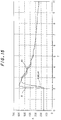
- the EGR control valve 122 when mounted on the engine, it will be possible to estimate the exhaust gas recirculation rate to a fair extent by detecting the amount of EGR control valve lifting and the ratio between the manifold pressure Pb (negative pressure) in the intake pipe 12 and the atmospheric pressure Pa, as illustrated in Figure 20.
- Pb negative pressure
- the exhaust gas flow rate characteristics change slightly with exhaust manifold pressure and exhaust gas temperature, the change can be absorbed by the ratio between the gas flow rates as explained later.
- the invention is based on this concept and estimates the EGR rate on the basis of the flow rate characteristics of the valve.
- valve opening area is detected through the valve lifting amount, this is because the EGR control valve 122 used here has a structure whose amount of lifting corresponds to the opening area. When another valve such as a linear solenoid is used, therefore, the valve opening area should be detected in a different manner.
- the EGR rate will be classified into two kinds of rates, i.e., one under a steady-state and another under a transient state.
- the steady-state is a condition in which the EGR operation is stable
- the transient state is a condition in which the EGR operation is being started or terminated so that the EGR operation is unstable.
- the EGR rate under a steady-state is considered to be a value where the amount of actual valve lifting is equal to the command value for the valve lifting amount.
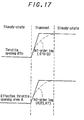
- the transient state is considered to be a condition in which the amount of actual valve lifting is not equal to the command value, as illustrated in Figure 21, so that the EGR rate deviates from the EGR rate under a steady-state (hereinafter referred to as "steady-state EGR rate) by an amount equal to the exhaust gas flow rate corresponding to the discrepancy in the actual amount and the command value, as illustrated in Figure 20.
- steady-state EGR rate the upstream pressure is indicated by the manifold pressure Pb and the downstream pressure by the atmospheric pressure Pa
- command value actual valve lifting amount
- gas flow rate corresponding to actual valve lifting amount/gas flow rate corresponding to command value 1.0
- net EGR rate (steady-state EGR rate) x (ratio between gas flow rates).
- the EGR rate is sometimes referred to as the "net" EGR rate.
- net EGR rate (steady-state EGR rate) x ⁇ (gas flow rate QACT determined by actual valve lifting amount and the ratio between upstream pressure and downstream pressure of the valve)/ (gas flow rate QCMD determined by command value and the ratio between upstream pressure and downstream pressure of the valve) ⁇
- the steady-state EGR rate and the correction coefficient under a steady-state are sometimes referred to as the "basic EGR rate” and “basic correction coefficient", respectively.
- the EGR rate is sometimes referred to as the "net EGR rate”.
- the correction coefficient under a steady-state KEGRMAP has been determined through experiments beforehand with respect to the engine speed Ne and the manifold pressure Pb and is prepared as mapped data as illustrated in Figure 22 such that the value can be retrieved based on the parameters.
- the EGR rate is used in various manners in references such as:
- the EGR rate is used in the specification mainly under the definition of 3). More concretely, the steady-state EGR rate is obtained by (1- coefficient KEGRMAP).
- the coefficient KEGRMAP is specifically determined as a value indicative of: fuel injection amount under EGR operation/fuel injection amount under no EGR operation
- the exhaust gas recirculation rate is determined by multiplying the basic EGR rate (the steady-state EGR rate) by the ratio between the gas flow rates as just mentioned before.
- the EGR rate is determined as a value relative to the basic EGR rate
- the EGR rate estimation system according to the invention will be applied to any EGR rate defined in 1) to 3) when the basic EGR rate is determined in the same manner.
- the EGR control is conducted by determining a command value of the EGR control valve lifting amount on the basis of the engine speed, manifold pressure, etc., as illustrated in Figure 21, and the actual behavior of the EGR control valve lags behind the time that the command value is issued. Namely, there is a response delay between the actual valve lifting and issuing the command value to do so. Moreover, it takes additional time for the exhaust gas passing through the valve to enter the combustion chamber.
- net EGR rate (steady-state EGR rate) x ⁇ (gas flow rate QACT determined by actual valve lifting amount and the ratio between upstream pressure and downstream pressure of the valve)/ (gas flow rate QCMD determined by command value and the ratio between upstream pressure and downstream pressure of the valve) ⁇
- the delay of the exhaust gas behavior was assumed to be a first-order lag.
- the dead time it can be considered that the exhaust gas passing through the valve is assumed to remain for a while in a space (chamber) before the combustion chamber and after a pause, i.e., the dead time, enters the combustion chamber at one time. Therefore, the net EGR rate is consecutively estimated and is stored in the memory each time the program is activated. And among the stored net EGR rates, one estimated at a previous control cycle corresponding to the delay time is selected and is deemed to be the true net EGR rate.
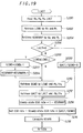
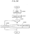
- the program begins at S200 in which the engine speed Ne, the manifold pressure Pb, the atmospheric pressure Pa, and the actual valve lifting amount named LACT (the output of the sensor 123) are read, and proceeds to S202 in which the command value for valve lifting amount LCMD is retrieved from mapped data using the engine speed Ne and the manifold pressure Pb as address data. Like the aforesaid correction coefficient, the mapped data for the command value LCMD is predetermined with respect to the same parameters as illustrated in Figure 23. The program then moves to S204 in which the basic EGR rate correction coefficient KEGRMAP is retrieved from the mapped data at least using the engine speed Ne and the manifold pressure Pb as illustrated in Figure 22.
- the program then advances to S206 in which it is confirmed that the actual valve lifting amount LACT is not zero, namely it is confirmed that the EGR control valve 122 is opened, and to S208 in which the retrieved command value LCMD is compared with a predetermined lower limit LCMDLL (a least value) to determine whether the retrieved command value is less than the lower limit.
- LCMDLL a least value
- the program proceeds to S210 in which the ratio Pb/Pa between the manifold pressure Pb and the atmospheric pressure Pa is calculated and using the calculated ratio and the retrieved command value LCMD, the gas flow rate QCMD corresponding thereto is retrieved from mapped data which has been prepared in advance on the basis of the characteristics illustrated in Figure 20.
- the gas flow rate is that mentioned in the equation as "gas flow rate QCMD determined by the command value and the ratio between upstream pressure and downstream pressure of the valve".
- the program then goes to S212 in which the gas flow rate QACT is retrieved from mapped data (whose characteristic is similar to that shown in Figure 20) prepared in advance. This corresponds to the term in the equation "gas flow rate QACT determined by actual valve lifting amount and the ratio between upstream pressure and downstream pressure of the valve".
- the program then proceeds to S214 in which the retrieved EGR rate correction coefficient KEGRMAP is subtracted from 1.0 and the difference resulting therefrom is deemed as the steady-state EGR rate (basic EGR rate or steady-state EGR rate).
- the steady-state EGR rate means the EGR rate under which EGR operation is in a stable state, i.e., the EGR operation is not under a transient condition, such as when the operation is being started or terminated.
- the program then moves to S216 in which the net exhaust gas recirculation rate is calculated by multiplying the steady-state EGR rate by the ratio QACT/QCMD, and to S218 in which a fuel injection correction coefficient KEGRN is calculated.
- Figure 24 is a flowchart showing the subroutine for calculating the coefficient KEGRN.
- the net EGR rate (that obtained at S216 of Figure 19) is subtracted from 1.0 and the difference resulting therefrom is deemed to be the fuel injection correction coefficient KEGRN.
- the program then proceeds to S302 in which the calculated coefficient KEGRN is stored in a ring buffer prepared in the ROM 74.
- Figure 25 shows the configuration of the ring buffer. As illustrated, the ring buffer has n addresses which are numbered from 1 to n and are so identified.
- the programs of the flowcharts of Figures 19 and 24 are activated at respective TDC positions and the fuel injection correction coefficient KEGRN is calculated, the calculated coefficient KEGRN is consecutively stored in the ring buffer from the top.
- the program then proceeds to S304 in which the delay time ⁇ is retrieved from mapped data using the engine speed Ne and the engine load such as the manifold pressure Pb as address data.
- Figure 26 shows the characteristics of the mapped data. Namely, the delay time ⁇ indicates a dead time during which the gas passing through the valve remains in the space before the combustion chamber. Since the dead time varies with engine operating conditions including the engine speed and the engine load, the delay time is set to vary with the parameters. Here, the delay time ⁇ is set as the ring buffer number.
- the program then moves to S306 in which one from among the stored fuel injection correction coefficients KEGRN corresponding to the retrieved delay time ⁇ (ring buffer number) is read and is determined to be the correction coefficient KEGRN at the current control cycle.
- the coefficient calculated 12 control cycles earlier is, for example, selected as the coefficient to be used in the current control cycle.
- the correction coefficient KEGRN corresponding to the EGR rate calculated 12 control cycles earlier was 1.0 and this means that the EGR control valve was closed.
- the value KEGRN then decreases gradually as 0.99, 0.98.., i.e., the EGR control valve was gradually driven in the opening direction and reaches the current position at the point A.
- the basic quantity of fuel injection TiM-F is multiplied by the correction coefficient KEGRN to decrease the same.
- the command value LCMD when the command value LCMD is less than the lower limit LCMDLL, the command value may occasionally be zero. If this happens, the gas flow rate QCMD retrieved at S210 becomes zero and as a result, division by zero would occur at the calculation in step S216, making the calculation impossible. Since, however, the previous value is kept in S222, the calculation can be successfully carried out in S216.
- the program then proceeds to S224 in which the basic correction coefficient KEGRMAPk-1 retrieved at the last control cycle is again used in the current control cycle.
- the basic EGR rate correction coefficient KEGRMAP retrieved in step S14 will be 1.0 based on the characteristics of the mapped data.
- the steady-state EGR rate is determined to be 0 in S204.
- the keeping of the last value in S224 aims to avoid this.
- the net EGR rate is consecutively estimated on the basis of the engine speed and engine load such as manifold pressure and based thereon the coefficient is consecutively calculated and stored at every control cycle.
- the delay time during which exhaust gas passed through the valve, but which remains before the combustion chamber is determined from the same parameters, and one from among the stored coefficients calculated at an earlier control cycle corresponding to the delay time is selected as the coefficient in the current control cycle.
- the dead time may be a fixed value. Since these are described in detail in Japanese Patent Application Hei 6(1994)-294,014 (filed in the United States on April 13, 1995 under the number of 08/421,182), no further explanation will here be made.
- the canister purging is conducted, in a program whose flowchart is not shown, such that a desired amount of canister purging is determined in response to the engine operating conditions such as engine speed and engine load in accordance with predetermined characteristics, and the aforesaid purge control valve 225 is regulated such that the desired amount of canister purging is achieved.
- the air/fuel ratio deviates to the rich side, since vapor gas having fuel is inducted in the air intake system. The deviation will be corrected in the feedback loop.
- the fuel injection quantity by the amount (named KPUG) corresponding to the purging fuel mass such that the amount of correction in the feedback system decreases, thereby reducing calculation load in the feedback loop and enhancing stability against disturbance and improving tracking performance.
- the correction will be made by calculating the quantity of fuel in the canister purged gas on the basis of the flow rate and HC concentration of the purged gas being inducted. Alternatively, it can be made by determining the correction coefficient KPUG corresponding to the purge mass from the difference of the LAF sensor output with respect to the desired air/fuel ratio. The latter method is used in the embodiment.
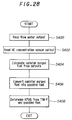
- Figure 28 is a flowchart showing the coefficient determination.
- the program starts at S400 in which the flow rate of purged gas is detected from the output of the aforesaid flow meter 226 and proceeds to S402 in which the HC concentration is detected from the output of the aforesaid HC concentration sensor, to S404 in which the quantity (mass) of fuel being inducted through canister purging is determined, to S406 in which the determined quantity of fuel is converted into the quantity of gasoline fuel.
- Most of the fuel component in the canister purged gas is butane, which is a light component of gasoline. Since the stoichiometric air/fuel ratio is different for butane and gasoline, the determined quantity is recalculated for the quantity of gasoline.
- the program then proceeds to S408 in which the basic quantity of fuel injection TiM-F obtained through map retrieval is multiplied by the desired air/fuel ratio to determine the amount of cylinder-inducted air Gc, and based on the value Gc and the converted quantity of gasoline fuel, the correction coefficient KPUG corresponding to purge mass is calculated. Needless to say, the correction coefficient KPUG will be 1.0 when the canister purging is not in effect.
- correction coefficient KPUG preestablish the correction coefficient KPUG, at 0.95 for example, in response to the desired amount of canister purging determined in the engine operating conditions and to regulate the purge control valve 225 in response to the correction coefficient.
- the correction coefficient KTOTAL is a general name that is the product of the various correction coefficients including KEGR and KPUG.
- the value additionally includes a correction coefficient KTW for coolant temperature and a correction coefficient KTA for intake air temperature, etc. Since, however, the nature of these corrections are well known, detailed explanation will be omitted.
- the desired air/fuel ratio KCMD and the desired air/fuel ratio correction coefficient KCMDM are determined or calculated.
- Figure 29 is a flowchart showing the determinations.
- the program begins at S500 in which the aforesaid base value KBS is determined. This is done by retrieving the mapped data (whose characteristics are shown in Figure 14) by the detected engine speed Ne and the manifold pressure Pb.
- the mapped data includes a base value at engine idling.
- the fuel metering control includes the lean burn control, i.e,, a lean mixture is supplied at a low engine load to improve fuel economy
- the mapped data will include that for lean burn control.
- the program then proceeds to S502 in which it is discriminated, by referring to a timer value, whether a lean burn control after engine starting is in effect to determine a lean correction coefficient.
- the system according to the invention is equipped with the variable timing mechanism 300 that allows the lean burn control after engine starting in which the desired air/fuel ratio is set to be leaner than the stoichiometric air/fuel ratio for a predetermined period after engine starting, while one intake valve is kept at rest in the period.
- the supplying of a rich mixture for a period after engine starting during which the catalyst remains inactivated would disadvantageously increase emission of HC in the exhaust gas.
- the lean burn control after engine starting can however avoid this problem.
- the program then proceeds to S504 in which it is discriminated whether the throttle opening is full-throttle (WOT) and calculates a full-throttle enrichment correction coefficient, to S506 in which it is discriminated whether the coolant temperature Tw is high and calculates an augmentative correction coefficient KTWOT.
- the value KTWOT includes a correction coefficient for protecting the engine at high coolant temperature.
- the program then proceeds to S508 in which the base value KBS is multiplied by the correction coefficients to correct the same and determines the desired air/fuel ratio KCMD.
- the program then goes to S510 in which the desired air/fuel ratio KCMD(k) is limited to a predetermined range, and to S512 in which it is discriminated whether the calculated desired air/fuel ratio KCMD(k) is 1.0 or thereabout.
- the program goes to S514 in which it is discriminated whether the O 2 sensor 56 is activated. This is conducted in a subroutine not shown by detecting the change in output voltage named VO 2 M of the O 2 sensor 56.
- the program then moves to S516 to calculate a value DKCMD for MIDO 2 control.
- This calculation means to make the desired air/fuel ratio variable for the LAF sensor 54 upstream of the O 2 sensor 56 provided downstream of the first catalytic converter 28 (in the case of the configuration illustrated in Figure 5, downstream of the first catalyst bed). More specifically, this is done by calculating the value from an error between a predetermined reference voltage VrefM and the O 2 sensor output voltage VO 2 M using PID control, as illustrated in Figure 7.
- the reference voltage VrefM is determined in response to the atmospheric pressure Pa, the coolant temperature Tw and the exhaust gas volume (which may be determined in response to the engine speed Ne and the manifold pressure Pb).
- the program then goes to S518 in which the calculated value DKCMD(k) is added to the desired air/fuel ratio to update it, to S520 in which a table (whose characteristic is shown in Figure 30) is looked up using the updated desired air/fuel ratio KCMD(k) as address data to retrieve a correction coefficient KETC. Since the charging efficiency of intake air varies with evaporation heat, this is done for compensating it. More specifically, the desired air/fuel ratio KCMD(k) is multiplied by the correction coefficient KETC as illustrated to determine the aforesaid desired air/fuel ratio correction coefficient KCMDM(k).
- the desired air/fuel ratio is expressed, in fact, by the equivalence ratio and the desired air/fuel ratio correction coefficient is determined by making the charging efficiency correction thereto.
- the program jumps to S520 since it is not necessary to conduct the MIDO 2 control.
- the program finally proceeds to S522 in which the desired air/fuel ratio correction coefficient KCMDM(k) is limited to a predetermined range.
- the basic quantity of fuel injection TiM-F is multiplied by the desired air/fuel ratio correction coefficient KCMDM and the other correction coefficient KTOTAL to determine the required quantity of fuel injection Tcyl.
- the feedback correction coefficients such as KSTR are calculated or determined.
- sampling of the LAF sensor outputs and the observer will be explained.
- the sampling block is illustrated as "Sel-V" in Figure 8.
- the detected air/fuel ratio also varies depending on the time required for the exhaust gas to reach the sensor and on the sensor response time (detection delay).
- the time required for the exhaust gas to reach the sensor in turn varies with the exhaust gas pressure, exhaust gas volume and the like. Since sampling synchronously with TDC means that the sampling is based on crank angle, moreover, the effect of engine speed is unavoidable. From this, it will be understood that air/fuel ratio detection is highly dependent on the engine operating condition.
- Figure 33 is a flowchart of the operations for sampling the LAF sensor. Since the accuracy of air/fuel ratio detection has a particularly close relationship with the estimation accuracy of the aforesaid observer, however, a brief explanation of the estimation of air/fuel ratio by the observer will be given before going into an explanation of this flowchart.
- Eq. 10 can be used to obtain the actual air/fuel ratio from the sensor output. That is to say, since Eq. 10 can be rewritten as Eq. 11, the value at time k-1 can be calculated back from the value at time k as shown by Eq. 12.
- A/F(k) ⁇ LAF(k+1)- ⁇ ⁇ LAF(k) ⁇ /(1- ⁇ ⁇ )
- A/F(k-1) ⁇ LAF(k)- ⁇ ⁇ LAF(k-1) ⁇ /(1- ⁇ ⁇ )
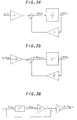
- FIG. 13 is a block diagram of the real-time A/F estimator.
- t(z) (1- ⁇ ⁇ )/(Z- ⁇ ⁇ )
- air/fuel ratio (or “fuel/air ratio”) used herein is the actual value corrected for the response delay calculated according to Eq. 13.)
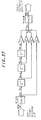
- the air/fuel ratio at the confluence point can be expressed as the sum of the products of the past firing histories of the respective cylinders and weighting coefficient Cn (for example, 40% for the cylinder that fired most recently, 30% for the one before that, and so on).
- This model can be represented as a block diagram as shown in Figure 37.
- Figure 38 relates to the case where fuel is supplied to three cylinders of a four-cylinder internal combustion engine so as to obtain an air/fuel ratio of 14.7 : 1, and to one cylinder so as to obtain an air/fuel ratio of 12.0 : 1.
- Figure 39 shows the air/fuel ratio at this time at the confluence point as obtained using the aforesaid model. While Figure 39 shows that a stepped output is obtained, when the response delay of the LAF sensor is taken into account, the sensor output becomes the smoothed wave designated "Model's output adjusted for delay" in Figure 40. The curve marked "Sensor's actual output” is based on the actually observed output of the LAF sensor under the same conditions. The close agreement of the model results with this verifies the validity of the model as a model of the exhaust system of a multiple cylinder internal combustion engine.
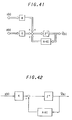
- Figure 41 shows the configuration of an ordinary observer. Since there is no input u(k) in the present model, however, the configuration has only y(k) as an input, as shown in Figure 42. This is expressed mathematically by Eq. 22.
- Figure 43 shows the aforesaid model and observer combined. As the results of the simulation are shown in the earlier application, they are omitted here. It suffices to say that this enables precise estimation of the air/fuel ratios at the individual cylinders from the air/fuel ratio at the confluence point.
- the air/fuel ratios of the individual cylinders can be separately controlled by PID control or the like.
- a confluence point feedback correction coefficient KLAF is calculated from the sensor output (confluence point air/fuel ratio) and the desired air/fuel ratio using the PID control law
- cylinder-by-cylinder feedback correction coefficients #nKLAF are calculated from the observer's estimated air/fuel ratio #nA/F.
- the cylinder-by-cylinder feedback correction coefficients #nKLAF are obtained by using the PID law to eliminate the error between the observer's estimated air/fuel ratio #nA/F and the desired value obtained by dividing the confluence point air/fuel ratio by the average value of the cylinder-by-cylinder feedback correction coefficients #nKLAF calculated in the preceding cycle.
- the subroutine of the flowchart of Figure 33 starts at S600 in which the engine speed Ne, the manifold pressure Pb and the valve timing V/T are read.
- the program then goes to S604 and S606 in which Hi and Lo valve timing maps (explained later) are looked up and to S608 in which the sensor output is sampled for use in observer computation at Hi or Lo valve timing.
- the timing map is looked up using the detected engine speed Ne and the manifold pressure Pb as address data, the No. of one of the aforesaid 12 buffers is selected, and the sampling value stored therein is selected.
- Figure 45 shows the characteristics of the timing maps. As shown, the characteristics are defined so that the sampling crank angle of the selected value becomes earlier with decreasing engine speed Ne and increasing manifold pressure (load) Pb. By an “earlier” value is meant a relatively older one sampled nearer to the preceding TDC. Conversely, the characteristics are defined so that the sampling crank angle of the selected value becomes later (becomes a newer value nearer to the following TDC) with increasing engine speed Ne and decreasing manifold pressure Pb.
- the program then goes to S610 in which the observer matrix is computed for HiV/T and to S612 in which the computation is similarly made for LoV/T. It then proceeds to S614 in which the valve timing is discriminated again and, depending on the result of the discrimination, to S616 in which the computation result for HiV/T is selected or to S618 in which that for LoV/T is selected. This completes the routine.
- the observer matrix has to be changed synchronously with switching of the valve timing.
- the estimation of the air/fuel ratios at the individual cylinders is not conducted instantaneously. Since several cycles are required for the observer computation to converge, the computations using the observer matrices before and after valve timing switchover are conducted in parallel and one of the computation results is selected in accordance with the new valve timing in S614, even when the valve timing is changed.
- the feedback correction coefficient is calculated for eliminating the error relative to the desired value and the quantity of fuel injection is determined.
- the aforesaid configuration improves the accuracy of the air/fuel ratio detection. Since, as shown in Figure 47, the sampling is conducted at relatively short intervals, the sampled values faithfully reflect the sensor output and the values sampled at relatively short intervals are progressively stored in the group of buffers. The inflection point of the sensor is predicted from the engine speed and the manifold pressure and the corresponding value is selected from the group of buffers at the prescribed crank angle. The observer computation is then conducted for estimating the air/fuel ratios at the individual cylinders, thereby enabling the cylinder-by-cylinder feedback control to be conducted as explained with reference to Figure 44.
- the CPU core 70 can therefore accurately ascertain the maximum and minimum values of the sensor output, as shown at the bottom of Figure 47.
- the estimation of the air/fuel ratios of the individual cylinders using the aforesaid observer can be conducted using values that approximate the behavior of the actual air/fuel ratio, thereby enabling an improvement in accuracy when the cylinder-by-cylinder air/fuel ratio feedback control is conducted in the manner described with reference to Figure 44.
- the sampling may be made for both the HiV/T and LoV/T, and then the discrimination may be made for the first time as to which timing is selected.
- the exhaust gas pressure drops due to decrease in atmospheric pressure at high altitude, the exhaust gas arrives at the LAF sensor in a time shorter than at a low altitude. As a result, it is preferable to select the datum sampled earlier as the altitude of the place where the vehicle travels increases.
- the feedback correction coefficient such as KSTR will then be explained.
- the PID control law is ordinarily used for fuel metering control for internal combustion engines.
- the control error between the desired value and the manipulated variable (control input) is multiplied by a P term (proportional term), an I term (integral term) and a D term (differential or derivative term) to obtain the feedback correction coefficient (feedback gain).
- P term proportional term
- I term integral term
- D term differential or derivative term
- the feedback correction coefficient KSTR is calculated using an adaptive controller (Self Tuning Regulator), instead of the confluence point feedback correction coefficient KLAF calculated using a PID controller as shown in Figure 44.
- This dynamically ensures the response of the system from the desired air/fuel ratio KCMD to the detected air/fuel ratio KACT, since the value KCMD becomes the smoothed value of KACT due to the engine response delay, if the basic quantity of fuel injection determined in the feedforward system is merely corrected by the desired air/fuel ratio feedback correction coefficient KCMDM.
- the correction coefficient KSTR is therefore multiplied by the basic quantity of fuel injection together with the correction coefficient KCMDM.
- the feedback correction coefficient is determined using modern control law such as adaptive control law, however, as the control response is relatively high in such cases, it may under some engine operating conditions become unstable owing to controlled variable fluctuation or oscillation, degrading the stability of control. Further, the supply of fuel is shut off during cruising and certain other operating conditions and, as shown in Figure 48, it is controlled in an open-loop (O/L) fashion during the fuel cutoff period.
- O/L open-loop
- the adaptive controller STR determines the feedback correction coefficient KSTR so as to immediately eliminate the error between the desired value and the detected value. As this difference is caused by the sensor detection delay and the like, however, the detected value does not indicate the true air/fuel ratio. Since the adaptive controller nevertheless absorbs the relatively large difference all at one time, KSTR fluctuates widely as shown in Figure 48, thereby also causing the controlled variable to fluctuate or oscillate and degrading the control stability.
- This problem is not limited to the time of resumption of fuel supply following cutoff. It also arises at the time of resuming feedback control following full-load enrichment and at resuming stoichiometric air/fuel ratio control following lean-burn control. It also occurs when switching from perturbation control in which the desired air/fuel ratio is deliberately fluctuated to control using a fixed desired air/fuel ratio. In other words, the problem arises whenever a large variation occurs in the desired air/fuel ratio.
- a control law such as the adaptive control law and another feedback correction coefficient of low control response using a control law such as the PID control law (illustrated as KLAF in the figure) and to select one or the other of the feedback correction coefficients depending on the engine operating condition. Since the different types of control laws have different characteristics, however, a sharp difference in level may arise between the two correction coefficients. Because of this, switching between the correction coefficients is liable to destabilize the controlled variable and degrade the control stability.
- the system according to the invention is configured such that the feedback correction coefficients different in control response are determined using an adaptive control law and a PID control law to be switched in response to the operating conditions of the engine and the switching between the feedback correction coefficients is smoothed, thereby improving fuel metering and air/fuel ratio control performance while ensuring control stability.
- Figure 49 is a subroutine flowchart showing the determination or calculation of the feedback correction coefficients including KSTR.
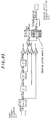
- the adaptive controller STR will first be explained with reference to Figure 50.
- the adaptive controller comprises a controller named STR (Self Tuning Regulator) and an adaptation mechanism (controller (system) parameter estimator).
- STR Self Tuning Regulator
- adaptation mechanism controller (system) parameter estimator
- the required quantity of fuel injection Tcyl is determined on the basis of the basic quantity of fuel injection in the feedforward system and based on the value Tcyl, the output quantity of fuel injection Tout is determined as will be explained later and is supplied to the controlled plant (engine 10) through fuel injector 22.
- the desired air/fuel ratio KCMD and the controlled variable (detected air/fuel ratio) KACT (plant output y) are input to the STR controller that calculates the feedback correction coefficient KSTR using a recursion or recurrence formula.
- the STR controller receives the coefficient vector (controller parameters expressed as a vector) ⁇ adaptively estimated or identified by the adaptation mechanism and forms a feedback compensator.
- One identification or adaptation law (algorithm) available for adaptive control is that proposed by I.D. Landau et al.
- the adaptive control system is nonlinear in characteristic so that a stability problem is inherent.
- the stability of the adaptation law expressed in a recursion formula is ensured at least using Lyapunov's theory or Popov's hyperstability theory. This method is described in, for example, Computrol (Corona Publishing Co., Ltd.) No. 27, pp. 28-41; Automatic Control Handbook (Ohm Publishing Co., Ltd.) pp. 703-707; "A Survey of Model Reference Adaptive Techniques - Theory and Applications" by I.D. Landau in Automatica , Vol.
- the adaptation or identification algorithm of I. D. Landau et al. is used in the present system.
- this adaptation or identification algorithm when the polynomials of the denominator and numerator of the transfer function B(Z -1 )/A(Z -1 ) of the discrete controlled system are defined in the manner of Eq. 25 and Eq. 26 shown below, then the controller parameters or system (adaptive) parameters ⁇ (k) are made up of parameters (dynamic engine characteristic parameters) as shown in Eq. 27 and are expressed as a vector (transpose vector). And the input zeta (k) to the adaptation mechanism becomes that shown by Eq. 28.
- the factors constituting the STR controller i.e., the scalar quantity b ⁇ o -1 (k) that determines the gain, the control factor B ⁇ R (Z -1 ,k) that uses the manipulated variable and ⁇ (Z -1 ,k) that uses the controlled variable, all shown in Eq. 27, are expressed respectively as Eq. 29 to Eq. 31.
- "m",”n" means the order of the numerator and denominator of the plant and "d” means the dead time.
- b ⁇ 0 -1 (k) 1/b 0
- the adaptation mechanism estimates or identifies each coefficient of the scalar quantity and control factors and supplies to the STR controller.
- the controller parameters when expressing the coefficients in a group by a vector ⁇ , is calculated by Eq. 32 below.
- ⁇ (k) is a gain matrix (the (m+n+d)th order square matrix) that determines the estimation/identification rate or speed of the controller parameters ⁇
- e asterisk (k) is a signal indicating the generalized estimation/identification error, i.e., an estimation error signal of the controlled parameters. They are represented by recursion formulas such as those of Eqs. 33 and 34.
- the adaptation mechanism estimates or identifies each of the controller parameters (vector) ⁇ using the manipulated variable u(i) and the controlled variable y (j) of the plant (i,j includes past values) such that an error between the desired value and the controlled variable becomes zero.
- Any of the algorithms are suitable for the time-varying plant such as the fuel metering control system according to the invention.
- ⁇ 3 (k) 1 - ⁇ k-1 ⁇ k-d ⁇ 2 ⁇ + ⁇ T k-d ⁇ k-1 ⁇ k-d ⁇ 1 tr ⁇ 0
- the adaptive controller is a controller expressed in a recursion formula such that the dynamic behavior of the controlled object (engine) can be ensured.
- the controller can be defined as the controller provided at its input with the adaptation mechanism (adaptation mechanism means), more precisely the adaptation mechanism, expressed in recursion formula.
- KSTR(k) KCMD k-d' -s 0 xy k -r 1 xKSTR k-1 -r 2 xKSTR k-2 -r 3 xKSTR k-3 b 0
- TTOTAL indicates the total value of the various corrections for atmospheric pressure, etc., conducted by addition terms (but does not include the injector dead time, etc., which is added separately at the time of outputting the output quantity of fuel injection Tout.)
- Figure 50 is, first, that the STR controller is placed outside the system for calculating the quantity of fuel injection (the aforesaid feedforward system), and not the quantity of fuel injection but the air/fuel ratio is defined as the desired value.
- the manipulated variable is indicated in terms of the quantity of fuel injection and the adaptation mechanism operates to determine the feedback correction coefficient KSTR so as to bring the air/fuel ratio produced as a result of fuel injection in the exhaust system to equal the desired value, thereby increasing robustness against disturbance.
- the adaptation mechanism operates to determine the feedback correction coefficient KSTR so as to bring the air/fuel ratio produced as a result of fuel injection in the exhaust system to equal the desired value, thereby increasing robustness against disturbance.
- a second characteristic feature is that the manipulated variable is determined as the product of the feedback correction coefficient and the basic quantity of fuel injection. This results in a marked improvement in the control convergence. On the other hand, the configuration has the drawback that the controlled value tends to fluctuate when the manipulated variable is inappropriately determined.
- a third characteristic feature is that, a conventional PID controller is provided, in addition to the STR controller, to determine another feedback correction coefficient named KLAF based on the PID control law, and either one is selected by a switch as the final feedback correction coefficient KFB.
- the detected value KACT(k) and the desired value KCMD(k) are also input to the PID controller, which calculates the PID correction coefficient KLAF(k) based on the PID control law so as to eliminate the control error between the detected value at the exhaust system confluence point and the desired value.
- the PID controller calculates the PID correction coefficient KLAF(k) based on the PID control law so as to eliminate the control error between the detected value at the exhaust system confluence point and the desired value.
- One or the other of the feedback correction coefficient KSTR, obtained by the adaptive control law, and the PID correction coefficient KLAF, obtained using the PID control law is selected to be used in determining the fuel injection calculation quantity by a switching mechanism shown in the figure.
- DKAF(k) KCMD(k-d') - KACT(k).
- KCMD(k-d') is the desired air/fuel ratio (in which d' indicates the dead time before KCMD is reflected in KACT and thus signifies the desired air/fuel ratio before the dead time control cycle)
- KACT(k) is the detected air/fuel ratio (in the current control (program) cycle).
- the P term is calculated by multiplying the error by the proportional gain KP
- the I term is calculated by adding the value of KLAFI(k-1), the feedback correction coefficient in the preceding control cycle (k-1), to the product of the error and the integral gain KI
- the D term is calculated by multiplying the difference between the value of DKAF(k), the error in the current control cycle (k), and the value of DKAF(k-1), the error in the preceding control cycle (k-1), by the differential gain KD.
- the gains KP, KI and KD are calculated based on the engine speed and the engine load. Specifically, they are retrieved from a map using the engine speed Ne and the manifold pressure Pb as address data.
- KLAF(k) the value of the feedback correction coefficient according to the PID control law in the current control cycle.
- the offset of 1.0 is assumed to be included in the I term KLAFI(k) so that the feedback correction coefficient is a multiplication coefficient (namely, the I term KLAFI(k) is given an initial value of 1.0).
- the STR controller holds the controller parameters such that the adaptive correction coefficient KSTR is 1.0 (initial value) or near one.
- the program starts at S700 in which the detected engine speed Ne and manifold pressure Pb, etc., are read, and proceeds to S704 in which a check is made as to whether the supply of fuel has been cut off.
- Fuel cutoff is implemented under specific engine operating conditions, such as when the throttle is fully closed and the engine speed is higher than a prescribed value, at which time the supply of fuel is stopped and open-loop control is effected.
- the program proceeds to S706 in which it is determined whether activation of the LAF sensor 54 is complete. This is done by comparing the difference between the output voltage and the center voltage of the LAF sensor 54 with a prescribed value (1.0 V, for example) and determining that activation is complete when the difference is smaller than the prescribed value.
- a prescribed value 1.0 V, for example
- the program goes to S710 in which it is checked whether the engine operating condition is in the feedback control region. This is conducted using a separate routine (not shown in the drawing). For example, when the engine operating condition has changed suddenly, such as during full-load enrichment, high engine speed, EGR or the like, fuel metering is controlled not in the closed-loop manner, but in an open-loop fashion.
- the program goes to S712 in which the output of the LAF sensor is read, to S714 in which the air/fuel ratio KACT(k) is determined or calculated from the output, and to S716 in which the feedback correction coefficient KFB (the general name for KSTR and KLAF) is calculated.
- KFB the general name for KSTR and KLAF
- S800 it is checked whether open-loop control was in effect during the preceding cycle (during the last control (calculation) cycle, namely, at the preceding routine activation time).
- the result in S800 is affirmative.
- a counter value C is reset to 0 in S102
- the bit of a flag FKSTR is reset to 0 in S804
- the feedback correction coefficient KFB is calculated in S106.
- the resetting of the bit of flag FKSTR to 0 in S804 indicates that the feedback correction coefficient is to be determined by the PID control law. Further, as explained hereafter, setting the bit of the flag FKSTR to 1 indicates that the feedback correction coefficient is to be determined by the adaptive control law.
- a subroutine showing the specific procedures for calculating the feedback correction coefficient KFB is shown by the flowchart of Figure 52.
- S900 it is checked whether the bit of flag FKSTR is set to 1, i.e., as to whether or not the operating condition is in the STR (controller) operation region. Since this flag was reset to 0 in S804 of the subroutine of Figure 51, the result in this step is NO and it is checked in S902 whether the bit of flag FKSTR was set to 1 in the preceding control cycle, i.e., as to whether or not the operating condition was in the STR (controller) operation region in the preceding cycle.
- the program advances to S816 in which it is checked whether the detected engine speed Ne is at or above a prescribed value NESTRLMT.
- the prescribed value NESTRLMT is set at a relatively high engine speed.
- the program proceeds to S818 in which a check is made which valve timing is selected in the variable valve timing mechanism. If HiV/T, the program proceeds to S804 where the PID correction coefficient is calculated. This is because the large amount of valve timing overlap present when the high-engine-speed side valve timing characteristic has been selected is apt to cause intake air blowby (escape of intake air through the exhaust valve), in which case the detected value KACT is not likely to be stable. In addition, the detection delay of the LAF sensor cannot be ignored during high-speed operation.
- the counter value C is compared with a predetermined value, 5 for example, in S824. So long as the counter value C is found to be at or below the predetermined value, the PID correction coefficient KLAF(k) calculated by PID control law is selected through the procedures of S804, S806, S900, S902 (S916), S904 and S908.
- the feedback correction coefficient is set to the value KLAF determined by the PID controller using PID control law.
- the PID correction coefficient KLAF according to PID control law does not absorb the control error DKAF between the desired value and the detected value all at one time but exhibits a relatively gradual absorption characteristic.
- the predetermined value is set to 5 (i.e., 5 control cycles or TDCs (TDC: Top Dead Center)) in this embodiment because this period is considered sufficient for absorbing the combustion delay and detection delay.
- the period (predetermined value) can be determined from the engine speed, engine load and other such factors affecting the exhaust gas transport delay parameters. For instance, the predetermined value can be set small when the engine speed and manifold pressure produce a small exhaust gas transport delay parameter and be set large when they produce a large exhaust gas transport delay parameter.
- the result of this check is YES, in which case the detected value KACT(k) is compared with a lower limit value a , e.g., 0.95, in S908. If the detected value is found to be equal to or greater than the lower limit value, the detected value is compared with an upper limit value b of, say, 1.05 in S910. When it is found to be equal to or smaller than the upper limit value, the program advances through S912 (explained later) to S914, where the adaptive correction coefficient KSTR(k) is calculated using the STR controller.
- a e.g. 0.95
- the program goes to S904 where the feedback correction coefficient is calculated based on PID control.
- a switch is made from PID control to STR (adaptive) control when the engine operating condition is in the STR controller operation region and the detected value KACT is 1 or in the vicinity thereof. This enables the switch from PID control to STR (adaptive) control to be made smoothly and prevents fluctuation of the controlled variable.
- the STR controller basically calculates the feedback correction coefficient KSTR(k) in accordance with Eq. 36 as explained earlier.
- the feedback correction coefficient KSTR is fixed at 1 and the STR controller operation is kept discontinued when feedback correction coefficient is determined by PID control.
- the scalar quantity b 0 (in the controller parameters that are held by the STR controller such that the adaptive correction coefficient KSTR is fixed at 1.0 (initial value) or thereabout) is divided by the value of the feedback correction coefficient by PID control in the preceding control cycle.
- the detected value KACT is 1 or near 1 in S908 and S910 and, in addition, the switch from PID control to STR control can be made smoothly.
- the feedback correction coefficient is determined based on PID control law for a predetermined period.
- the feedback correction coefficient determined by the STR controller is not used during periods when the difference between the detected air/fuel ratio and the true air/fuel ratio is large owing to the time required for the supplied fuel to be combusted and to the detection delay of the sensor itself.
- the controlled variable (detected value) therefore does not become unstable and degrade the stability of the control.
- control convergence can be improved after the detected value has stabilized by using the adaptive correction coefficient determined by the STR controller for operating the system so as to absorb the control error all at one time.
- a particularly notable feature of the embodiment is that an optimal balance is achieved between control stability and control convergence owing to the fact that the control convergence is improved by determining the manipulated variable as the product of the feedback correction coefficient and the manipulated variable.
- the feedback correction coefficient may be determined using the PID control law for a predetermined period after LAF sensor activation is completed.
- the feedback correction coefficient is determined based on PID control even after the passage of the predetermined period so that an optimal balance between control stability and convergence is achieved when feedback control is resumed following open loop control as at the time of discontinuing fuel cutoff, full-load enrichment or the like.
- the I term of KLAF is calculated using the feedback correction coefficient determined by the STR controller, while in resuming STR control following PID control a time at which the detected value KACT is 1 or near one is selected and the initial value of the feedback correction coefficient by the adaptive control law (STR controller) is set approximately equal to the PID correction coefficient by PID control law.
- the system ensures smooth transition back and forth between PID control and adaptive control. Since the manipulated variable therefore does not change suddenly, the controlled variable does not become unstable.
- Fuel adhesion correction of the output quantity of fuel injection Tout will now be explained.
- a fuel adhesion correction compensator is inserted in series that has a transfer function inverse to that of the plant.
- the fuel adhesion correction parameters are retrieved from mapped data that are prepared in advance corresponding to engine operating conditions such as coolant temperature Tw, engine speed Ne, manifold pressure Pb, etc.
- the program starts at S1000 in which the various parameters are read and proceeds to S1002 in which a direct ratio A and a take-off ratio B are determined.
- This is conducted by retrieval from mapped data (whose characteristics are shown in Figure 55) using the detected engine speed Ne and manifold pressure Pb as address data.
- the mapped data are established separately for the Hi V/T and Lo V/T characteristics of the variable valve timing characteristics and the retrieval is conducted by selecting either of the mapped data corresponding to the valve timing characteristics currently selected.
- a table (whose characteristic is illustrated in Figure 56) is looked up using the detected coolant temperature as an address datum to retrieve a correction coefficient KATW and KBTW.
- ratios A, B are multiplied by the coefficient KATW and KBTW and are corrected.
- other correction coefficients KA, KB are determined in response to the presence/absence of the EGR and canister purging operation and the desired air/fuel ratio KCMD, although the determination is not illustrated in the figure.
- the program proceeds to S1004 in which it is determined whether fuel supply is cut off and when the result is negative, to S1006 in which the output quantity of fuel injection Tout is corrected in the manner as illustrated to determine the output quantity of fuel injection for the individual cylinders Tout(n)-F.
- the program proceeds to S1008 in which the value Tout(n)-F is made zero.
- the value TWP(n) illustrated means the quantity of fuel adhered to the wall of the intake pipe 12.
- Figure 57 is a subroutine flowchart for determining or calculating the value TWP(n).
- the program illustrated is activated at a predetermined crank angular position.
- the program starts at S1100 in which it is determined whether the current program loop is within a period starting at a time when the Tout calculation begins and ending at a time when fuel injection at any cylinder ceases.
- the period is hereinafter referred to as "fuel metering control period”.
- the program proceeds to S1102 in which the bit of a first flag FCTWP(n) indicating the termination of the TWP(n)calculation for the cylinder n is set to 0 to permit the calculation and the program is immediately terminated.
- the value TWP(k-1) is a value calculated at the last control cycle.
- the first term in the right of the equation means the quantity of fuel that adhered to the wall at the last injection and still remains there without being taken off, and the second term thereof means the quantity of fuel that adheres to the wall at the current injection.
- the program then proceeds to S1112 in which the bit of a flag TTWPR(n) (indicating that the quantity of fuel adhesion is zero) is set to zero, to S1106 in which the bit of the first flag FCTWP(n) is set to 1 and then the program is terminated.
- TTWPR(n) indicating that the quantity of fuel adhesion is zero
- the program then proceeds to S1118 in which it is determined whether the value TWP(n) is greater than a predetermined small value TWPLG, and then to S1112 when affirmative. If negative, since this means that the remaining quantity of fuel adhesion is small enough to be ignored, the program goes to S1120 in which the value is set to zero, to S1122 in which the bit of the second flag is set to 1, and then to S1106.
- the third catalyst 94 is preferably a so-called “light-off” catalyzer that stimulates the activation of the catalysts in a shorter period, for example, one that is a so-called “electrically heated catalyzer” having a heater to promote activation. In that sense, the volume of the third catalyst should be sufficiently smaller than the catalysts installed downstream thereof.
- the third catalyst 94 may be a three-way catalyst similarly to the others.
- the third catalyst 94 may be provided when desired.
- the provision of the third catalyst 94 will be effective, since the volume or amount of the exhaust gas at each bank will be relatively small.
- the provision of the third catalyst would affect the dead time in the system and as a result, the controlled variable, etc., will be different.
- Figure 58 is a block diagram, similar to Figure 8, but showing the configuration of the system according to a second embodiment of the invention.
- a second O 2 sensor 98 is installed downstream of the second catalytic converter 30. Outputs of the second O 2 sensor 98 are used to correct the desired air/fuel ratio KCMD as illustrated.
- the desired air/fuel ratio KCMD can therefore be determined more optimally, enhancing control performance. Since the air/fuel ratio of the exhaust gas that will finally be emitted to the air is detected, emission efficiency will be improved.
- the configuration also makes it possible to monitor whether the catalysts positioned upstream of the O 2 sensor 98 degrade.
- the second O 2 sensor 98 may be used as a substitute for the first O 2 sensor 56.
- the second catalytic converter 30 may have the same configuration as is disclosed in Figure 5 and the second O 2 sensor may be placed at a position between catalyst beds.
- the second O 2 sensor 98 is followed by a low-pass filter 500 having the cut-off frequency of 1000 Hz. Since the filter 500 and the filter 60 do not have linear characteristics, they may be of the type called linearizer that can compensate the deficiency.
- throttle valve is operated by a stepper motor in the foregoing embodiments, it can instead be mechanically linked with the accelerator pedal and be directly operated in response to accelerator pedal depression.
- EGR control valve of a motor-powered type is used in the EGR mechanism, it is alternative possible to use that having a diaphragm operable by the vacuum pressure in the intake pipe.
- the second catalytic converter 30 may be omitted, although it depends on the performance of the first catalytic converter.
- the air/fuel ratio is, in fact, expressed as an equivalence ratio
- the air/fuel ratio and the equivalence ratio can instead be determined separately.
- MRACS model reference adaptive control systems
Applications Claiming Priority (2)
| Application Number | Priority Date | Filing Date | Title |
|---|---|---|---|
| JP34003494 | 1994-12-30 | ||
| JP340034/94 | 1994-12-30 |
Publications (2)
| Publication Number | Publication Date |
|---|---|
| EP0719926A2 true EP0719926A2 (de) | 1996-07-03 |
| EP0719926A3 EP0719926A3 (de) | 1999-03-03 |
Family
ID=18333112
Family Applications (1)
| Application Number | Title | Priority Date | Filing Date |
|---|---|---|---|
| EP96300012A Withdrawn EP0719926A3 (de) | 1994-12-30 | 1996-01-02 | Regelungssystem für die Brennstoffdosierung eines Innenverbrennungsmotors |
Country Status (2)
| Country | Link |
|---|---|
| US (1) | US5758308A (de) |
| EP (1) | EP0719926A3 (de) |
Cited By (4)
| Publication number | Priority date | Publication date | Assignee | Title |
|---|---|---|---|---|
| EP0844373A1 (de) * | 1996-11-20 | 1998-05-27 | Honda Giken Kogyo Kabushiki Kaisha | Reinigungsanlage der Verbrennungsgase eines internen Verbrennungsmotors |
| EP0943791A3 (de) * | 1998-03-18 | 2000-07-05 | Toyota Jidosha Kabushiki Kaisha | Vorrichtung zum Behandeln von Kraftstoffdampf eines Magermotors |
| FR2989119A1 (fr) * | 2012-04-05 | 2013-10-11 | Peugeot Citroen Automobiles Sa | Procede de commande d'une alimentation en carburant d'un moteur a combustion interne equipant un vehicule automobile |
| US20220268217A1 (en) * | 2019-07-03 | 2022-08-25 | Safran Aircraft Engines | Method for determining the density of fuel for metering fuel in a fuel supply circuit of an aircraft engine |
Families Citing this family (17)
| Publication number | Priority date | Publication date | Assignee | Title |
|---|---|---|---|---|
| JPH1073043A (ja) * | 1996-08-29 | 1998-03-17 | Honda Motor Co Ltd | 内燃機関の空燃比制御装置 |
| JP3218997B2 (ja) * | 1996-12-10 | 2001-10-15 | トヨタ自動車株式会社 | 内燃機関の負圧制御装置 |
| JPH10318015A (ja) * | 1997-05-20 | 1998-12-02 | Denso Corp | 内燃機関の空燃比制御装置 |
| JP3307858B2 (ja) * | 1997-08-22 | 2002-07-24 | 本田技研工業株式会社 | 内燃機関の蒸発燃料処理装置 |
| JPH11173185A (ja) * | 1997-12-10 | 1999-06-29 | Denso Corp | 内燃機関の燃料噴射制御装置 |
| JPH11351046A (ja) * | 1998-06-10 | 1999-12-21 | Honda Motor Co Ltd | 多気筒内燃エンジンの燃料噴射制御装置 |
| DE19830300C2 (de) | 1998-07-07 | 2000-05-18 | Bosch Gmbh Robert | Verfahren zum Betreiben einer Brennkraftmaschine insbesondere eines Kraftfahrzeugs |
| US6189378B1 (en) * | 1998-12-14 | 2001-02-20 | Caterpillar Inc. | Electronically controlled fuel injector trimming |
| JP3991809B2 (ja) * | 2002-08-01 | 2007-10-17 | トヨタ自動車株式会社 | 内燃機関の始動時燃料噴射装置 |
| DE10248633B4 (de) * | 2002-10-18 | 2006-01-12 | Mtu Friedrichshafen Gmbh | Verfahren zur Drehzahl-Regelung einer Antriebseinheit |
| US7010417B2 (en) * | 2002-12-03 | 2006-03-07 | Cummins, Inc. | System and method for determining maximum available engine torque |
| US6879903B2 (en) * | 2002-12-27 | 2005-04-12 | Caterpillar Inc | Method for estimating fuel injector performance |
| US6801847B2 (en) | 2002-12-27 | 2004-10-05 | Caterpillar Inc | Method for estimating fuel injector performance |
| JP4755155B2 (ja) * | 2007-08-30 | 2011-08-24 | 三菱重工業株式会社 | ガスエンジンの統合制御方法及び装置 |
| JP4685953B2 (ja) * | 2009-07-17 | 2011-05-18 | Dowaエレクトロニクス株式会社 | 横方向を電流導通方向とする電子デバイス用エピタキシャル基板およびその製造方法 |
| US20180058350A1 (en) * | 2016-08-31 | 2018-03-01 | GM Global Technology Operations LLC | Method and apparatus for controlling operation of an internal combustion engine |
| DE102017009583B3 (de) * | 2017-10-16 | 2018-11-22 | Mtu Friedrichshafen Gmbh | Verfahren zur modellbasierten Steuerung und Regelung einer Brennkraftmaschine |
Citations (5)
| Publication number | Priority date | Publication date | Assignee | Title |
|---|---|---|---|---|
| EP0416511A1 (de) * | 1989-09-04 | 1991-03-13 | Hitachi, Ltd. | Verfahren zur Kraftstoffeinspritzung für eine Brennkraftmaschine |
| EP0536001A1 (de) * | 1991-10-03 | 1993-04-07 | Honda Giken Kogyo Kabushiki Kaisha | Steuerungssystem für Verbrennungsmotoren |
| EP0582085A2 (de) * | 1992-07-03 | 1994-02-09 | Honda Giken Kogyo Kabushiki Kaisha | Brennstoffdosierungsteuersystem und Verfahren zum Schätzen des Zylinderluftstroms in Verbrennungsmotoren |
| EP0594114A2 (de) * | 1992-10-19 | 1994-04-27 | Honda Giken Kogyo Kabushiki Kaisha | Regelungssystem für die Brennstoffdosierung eines Innenverbrennungsmotors |
| EP0626511A2 (de) * | 1992-01-09 | 1994-11-30 | Honda Giken Kogyo Kabushiki Kaisha | Steuerungssystem für Verbrennungsmotoren |
Family Cites Families (22)
| Publication number | Priority date | Publication date | Assignee | Title |
|---|---|---|---|---|
| JPS57122144A (en) * | 1981-01-20 | 1982-07-29 | Nissan Motor Co Ltd | Air fuel ratio feedback control unit |
| JPS61244848A (ja) * | 1985-04-22 | 1986-10-31 | Nissan Motor Co Ltd | 空燃比制御装置 |
| DE3539395A1 (de) * | 1985-11-07 | 1987-05-14 | Bosch Gmbh Robert | Verfahren und einrichtung zur adaption der gemischsteuerung bei brennkraftmaschinen |
| JPS6453038A (en) * | 1987-08-18 | 1989-03-01 | Mitsubishi Motors Corp | Air-fuel ratio controller for internal combustion engine |
| JPH01313644A (ja) * | 1988-06-13 | 1989-12-19 | Toyota Motor Corp | 内燃機関制御装置用の酸素濃度検出装置 |
| JPH0267443A (ja) * | 1988-09-02 | 1990-03-07 | Mitsubishi Motors Corp | 空燃比制御装置 |
| JP2666081B2 (ja) * | 1989-04-18 | 1997-10-22 | 本田技研工業株式会社 | 内燃機関のノック制御装置 |
| JPH04321740A (ja) * | 1991-04-19 | 1992-11-11 | Mitsubishi Electric Corp | エンジンの空燃比制御装置 |
| JP2689364B2 (ja) * | 1992-07-03 | 1997-12-10 | 本田技研工業株式会社 | 内燃機関の燃料噴射量制御装置 |
| US5426938A (en) * | 1992-09-18 | 1995-06-27 | Honda Giken Kogyo Kabushiki Kaisha | Control system for internal combustion engines |
| JPH06159126A (ja) * | 1992-11-26 | 1994-06-07 | Honda Motor Co Ltd | 内燃エンジンの制御装置 |
| JPH06294014A (ja) * | 1993-04-05 | 1994-10-21 | Toray Ind Inc | 導電性繊維の製造方法 |
| US5520160A (en) * | 1993-08-26 | 1996-05-28 | Nippondenso Co., Ltd. | Fuel evaporative gas and air-fuel ratio control system |
| JP3162585B2 (ja) * | 1993-09-13 | 2001-05-08 | 本田技研工業株式会社 | 内燃機関の空燃比検出装置 |
| DE69408757T2 (de) * | 1993-09-13 | 1998-06-25 | Honda Motor Co Ltd | Luft-Kraftstoff-Verhältnis-Erfassungsvorrichtung für eine Brennkraftmaschine |
| JP3162553B2 (ja) * | 1993-09-13 | 2001-05-08 | 本田技研工業株式会社 | 内燃機関の空燃比フィードバック制御装置 |
| JP3233526B2 (ja) * | 1994-03-09 | 2001-11-26 | 本田技研工業株式会社 | 適応制御を用いたフィードバック制御装置 |
| JP3307770B2 (ja) * | 1994-04-14 | 2002-07-24 | 本田技研工業株式会社 | 内燃機関の排気還流率推定装置 |
| US5505174A (en) * | 1994-04-14 | 1996-04-09 | Honda Giken Kogyo Kabushiki Kaisha | EGR rate estimation system for internal combustion engine |
| JP3354304B2 (ja) * | 1994-07-29 | 2002-12-09 | 本田技研工業株式会社 | 内燃機関の燃料噴射制御装置 |
| US5590638A (en) * | 1994-10-20 | 1997-01-07 | Honda Giken Kogyo Kabushiki Kaisha | Fuel metering control system for internal combustion engine |
| DE69525142T2 (de) * | 1995-02-25 | 2002-06-06 | Honda Motor Co Ltd | Kraftstoffmesssteuerungssystem für eine Brennkraftmaschine |
-
1995
- 1995-12-29 US US08/580,632 patent/US5758308A/en not_active Expired - Lifetime
-
1996
- 1996-01-02 EP EP96300012A patent/EP0719926A3/de not_active Withdrawn
Patent Citations (5)
| Publication number | Priority date | Publication date | Assignee | Title |
|---|---|---|---|---|
| EP0416511A1 (de) * | 1989-09-04 | 1991-03-13 | Hitachi, Ltd. | Verfahren zur Kraftstoffeinspritzung für eine Brennkraftmaschine |
| EP0536001A1 (de) * | 1991-10-03 | 1993-04-07 | Honda Giken Kogyo Kabushiki Kaisha | Steuerungssystem für Verbrennungsmotoren |
| EP0626511A2 (de) * | 1992-01-09 | 1994-11-30 | Honda Giken Kogyo Kabushiki Kaisha | Steuerungssystem für Verbrennungsmotoren |
| EP0582085A2 (de) * | 1992-07-03 | 1994-02-09 | Honda Giken Kogyo Kabushiki Kaisha | Brennstoffdosierungsteuersystem und Verfahren zum Schätzen des Zylinderluftstroms in Verbrennungsmotoren |
| EP0594114A2 (de) * | 1992-10-19 | 1994-04-27 | Honda Giken Kogyo Kabushiki Kaisha | Regelungssystem für die Brennstoffdosierung eines Innenverbrennungsmotors |
Cited By (9)
| Publication number | Priority date | Publication date | Assignee | Title |
|---|---|---|---|---|
| EP0844373A1 (de) * | 1996-11-20 | 1998-05-27 | Honda Giken Kogyo Kabushiki Kaisha | Reinigungsanlage der Verbrennungsgase eines internen Verbrennungsmotors |
| US5946906A (en) * | 1996-11-20 | 1999-09-07 | Honda Giken Kogyo Kabushiki Kaisha | Exhaust gas purification system of internal combustion engine |
| USRE42056E1 (en) | 1996-11-20 | 2011-01-25 | Honda Giken Kogyo Kabushiki Kaisha | Exhaust gas purification system of internal combustion engine |
| USRE43588E1 (en) | 1996-11-20 | 2012-08-21 | Honda Giken Kogyo Kabushiki Kaisha | Exhaust gas purification system of internal combustion engine |
| EP0943791A3 (de) * | 1998-03-18 | 2000-07-05 | Toyota Jidosha Kabushiki Kaisha | Vorrichtung zum Behandeln von Kraftstoffdampf eines Magermotors |
| US6257209B1 (en) | 1998-03-18 | 2001-07-10 | Toyota Jidosha Kabushiki Kaisha | Evaporative fuel processing apparatus for lean-burn internal combustion engine |
| FR2989119A1 (fr) * | 2012-04-05 | 2013-10-11 | Peugeot Citroen Automobiles Sa | Procede de commande d'une alimentation en carburant d'un moteur a combustion interne equipant un vehicule automobile |
| US20220268217A1 (en) * | 2019-07-03 | 2022-08-25 | Safran Aircraft Engines | Method for determining the density of fuel for metering fuel in a fuel supply circuit of an aircraft engine |
| US11927141B2 (en) * | 2019-07-03 | 2024-03-12 | Safran Aircraft Engines | Method for determining the density of fuel for metering fuel in a fuel supply circuit of an aircraft engine |
Also Published As
| Publication number | Publication date |
|---|---|
| US5758308A (en) | 1998-05-26 |
| EP0719926A3 (de) | 1999-03-03 |
Similar Documents
| Publication | Publication Date | Title |
|---|---|---|
| EP0719930B1 (de) | Regelungssystem für die Brennstoffdosierung eines Innenverbrennungsmotors | |
| EP0719929B1 (de) | Regelungssystem für die Brennstoffdosierung eines Innenverbrennungsmotors | |
| EP0719922B1 (de) | Regelungssystem für die Brennstoffdosierung eines Innenverbrennungsmotors | |
| US5908463A (en) | Fuel metering control system for internal combustion engine | |
| EP0719925B1 (de) | Regelungssystem für die Brennstoffdosierung eines Innenverbrennungsmotors | |
| US5758308A (en) | Fuel metering control system for internal combustion engine | |
| US5636621A (en) | Fuel metering control system for internal combustion engine | |
| US5632261A (en) | Fuel metering control system for internal combustion engine | |
| EP0719927B1 (de) | Regelungssystem für die Brennstoffdosierung eines Innenverbrennungsmotors | |
| JP3217682B2 (ja) | 内燃機関の燃料噴射制御装置 | |
| US5590638A (en) | Fuel metering control system for internal combustion engine | |
| US5606959A (en) | Fuel metering control system for internal combustion engine | |
| EP0728932B1 (de) | Kraftstoffmesssteuerungssystem für eine Brennkraftmaschine | |
| US6041279A (en) | Fuel metering control system for internal combustion engine | |
| EP0719919B1 (de) | Regelungssystem für die Brennstoffdosierung eines Innenverbrennungsmotors | |
| EP0728928B1 (de) | Kraftstoffmesssteuerungssystem für eine Brennkraftmaschine | |
| US5787868A (en) | Fuel metering control system for internal combustion engine | |
| US5666934A (en) | Fuel metering control system for internal combustion engine | |
| JP3217683B2 (ja) | 内燃機関の燃料噴射制御装置 | |
| US5758630A (en) | Fuel metering control system for internal combustion engine | |
| JP3217689B2 (ja) | 内燃機関の燃料噴射制御装置 | |
| JP3217680B2 (ja) | 内燃機関の燃料噴射制御装置 | |
| EP0719923A2 (de) | Regelungssystem für die Brennstoffdosierung eines Innenverbrennungsmotors | |
| JP3217679B2 (ja) | 内燃機関の燃料噴射制御装置 | |
| EP0728931B1 (de) | Kraftstoffmesssteuerungssystem für eine Brennkraftmaschine |
Legal Events
| Date | Code | Title | Description |
|---|---|---|---|
| PUAI | Public reference made under article 153(3) epc to a published international application that has entered the european phase |
Free format text: ORIGINAL CODE: 0009012 |
|
| AK | Designated contracting states |
Kind code of ref document: A2 Designated state(s): DE FR GB |
|
| PUAL | Search report despatched |
Free format text: ORIGINAL CODE: 0009013 |
|
| AK | Designated contracting states |
Kind code of ref document: A3 Designated state(s): DE FR GB |
|
| 17P | Request for examination filed |
Effective date: 19990331 |
|
| 17Q | First examination report despatched |
Effective date: 20010319 |
|
| STAA | Information on the status of an ep patent application or granted ep patent |
Free format text: STATUS: THE APPLICATION IS DEEMED TO BE WITHDRAWN |
|
| 18D | Application deemed to be withdrawn |
Effective date: 20011002 |