EP0719480B1 - Method and apparatus for simulating interference received by subscribers in a spread spectrum communications system - Google Patents
Method and apparatus for simulating interference received by subscribers in a spread spectrum communications system Download PDFInfo
- Publication number
- EP0719480B1 EP0719480B1 EP95926700A EP95926700A EP0719480B1 EP 0719480 B1 EP0719480 B1 EP 0719480B1 EP 95926700 A EP95926700 A EP 95926700A EP 95926700 A EP95926700 A EP 95926700A EP 0719480 B1 EP0719480 B1 EP 0719480B1
- Authority
- EP
- European Patent Office
- Prior art keywords
- signal
- interference
- communication
- over
- signal energy
- Prior art date
- Legal status (The legal status is an assumption and is not a legal conclusion. Google has not performed a legal analysis and makes no representation as to the accuracy of the status listed.)
- Expired - Lifetime
Links
- 238000004891 communication Methods 0.000 title claims abstract description 85
- 238000000034 method Methods 0.000 title claims abstract description 48
- 238000001228 spectrum Methods 0.000 title claims abstract description 19
- 239000002131 composite material Substances 0.000 claims abstract description 37
- 230000008054 signal transmission Effects 0.000 claims abstract description 19
- 230000005540 biological transmission Effects 0.000 claims description 17
- 230000004044 response Effects 0.000 claims description 12
- 230000008569 process Effects 0.000 claims description 9
- 230000003595 spectral effect Effects 0.000 claims description 6
- 238000001914 filtration Methods 0.000 claims description 5
- 230000007274 generation of a signal involved in cell-cell signaling Effects 0.000 claims description 4
- 238000005314 correlation function Methods 0.000 claims description 2
- 238000007493 shaping process Methods 0.000 claims description 2
- 238000004088 simulation Methods 0.000 abstract description 25
- 230000001413 cellular effect Effects 0.000 abstract description 18
- 230000000694 effects Effects 0.000 description 10
- 239000011159 matrix material Substances 0.000 description 10
- 238000012360 testing method Methods 0.000 description 10
- 238000010586 diagram Methods 0.000 description 9
- 230000007704 transition Effects 0.000 description 7
- 230000014509 gene expression Effects 0.000 description 6
- 238000011156 evaluation Methods 0.000 description 5
- 239000000969 carrier Substances 0.000 description 4
- 238000012545 processing Methods 0.000 description 4
- 238000013459 approach Methods 0.000 description 3
- 230000008901 benefit Effects 0.000 description 3
- 238000012546 transfer Methods 0.000 description 3
- 238000006243 chemical reaction Methods 0.000 description 2
- 230000003750 conditioning effect Effects 0.000 description 2
- 230000001419 dependent effect Effects 0.000 description 2
- 238000013461 design Methods 0.000 description 2
- 230000003252 repetitive effect Effects 0.000 description 2
- 230000002194 synthesizing effect Effects 0.000 description 2
- 238000004040 coloring Methods 0.000 description 1
- 238000012937 correction Methods 0.000 description 1
- 230000007423 decrease Effects 0.000 description 1
- 230000003111 delayed effect Effects 0.000 description 1
- 238000001514 detection method Methods 0.000 description 1
- 230000001939 inductive effect Effects 0.000 description 1
- 238000007689 inspection Methods 0.000 description 1
- 238000010295 mobile communication Methods 0.000 description 1
- 238000012986 modification Methods 0.000 description 1
- 230000004048 modification Effects 0.000 description 1
- 239000013307 optical fiber Substances 0.000 description 1
- 230000009467 reduction Effects 0.000 description 1
- 238000005070 sampling Methods 0.000 description 1
- 230000007480 spreading Effects 0.000 description 1
- 238000006467 substitution reaction Methods 0.000 description 1
Images


Classifications
-
- H—ELECTRICITY
- H04—ELECTRIC COMMUNICATION TECHNIQUE
- H04B—TRANSMISSION
- H04B17/00—Monitoring; Testing
-
- H—ELECTRICITY
- H04—ELECTRIC COMMUNICATION TECHNIQUE
- H04W—WIRELESS COMMUNICATION NETWORKS
- H04W52/00—Power management, e.g. Transmission Power Control [TPC] or power classes
- H04W52/04—Transmission power control [TPC]
- H04W52/18—TPC being performed according to specific parameters
- H04W52/26—TPC being performed according to specific parameters using transmission rate or quality of service QoS [Quality of Service]
- H04W52/267—TPC being performed according to specific parameters using transmission rate or quality of service QoS [Quality of Service] taking into account the information rate
-
- H—ELECTRICITY
- H04—ELECTRIC COMMUNICATION TECHNIQUE
- H04B—TRANSMISSION
- H04B17/00—Monitoring; Testing
- H04B17/30—Monitoring; Testing of propagation channels
- H04B17/391—Modelling the propagation channel
- H04B17/3912—Simulation models, e.g. distribution of spectral power density or received signal strength indicator [RSSI] for a given geographic region
-
- H—ELECTRICITY
- H04—ELECTRIC COMMUNICATION TECHNIQUE
- H04B—TRANSMISSION
- H04B7/00—Radio transmission systems, i.e. using radiation field
- H04B7/24—Radio transmission systems, i.e. using radiation field for communication between two or more posts
- H04B7/26—Radio transmission systems, i.e. using radiation field for communication between two or more posts at least one of which is mobile
- H04B7/2628—Radio transmission systems, i.e. using radiation field for communication between two or more posts at least one of which is mobile using code-division multiple access [CDMA] or spread spectrum multiple access [SSMA]
Definitions
- This invention relates generally to wireless communication networks such as, for example, cellular wireless local telephone systems and personal communication systems. More specifically, this invention relates to a novel and improved system and method for communicating information, in mobile cellular or satellite telephone systems, using spread spectrum type communication signals.
- CDMA code division multiple access
- TDMA time division multiple access
- FDMA frequency division multiple access
- AM modulation schemes such as amplitude companded single sideband
- CDMA spread spectrum modulation techniques have significant advantages over other modulation techniques for multiple access communication systems.
- the use of CDMA techniques in a multiple access communication system is disclosed in U. S. Pat. No. 4,901,307, issued February 13, 1990, entitled "SPREAD SPECTRUM MULTIPLE ACCESS COMMUNICATION SYSTEM USING SATELLITE OR TERRESTRIAL REPEATERS", and is assigned to the assignee of this invention.
- the CDMA techniques as disclosed in U. S. Pat. No. 4,901,307 contemplate the use of relatively long high speed pseudonoise (PN) sequences with each user channel being assigned a different PN sequence.
- PN pseudonoise
- the cross-correlation between different PN sequences and the autocorrelation of a PN sequence for all time shifts other than zero both have average values close to zero. In this way signals transmitted from a base station over a "forward" communication link are capable of being discriminated between upon reception by remote user or subscriber units.
- a preferred waveform implemented involves using a direct sequence PN spread spectrum carrier.
- the chip rate of the PN carrier was chosen to be 1.2288 MHz in the preferred embodiment.
- One consideration involved in the choice of chip rate is that it be exactly divisible by baseband data rates to be used in the communication system. It is also desirable for the chip rate to be a power of two times the baseband data rate.
- the baseband data rate is 9600 bits per second, leading to a choice of 1.2288 MHz, which is 128 (2 7 ) times 9600 for the PN chip rate.
- the code sequences used for spreading the spectrum are constructed from two different types of sequences, each with different properties to provide different functions.
- the outer code is also used to discriminate between signals transmitted by different cells or sectors to the mobile units.
- Implementation of a cellular CDMA system capable of providing adequate service to a particular geographic region generally involves consideration of a number of factors bearing upon system performance. For example, it is generally necessary to consider the extent of the available frequency spectrum, as well as the potential for coordination with other nearby communication systems. In addition, constraints imposed by thermal noise and interference generated by the various remote users or subscriber units needs to be taken into consideration. Estimates of interference are of particular concern within CDMA systems, since power is transmitted by the subscriber units over the same bandwidth irrespective of location within the cellular coverage area.
- Interference on a forward, i.e., cell-to-subscriber, link can occur when base stations within neighboring cells use the same or an adjacent CDMA communication or radio channel as that intended for reception by a particular subscriber unit.
- a selected number of subscriber units may be deployed at various distances from multiple base stations as a means of estimating forward link interference levels.
- attempting to determine forward link interference through such field tests requires the availability of many multiple subscriber units and base stations. This would preclude complete system calibration when the number of base stations available during initial system testing was less than the number to eventually be installed.
- EP 0 044 133 discloses a simulated interference system wherein an interference signal of an interference source is simulated by a narrow band coded control signal that is transmitted from a control transmitter to a target receiver that is engaged in normal communications.
- the control signal is received by the target receiver and is applied to an interference injector that is coupled to the antenna of the receiver.
- the interference injector decodes the control signal and couples a corresponding interference signal to the antenna of the receiver.
- the interference signal of the interference injector operates to disrupt the normal communications signals that are received by the target receiver.
- the system has the advantage that it affects only the equipment under test and does not substantially interfere with communication between nontest transmitters and receivers.
- the present invention provides a method and apparatus for simulating signal interference arising within a communication system such as a wireless subscriber telephone and/or data system.
- the communication system is preferably a type in which remote users or subscribers from a plurality of cells communicate information signals between one another or to public switched telephone networks using at least a one base station and code division multiple access (CDMA) spread spectrum type communication signals.
- the base station has at least one transmitter from which information is transmitted to subscriber units over at least one communication channel and is located in a first of the cells.
- the inventive method for simulating signal interference in the at least one communication channel includes the step of determining a first composite signal energy associated with signal transmission from the base station transmitter over a first set of simulated communication channels. A determination is also made as to a first average data rate for transmission of the first composite signal energy, which can be based on a rate established for various users within the system. Signal power transmitted over the one communication channel is adjusted in accordance with a first interference signal which is provided at a power level determined on the basis of the first composite signal energy and average data rate. The first interference signal is transmitted over the at least one communication channel.
- a determination of signal energy transmitted over the equivalent number of channels and associated average data rate are then used to determine the composite signal energy.
- the real remote users can be monitored to determine both the number of channels in use and either actual interference or volume of communication traffic.
- the present invention also contemplates determining a second composite signal energy for signal transmissions over a second set of simulated channels. A similar determination is made of a second average data rate at which this signal energy is transmitted in the second set of simulated channels. This allows generation of a second interference signal based on the second composite signal energy and average data rate. The second interference signal can be used to modify the first.
- the first interference signal represents an orthogonal interference component associated with signal transmission inside the first cell while the second interference signal represents a non-orthogonal interference component associated with signal transmission outside of the first cell.
- the power of signal energy transmitted over the first communication channel is adjusted in accordance with the orthogonal and non-orthogonal signal energies.
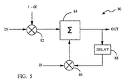
- the first interference signal is typically provided by generating a sequence of random variables and then shaping their spectrum by filtering them in accordance with a predetermined correlation function.
- the sequence of random variables can be scaled based on the first average data rate, and shifted based on a magnitude of the first composite signal energy. In a preferred embodiment this is accomplished by synthesizing electrical noise over a predetermined frequency band, preferably having a relatively uniform spectral density, and then adjusting the energy level of this electrical noise in response to the value of the first composite signal energy and average data rate.
- the signal energy can also be adjusted in response to the second composite signal energy and average data rate for other simulated channels.
- the invention further provides a technique for utilizing a random variable sequence, such as a Gaussian random variable, to model variations in the first composite signal.
- the apparatus for simulating signal interference between communication channels in the communication system generally has an energy selection element which outputs the first composite signal energy for signals transmitted over the first set of a desired number of simulated channels and a data rate generation element that outputs the first average data rate.
- a first interference signal generator coupled to the both the energy selector and data rate generator produces an output signal having a signal power based on the first composite signal power and average data rate.
- a preferred first interference signal generator uses at least one electrical noise signal generator with an output energy that is adjustable in response to a control signal input.
- At least one noise intensity controller coupled to the control input of the noise source generator, and itself having inputs coupled to the energy selector and data rate generator, provides a control signal having a value that varies in response to changes in the signal energy and data rate for simulated channels.
- At least a second energy selector can also be used which outputs a second composite signal energy for signals transmitted by a second set of simulated channels, and the noise intensity controller is configured to also base signal generation in part on the signal power which is transmitted by these other simulated channels.
- the controller has an element for generating a sequence of random variables, and means for scaling this sequence based on the average data rate.
- the controller also comprises means for shifting the sequence of random variables based on a magnitude of the first composite signal energy.
- the noise controller uses binary sequence generators to produce Gaussian random variables at preselected rates and sequence filters connected to receive and filter these binary sequences based on an estimated correlation time of data signals carried by the transmitted signal energy and on an average energy fluctuation. In either case the filtered electronic noise is transferred over said one communication channel.
- each cell-site or base station has several modulator-demodulator units or spread spectrum modems.
- Each modem consists of a digital spread spectrum transmit modulator, at least one digital spread spectrum data receiver and a searcher receiver.
- Each modem at a cell-site is assigned to a subscriber unit as needed to facilitate communication over a forward "traffic channel" with the assigned subscriber unit.
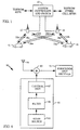
- FIG. 1 An exemplary cellular telephone system, in which the noise interference simulation system of the present invention may be integrated is illustrated in Figure 1.
- the system illustrated in Figure 1 utilizes spread spectrum modulation techniques in communication over forward traffic channels between cell-sites and system subscriber units or mobile telephones.
- Cellular systems in large cities may have hundreds of cell-site base stations serving hundreds of thousands of mobile telephones or other subscriber units.
- the use of spread spectrum techniques, in particular CDMA readily facilitates increases in user capacity in systems of this size as compared to conventional FM modulation type cellular systems.
- CDMA Code Division Multiple Access
- the present invention is described herein with reference to the mobile cellular system of Figure 1, it is understood that the teachings of the invention are equally applicable to CDMA communications systems in which a plurality of subscriber units are dispersed over a set of fixed locations.
- the present invention provides a method and apparatus for simulating the effect of signal interference received by a given subscriber unit due to data transmission on traffic channels within its own cell, as well that due to interference from signal transmission on traffic channels in surrounding cells.
- traffic channel interference is simulated by injecting random data into the signal transmitted by the cell-site base station located within the cell of a given subscriber unit. This enables simulation of interference arising from signal transmission on a selected number of traffic channels, irrespective of the number of traffic channels:
- the simulated traffic channel interference noise is transmitted by the cell-site within the simulated cell
- an analogous interference signal is directly injected into the receiver of the subscriber unit under test.
- the injected signal is formulated so as to account for the effects of propagation over the transmission path between the cell-site and the subscriber unit under test.
- system controller and switch 10 also referred to as a mobile telephone switching office (MTSO), typically includes interface and processing circuitry for providing system control to the cell-sites.
- Controller 10 also controls the routing of telephone calls from a public switched telephone network (PSTN) to an appropriate cell-site for transmission to an appropriate mobile or subscriber unit.
- PSTN public switched telephone network
- Controller 10 also controls the routing of calls from the mobile or remote subscriber units, using at least one cell-site, to the PSTN.
- Controller 10 may connect or link calls between subscriber users using the appropriate base stations since the subscriber units do not typically communicate directly with one another.
- Controller 10 may be coupled to the cell-sites by various means such as dedicated telephone lines, optical fiber links, or microwave communication links.
- FIG 1 two such exemplary cell-sites 12 and 14 are shown along with mobile units 16 and 18, where each mobile unit includes a cellular telephone.
- Exemplary cell-sites 12 and 14, as discussed herein and as illustrated in the drawings, are considered as providing service to an entire cell.
- a cell may be geographically divided into sectors with each sector providing service to a different coverage area. Accordingly, handoffs are generally required to be made between sectors within a cell, while diversity may also be achieved between sectors as is done between cells.
- lines 20a-20b and 22a-22b correspond to signal transmission, which includes data transmission over various traffic channels, between cell-site 12 and mobile units 16 and 18, respectively.
- lines 24a-24b and 26a-26b represent communication between cell-site 14 and mobile units 18 and 16, respectively.
- Cell-sites 12 and 14 nominally transmit using equal power.
- the coverage of cell-site service areas or cells is designed or laid out in geographic shapes such that the mobile units will normally be closest to one cell-site, and within only one sector if cell is divided into sectors.
- the mobile unit When the mobile unit is idle, i.e. no calls in progress, the mobile unit constantly monitors pilot signal transmissions from each nearby cell-site, and, if applicable, from a single cell-site if the cell is sectorized.
- Mobile unit 16 can determine which cell it is in by comparing signal strength for pilot signals transmitted from cell-sites 12 and 14.
- mobile unit 16 may be considered closest to cell-site 12.
- a control message is transmitted to the nearest cell-site, here cell-site 12.
- Cell-site 12 upon receiving the call request message, transfers the called number to system controller 10.
- System controller 10 then connects the call through the PSTN to the intended recipient.
- controller 10 transmits the call information to all of the cell-sites in the area.
- the cell-sites in return transmit a paging message within each respective coverage area that is intended for the called recipient mobile user.
- the intended recipient mobile unit When the intended recipient mobile unit "hears" or receives the page message, it responds with a control message that is transmitted to the nearest cell-site.
- This control message signals the system controller that this particular cell-site is in communication with the paged mobile unit. Controller 10 then routes the call through this cell-site to the mobile unit. Should mobile unit 16 move out of the coverage area of the initial cell-site, 12, an attempt is made to continue the call by routing the call through another cell-site.
- orthogonal Walsh functions are assigned to user channels on the cell-to-subscriber link.
- the digital symbol stream for each voice signal is multiplied by its assigned Walsh sequence.
- the Walsh coded symbol stream for each voice channel is then multiplied by the outer PN coded waveform.
- the resultant spread symbol streams are then added together to form a composite waveform.
- the resulting composite waveform is then modulated onto a sinusoidal carrier, bandpass filtered, translated to the desired operating frequency, amplified and radiated by the antenna system.
- Alternate embodiments of the present invention may interchange the order of some of the operations just described for forming the cell-site transmitted signal. For example, it may be preferred to multiply each voice channel by the outer PN coded waveform and perform the filter operation prior to summation of all the channel signals which are to be radiated by the antenna. It is well known in the art that the order of linear operations may be interchanged to obtain various implementation advantages and different designs.
- the waveform design of the preferred embodiment for cellular service uses the pilot carrier approach for the cell-to-subscriber link, as is described in U. S. Pat. No. 4,901,307. All cells transmit a pilot carrier using the same 32,768 length sequence, but with different timing offsets to prevent mutual interference.
- the symbol stream for a particular cellular user is combined in a first exclusive OR operation with the Walsh sequence assigned to that user.
- the Walsh function is typically clocked at a rate of 1.2288 MHz, while in an exemplary variable data rate system including voice, facsimile (FAX), and high/low-speed data channels the information symbol rate may vary from approximately 75 Hz to 76,800 Hz.
- the resulting coded waveform is combined in a second exclusive OR operation with a binary PN sequence also clocked at 1.2288 MHz.
- An identical binary PN sequence is used to encode each subscriber channel within a particular sector of the coverage area of the cellular system.
- each sequence may be used to process user data on a single RF channel associated with such a sector without inducing interference among the users within the sector.
- the signals carried by each channel may also be convolutional encoded, with repetition, and interleaved in order to provide error detection and correction functions which allow the system to operate at a much lower signal-to-noise and interference ratio.
- Techniques for convolutional encoding, repetition, and interleaving are well known in the art.
- the resulting signals are then generally modulated onto an RF carrier and summed with the pilot and setup carriers, along with the other voice carriers. Summation may be accomplished at several different points in the processing such as at the IF frequency, or at the baseband frequency either before or after multiplication by the PN sequence associated with the channels within a particular cell.
- Each voice carrier may also be multiplied by a value that sets its transmitted power relative to the power of the other voice carriers.
- This power control feature allows power to be allocated to those links that require higher power due to the intended recipient being in a relatively unfavorable location. Means are provided for the subscribers to report their received signal-to-noise ratio to allow the power to be set at a level that provides for adequate performance without wasting power. The orthogonality property of the Walsh functions is not disturbed by using different power levels for the different voice carriers provided that time alignment is maintained.
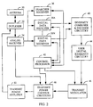
- FIG. 2 illustrates, in block diagram form, an exemplary embodiment of a subscriber unit transceiver.
- the receiver portion of the subscriber unit of Figure 2 comprises an analog receiver 34, a searcher receiver 36, several RAKE or digital data receivers 38A - 38N, and diversity combiner and decoder circuitry 40.
- the transmitter portion comprises transmit modulator 46, transmit power control circuitry 48, and transmit power amplifier 50. Shared between the receiver portion and the transmitter portion is an antenna 30, a duplexer 32, control processor 42, and user digital baseband circuitry 44.
- Control processor 42 is coupled to searcher receiver 36 and data receivers 38A - 38N in the receiver portion, and transmit modulator 46 and transmit power control circuitry 48 in the transmitter portion.
- User digital baseband circuitry 44 performs various functions such as analog-to-digital conversion and digital conversion, along with providing an interface to the subscriber unit microphone and speaker (not shown).
- Control processor 42 provides among other operations, functions such as signal processing; timing signal generation; power control; and control over handoff, diversity, and symbol combining. Further details of the operation of such a subscriber unit are provided in U. S. Patent No. 5,103,459.
- this interference includes interference due to transmission over various other traffic channels within the simulated cell, as well as over other pilot, sync or synchronization, and paging channels associated with subscribers within the simulated cell. Since in the exemplary system the signals transmitted over these channels are orthogonal to transmissions over the selected traffic channel under test, this interference is hereafter referred to as the orthogonal interference component.
- the subscriber unit also experiences interference due to signal transmission over channels in neighboring cells not orthogonal to the traffic channels within the simulated cell. Hence, interference due to signal transmission within surrounding cells is referred to as the non-orthogonal interference component.
- the power transmitted over the cell-to-subscriber link within an exemplary CDMA system is shared by pilot, sync, paging, and traffic (i.e., data) channels.
- the share of power allocated to each channel is varied based on the location of the associated subscriber unit, and in accordance with the aggregate number of subscriber units (i.e., the system load) in the communication system.
- Power is allocated among traffic channels by a controller within the cell-site transmitter of the simulated cell using digital adjustment of the gain associated with each channel.
- the gain of each channel within the exemplary system is typically represented by an unsigned 7-bit gain coefficient used to regulate the magnitude of both the in-phase (I) and quadrature phase (Q) channel components.
- the signal interference on the forward traffic, i.e., data, channel of a particular cell-to-subscriber link includes a pair of uncorrelated components: namely, an orthogonal component due to interference noise arising from transmissions to other subscribers within the simulated cell, and a non-orthogonal component due to interference from surrounding cells.
- a hexagonally partitioned region is shown corresponding to a coverage area for an exemplary multiple access communication system.
- the coverage area includes a plurality of hexagonal cells, labeled or numbered as C1-C36, surrounding a simulated cell C0, which is shown in greater detail in Figure 3B.
- a fixed or mobile subscriber S0 is positioned within cell C0 which is surrounded by a first tier of cells C1 to C6 ( Figure 3A), which is in turn surrounded by a second tier of cells C7 to C18, and so on.
- a cell-site transmitter (not shown) is positioned within the center of each hexagonal cell and is assumed to be equipped with an omni-directional antenna. Outside the hexagonal cell serviced by each transmitter, large-scale variation in the signal energy transmitted by each transmitter can be represented by a log-normally distributed random variable.
- x 3 R
- y 2 3
- the composite interference power T t arising at the subscriber unit S0 due to signal transmissions from cell-sites within the first three tiers is defined according to: where it is assumed that ⁇ is set equal to 4 in expression (1).
- the interference from cells in the third tier, i.e., T 3 may be expressed as:
- FIG. 4 there is shown a graphical representation of the interference (dB) from the third-tier cells relative to the total interference (T 3 /T t ), as a function of the angle ⁇ .
- subscriber unit S0 is seen to be located proximate the boundary of cell C1.
- the interference to which subscriber unit S0 is exposed may be viewed as arising from the following three sources:
- I oc k 2 ( I 1 (r, ⁇ ) + I 2 (r, ⁇ ) + I 3 (r, ⁇ ) + I 4 (r, ⁇ )) where k 2 is a proportionality constant.
- an interference signal based on the normalized non-orthogonal interference component specified by equation (19) is injected into the signal produced by the base station transmitter servicing the cell of the subscriber unit under evaluation.
- a non-orthogonal interference signal is created by passing white Gaussian noise through a set of attenuators and a fader. The attenuators are adjusted to simulate the propagation losses occurring over a particular transmission path, while the fader enables the simulation of small-scale fluctuations in interference level.
- non-orthogonal interference component is simulated in the preferred embodiment in accordance with the procedure NON-ORTHOGONAL INTERFERENCE SIMULATION set forth below.
- the power transmitted by each cell-site or cell base station is shared among pilot, sync, paging, and traffic channels.
- the share of power allocated to the traffic channel associated with a given cell-to-subscriber link may be varied in accordance with the location of the subscriber unit and the system load.
- Power is allocated among the traffic channels supported by the cell-site transmitter of the simulated cell through digital adjustment of the gain associated with each channel.
- the gain of each channel within the exemplary system will typically be represented by an unsigned 7-bit gain coefficient used to regulate the magnitude of both the in-phase (I) and quadrature phase (Q) channel components.
- the power levels associated with each traffic channel are dependent not only on the values of the corresponding digital gains, but also on the data rate of each. Specifically, the energy per code symbol (E S ) is proportional to r i , where r i denotes the normalized data rate.
- the orthogonal interference component is made to be orthogonal to the other channels actually supported by the cell-site. Included among these other channels are pilot, sync, and paging channels, as well as N r "real" traffic channels allocated to users physically present within the simulated cell.
- the orthogonal component of power S transmitted over the radio or communication channel is adjusted by a cell controller on the basis of the digital gain factor and an equivalent data rate r eq corresponding to an average of the data rates of a set of simulated traffic channels. More specifically, the orthogonal component of power S radiated over the radio channel is designed to simulate the transmission of N s simulated traffic channels at the equivalent rate r eq .
- equivalent rate r eq is determined using a sixteen-state, second order Markov model.
- Each state within the model is defined by the speech rates (e.g., full-rate, half-rate, quarter-rate or eighth-rate) associated with a pair of consecutive speech frames.
- state "0" corresponds to a pair of consecutive frames characterized by full-rate speech activity.
- Table I below sets forth the rates of speech activity for the pair of speech frames associated with each of sixteen Markov states.
- the probability of the occurrence of a given speech rate within a Frame (N+1) may be determined based on the rates indicated by the states of preceding Frames (N) and (N-1). Referring below to the first entry within Table II, there exists a probability of 0.911 that full-rate speech will exist in Frame (N+1) in the situation where both Frames (N) and (N-1) are at full rate and the Markov chain is set at state "0". The remainder of Table II gives the probabilities of transitioning to the indicated speech rate in Frame (N+1) for the other possible pairs of Markov states associated with Frame (N) and Frame (N-1).
- Table III shows the resulting first-order Markov steady-state probabilities for the existence of each of the four speech rates, i.e., full-rate, half-rate, quarter-rate and eighth-rate, as a function of the Markov state of the preceding frame.
- Table III may be generated based on the empirical speech activity data included within Table II by employing second order Markov techniques.
- the entries within Table II are arranged into a 16x16 state transition probability matrix P. Assuming the existence of the sixteen states set forth in Table I, then the (i,j) entry of the matrix P represents the probability p(x
- the matrix II is defined, for n ⁇ , as: P (n) (x
- y) ⁇ (y). Hence, as n ⁇ the probability of the existence of a state "y” approaches a constant value independent of "n” and of the initial state probabilities. It follows that the matrix ⁇ may be obtained by solving the following matrix equation: ⁇ ⁇ P, where, again, the matrix P is compiled from empirical voice activity statistics such as those included in Table II.
- P p 1 ,...,p 4
- the traffic channels dedicated to actual subscriber units within a particular cell are each periodically "punctured" with a power control bit used to regulate the transmission power of the recipient subscriber unit.
- the power control bit will generally be of a length equivalent to the length of two of the data symbols included within a given frame. Since, in an exemplary implementation, there exist twenty-four code symbols in a 1.25 msec frame, the power control sub-channel occupies approximately one-twelf
- the orthogonal component of the transmitted interference power S is preferably generated in accordance with the procedure ORTHOGONAL INTERFERENCE SIMULATION given below.
- the present invention provides a method and apparatus for simulating the effect of signal interference received by a subscriber unit within a multiple-access communication system due to data transmission on a selected set of communication or traffic channels.
- the present invention enables the performance of a given multiple-access communication system to be evaluated prior to network deployment, or allows debugging during operation, by simulating a level of interference expected to be experienced during normal operation.
- the multiple-access systems to which the teachings of the present invention may be applied include, for example, the United States version of Time Division Multiple Access (USTDMA), the pan-European Global System for Mobile Communication (GSM), and CDMA communication systems.
- a desired level of traffic channel interference may be simulated by adding a noise signal of predetermined statistical properties and power level to the signal transmitted by the cell-site base station located within the cell of the subscriber unit under evaluation.
- the predefined statistical properties and power level of the noise signal are functions of the locations of neighboring base stations relative to the location of a particular subscriber unit under test.
- an analogous interference signal is directly injected into the receiver of the subscriber unit under test. In the latter instance the injected signal is formulated so as to account for the effects of propagation over the transmission path between the cell-site base station and the subscriber unit under test.
- Receive section 90 includes a subscriber unit receiver 91, as well as an interference simulation apparatus 92 designed to simulate the interference created by base stations in cells proximate the cell the subscriber unit under test is located in.
- the interference signal produced by simulation apparatus 92 is combined together with the signal received from a subscriber unit antenna 94 in a summer 93.
- the resulting composite signal is then processed by subscriber unit receiver 91 in a conventional manner.
- Simulation apparatus 92 includes a noise source 95 for generating interference noise, typically in the form of a white Gaussian noise signal, having a predefined spectral density.
- the noise signal from noise source 95 is then passed through a bandpass filter 96 and provided to control unit 97.
- the passband center frequency of noise filter 96 is selected to be the same as the center frequency of the base station to subscriber unit channel, i.e., downlink, being simulated.
- the bandwidth of filter 96 is specified to be substantially equivalent to the spectral width of the traffic channels utilized by the multiple-access system under evaluation. For example, for simulation of interference in USTDMA communication systems the bandwidth of filter 96 will preferably be on the order of 30 kHz. In a like manner, a filter bandwidth of approximately 200 kHz would be employed during simulation of a GSM communication system.
- control unit 97 supplies an interference signal to summer 93 on the basis of the signal produced by filter 96.
- control unit 97 may be realized, for example, by using an adjustable attenuator in conjunction with signal conditioning electronics.
- the attenuator is set to provide an interference level in accordance with various aspects of the system under evaluation. For example, the requisite interference level will generally be influenced by the number of neighboring base stations expected to contribute to the received signal interference, the locations of such base stations relative to the subscriber unit under evaluation, and the propagation characteristics of the communication links between these base stations and the subscriber unit.
- the signal conditioning electronics e.g., a microprocessor
- a more detailed description of a simulation apparatus specifically directed to a CDMA communication system is described below with reference to Figure 7.
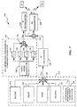
- FIG. 7 shows a block diagram of an exemplary cell-site base station transmitter 100 modified to include a preferred embodiment of the interference simulation apparatus of the present invention.
- Transmitter 100 includes a cell-to-subscriber link waveform generation network 110 for producing paging, pilot, sync, actual traffic channels and a baseband interference signal I CB .
- the I CB signal is used in synthesizing the orthogonal component of the signal energy, I O,B, transmitted over the interference simulation channel.
- the waveform generation network 110 includes paging, pilot, sync, forward traffic (i.e., data), and interference orthogonal component generators 124, 128, 132, 136 and 140, respectively, the outputs of which are combined within a digital summation element or adder 142.
- a manually adjustable attenuator may optionally be interposed between digital adder 142 and a first IF upconverter 120.
- first IF upconverter 120 provides an output signal at 70 MHz in response to the supplied baseband signal I O,B .
- cell-site transmitter 100 further includes a non-orthogonal signal interference generator 150.
- Attenuators 160, 170, 180, and 190 are each supplied with a an output from a digital noise process from a white noise generator 200, and are adjusted in response to digital control signals provided by a controller (not shown).
- the resulting interference components created by attenuators 160, 170, 180, 190 (L ai ) are then combined within a digital summation element or adder 210.
- the output of digital adder 210 is translated in frequency to 70 MHz by a second IF upconverter 220 prior to being provided to an input port of a digital adder 230.
- the signals representative of orthogonal and non-orthogonal component interference are combined within digital adder 230 to form a composite interference signal S c .
- the composite interference signal S c is then radiated by an RF transmitter 260 to one or more subscriber units (SU) within the simulated cell.
- SU subscriber units
- a single interference channel component generator 140 is shown, which is designed to generate an interference signal representative of up to twelve orthogonal traffic channels.
- a first set of six traffic channels may be simulated over a first interference channel covered by a first Walsh code W 1
- a second set of six traffic channels may be simulated over a second interference channel covered by a second Walsh code W 2 .
- a limiting factor in the number of simulated channels per interface is the gain settings. A large gain setting can cause saturation which would not accurately represent the output power from a corresponding number of users.
- additional simulated channels may be developed by using additional traffic channel resources such that for each Walsh code as additional six simulated traffic channels are provided.
- interference generator 140 includes a convolutional encoder 300 for receiving a repetitive sequence of identical non-zero data frames (D) at a predetermined rate (e.g., 9.6 kbps).
- the input data is convolutional encoded with code symbol repetition in accordance with the input data rate and sequence length of Walsh codes W 1 and W 2 .
- each symbol is rate 1/2 convolutionally encoded so as to create a coded symbol stream at 19.2 ksps.
- an input stage of interference component generator 140 further includes an interleaver 310, a modulo-2 adder or exclusive-OR gate 315, as well as a long code PN generator 317 and a decimator 319 for generating PN scrambling code PNs.
- the encoded data from encoder 300 is provided to interleaver 310 where, in the exemplary embodiment, it is convolutional interleaved.
- the interleaved symbol data is then output from interleaver 310 at the exemplary rate of 19.2 ksps to an input of exclusive-OR gate 315, and is scrambled by a PN scrambling code PN sequence provided to another input of exclusive-OR gate 315, from decimator 319.
- PN generator 317 operates to provide, in accordance with the supplied PN mask, a long PN code at a fixed chip rate of 1.228 Mchp/s to decimator 319.
- the use of the PN mask provides a shift in the PN code which provides uniqueness for the user.
- Decimator 319 produces a scrambling PN code of an exemplary rate of 19.2 ksps from the long PN code by using one of every 64 chips produced by PN generator 317.
- exclusive-OR gate 315 The output of exclusive-OR gate 315 is provided to an input of each of two modulo-2 adders or exclusive-OR gates 321 and 323.
- the Walsh code sequence W 1 is provided as a second input to exclusive-OR gate 321, while the Walsh sequence W 2 is supplied as a second input to exclusive-OR gate 323.
- the scrambled symbol data and Walsh sequence W 1 are modulo-2 added (exclusive-OR'ed) by exclusive-OR gate 321, with the result provided as an input to each of two modulo-2 adders or exclusive-OR gates 327 and 329.
- Pseudorandom noise PN I and PN Q sequences corresponding to a particular cell sector or address are provided as second inputs to exclusive-OR gates 327 and 329, respectively.
- the PN I and PN Q signals are exclusive-OR'ed with the output of exclusive-OR gate 321 providing results which are in turn provided as inputs to Finite Impulse Response (FIR) filters 333 and 335, respectively.
- FIR Finite Impulse Response
- the input symbols are filtered according to an input data rate label from interleaver 310.
- the filtered signals output from FIR filters 333 and 335 are provided to a portion of transmit power control circuitry comprising two gain control elements 337 and 339.
- a 7-bit gain control word G 1 derived as described above in reference to the ORTHOGONAL INTERFERENCE SIMULATION procedure, is provided to each of the two gain control elements 337 and 339.
- gain control word G 1 is selected to be such that the orthogonal component of power S radiated over the interference simulation channel covered by Walsh symbol W 1 corresponds to transmission of N s simulated traffic channels at an equivalent rate r eq , where N s ⁇ ⁇ 0,1,2,3 ⁇ .
- gain control word G 1 is preferably updated at 20 millisecond intervals to adequately simulate fluctuations in voice activity.
- the signals output from gain control elements 337 and 339 are combined within a data combiner 343 which operates to produce a first baseband interference signal I O,B1 .
- the scrambled symbol data is also exclusive-OR'ed with Walsh sequence W 2 using exclusive-OR gate 323, with the result provided as an input to each of two modulo-2 adders or exclusive-OR gates 349 and 351.
- the pseudorandom noise PN I and PN Q sequences are also provided as second inputs to exclusive-OR gates 349 and 351, respectively, in order to allow modulo-2 adding (exclusive-OR'ing) with the output of exclusive-OR gate 321.
- the symbol stream produced by exclusive-OR gate 321 is filtered by Finite Impulse Response (FIR) filters 353 and 355, with the resulting filtered signals being provided to a portion of transmit power control circuitry comprising two gain control elements 357 and 359.
- FIR Finite Impulse Response
- a 7-bit gain control word G 2 is selected to be such that the orthogonal interference component covered by Walsh symbol W 2 corresponds to a desired number of simulated traffic channels (i.e., 0,1, 2 or 3) is provided to gain control elements 357 and 359.
- the signals output from gain control elements 357 and 359 are combined within a data combiner 343 to produce a second baseband interference signal I O,B2 .
- the two I O,B1 and I O,B2 signals are further combined by superposition of the two signals by data combiner 343 to generate a composite baseband interference signal I CB .
- the I CB signal is output by data combiner 343 and provided as an input to digital adder 142 ( Figure 7).
Landscapes
- Engineering & Computer Science (AREA)
- Computer Networks & Wireless Communication (AREA)
- Signal Processing (AREA)
- Physics & Mathematics (AREA)
- Electromagnetism (AREA)
- Spectroscopy & Molecular Physics (AREA)
- Quality & Reliability (AREA)
- Mobile Radio Communication Systems (AREA)
- Radio Relay Systems (AREA)
- Noise Elimination (AREA)
- Monitoring And Testing Of Transmission In General (AREA)
- Radar Systems Or Details Thereof (AREA)
Applications Claiming Priority (3)
| Application Number | Priority Date | Filing Date | Title |
|---|---|---|---|
| US27460994A | 1994-07-13 | 1994-07-13 | |
| US274609 | 1994-07-13 | ||
| PCT/US1995/008890 WO1996002987A1 (en) | 1994-07-13 | 1995-07-13 | Method and apparatus for simulating interference received by subscribers in a spread spectrum communications system |
Publications (2)
| Publication Number | Publication Date |
|---|---|
| EP0719480A1 EP0719480A1 (en) | 1996-07-03 |
| EP0719480B1 true EP0719480B1 (en) | 2001-09-26 |
Family
ID=23048919
Family Applications (1)
| Application Number | Title | Priority Date | Filing Date |
|---|---|---|---|
| EP95926700A Expired - Lifetime EP0719480B1 (en) | 1994-07-13 | 1995-07-13 | Method and apparatus for simulating interference received by subscribers in a spread spectrum communications system |
Country Status (20)
| Country | Link |
|---|---|
| US (1) | US5596570A (enExample) |
| EP (1) | EP0719480B1 (enExample) |
| JP (1) | JP3078329B2 (enExample) |
| KR (1) | KR100341959B1 (enExample) |
| CN (1) | CN1130046C (enExample) |
| AT (1) | ATE206257T1 (enExample) |
| AU (1) | AU700994B2 (enExample) |
| BR (1) | BR9506049A (enExample) |
| CA (1) | CA2170517A1 (enExample) |
| DE (1) | DE69522918T2 (enExample) |
| DK (1) | DK0719480T3 (enExample) |
| ES (1) | ES2164161T3 (enExample) |
| FI (1) | FI961149A7 (enExample) |
| IL (1) | IL114559A0 (enExample) |
| MX (1) | MX9600953A (enExample) |
| PT (1) | PT719480E (enExample) |
| RU (1) | RU2189114C2 (enExample) |
| TW (1) | TW275731B (enExample) |
| WO (1) | WO1996002987A1 (enExample) |
| ZA (1) | ZA955600B (enExample) |
Families Citing this family (106)
| Publication number | Priority date | Publication date | Assignee | Title |
|---|---|---|---|---|
| US5103459B1 (en) * | 1990-06-25 | 1999-07-06 | Qualcomm Inc | System and method for generating signal waveforms in a cdma cellular telephone system |
| US6693951B1 (en) * | 1990-06-25 | 2004-02-17 | Qualcomm Incorporated | System and method for generating signal waveforms in a CDMA cellular telephone system |
| US5754961A (en) | 1994-06-20 | 1998-05-19 | Kabushiki Kaisha Toshiba | Radio communication system including SDL having transmission rate of relatively high speed |
| ZA955605B (en) * | 1994-07-13 | 1996-04-10 | Qualcomm Inc | System and method for simulating user interference received by subscriber units in a spread spectrum communication network |
| GB2296625B (en) * | 1994-12-23 | 1999-04-14 | Nokia Mobile Phones Ltd | Apparatus and method for data transmission |
| US5696789A (en) * | 1995-03-06 | 1997-12-09 | Unisys Corporation | Apparatus and method for signal identification |
| US5812522A (en) * | 1995-03-31 | 1998-09-22 | Airtouch Communications, Inc. | Location-ruled radio-integrated network |
| US6697350B2 (en) | 1995-06-30 | 2004-02-24 | Interdigital Technology Corporation | Adaptive vector correlator for spread-spectrum communications |
| US6940840B2 (en) | 1995-06-30 | 2005-09-06 | Interdigital Technology Corporation | Apparatus for adaptive reverse power control for spread-spectrum communications |
| ZA965340B (en) | 1995-06-30 | 1997-01-27 | Interdigital Tech Corp | Code division multiple access (cdma) communication system |
| US7020111B2 (en) * | 1996-06-27 | 2006-03-28 | Interdigital Technology Corporation | System for using rapid acquisition spreading codes for spread-spectrum communications |
| US7123600B2 (en) * | 1995-06-30 | 2006-10-17 | Interdigital Technology Corporation | Initial power control for spread-spectrum communications |
| US6816473B2 (en) | 1995-06-30 | 2004-11-09 | Interdigital Technology Corporation | Method for adaptive forward power control for spread-spectrum communications |
| US6788662B2 (en) | 1995-06-30 | 2004-09-07 | Interdigital Technology Corporation | Method for adaptive reverse power control for spread-spectrum communications |
| US7072380B2 (en) * | 1995-06-30 | 2006-07-04 | Interdigital Technology Corporation | Apparatus for initial power control for spread-spectrum communications |
| US6487190B1 (en) | 1996-06-27 | 2002-11-26 | Interdigital Technology Corporation | Efficient multichannel filtering for CDMA modems |
| US6049535A (en) * | 1996-06-27 | 2000-04-11 | Interdigital Technology Corporation | Code division multiple access (CDMA) communication system |
| US7929498B2 (en) * | 1995-06-30 | 2011-04-19 | Interdigital Technology Corporation | Adaptive forward power control and adaptive reverse power control for spread-spectrum communications |
| US6885652B1 (en) * | 1995-06-30 | 2005-04-26 | Interdigital Technology Corporation | Code division multiple access (CDMA) communication system |
| US5794128A (en) * | 1995-09-20 | 1998-08-11 | The United States Of America As Represented By The Secretary Of The Army | Apparatus and processes for realistic simulation of wireless information transport systems |
| FR2739512B1 (fr) * | 1995-10-03 | 1997-10-31 | France Telecom | Modelisation des interferences dans un reseau radiotelephonique cellulaire |
| US5848160A (en) * | 1996-02-20 | 1998-12-08 | Raytheon Company | Digital synthesized wideband noise-like waveform |
| US6308072B1 (en) * | 1996-04-26 | 2001-10-23 | Motorola, Inc. | Method and apparatus for controlling a wireless communication system |
| US6678311B2 (en) | 1996-05-28 | 2004-01-13 | Qualcomm Incorporated | High data CDMA wireless communication system using variable sized channel codes |
| US5724363A (en) * | 1996-06-21 | 1998-03-03 | Breya; Edward F. | Optical analog signal transmission system |
| US6067446A (en) * | 1996-07-11 | 2000-05-23 | Telefonaktiebolaget Lm Ericsson | Power presetting in a radio communication system |
| IL119694A0 (en) | 1996-11-26 | 1997-06-10 | Point Ltd V | A method and device to disable cellular communication |
| GB2320648A (en) * | 1996-12-20 | 1998-06-24 | Dsc Telecom Lp | Controlling interference in a cell of a wireless telecommunications system |
| JP3585333B2 (ja) * | 1996-12-26 | 2004-11-04 | 松下電器産業株式会社 | Cdma基地局装置 |
| US5978650A (en) * | 1997-01-21 | 1999-11-02 | Adc Telecommunications, Inc. | System and method for transmitting data |
| US6122266A (en) * | 1997-02-19 | 2000-09-19 | Lucent Technologies Inc. | Multi-level sectorized CDMA communications |
| US6009129A (en) * | 1997-02-28 | 1999-12-28 | Nokia Mobile Phones | Device and method for detection and reduction of intermodulation distortion |
| ES2292202T3 (es) * | 1997-06-02 | 2008-03-01 | Netline Communications Technologies (Nct) Ltd. | Cortafuegos para comunicaciones celulares. |
| US5983080A (en) * | 1997-06-03 | 1999-11-09 | At & T Corp | Apparatus and method for generating voice signals at a wireless communications station |
| US6075792A (en) * | 1997-06-16 | 2000-06-13 | Interdigital Technology Corporation | CDMA communication system which selectively allocates bandwidth upon demand |
| US6405043B1 (en) * | 1997-07-02 | 2002-06-11 | Scoreboard, Inc. | Method to characterize the prospective or actual level of interference at a point, in a sector, and throughout a cellular system |
| US6052584A (en) * | 1997-07-24 | 2000-04-18 | Bell Atlantic Nynex Mobile | CDMA cellular system testing, analysis and optimization |
| US20020051434A1 (en) * | 1997-10-23 | 2002-05-02 | Ozluturk Fatih M. | Method for using rapid acquisition spreading codes for spread-spectrum communications |
| US5973638A (en) * | 1998-01-30 | 1999-10-26 | Micronetics Wireless, Inc. | Smart antenna channel simulator and test system |
| US6236363B1 (en) | 1998-01-30 | 2001-05-22 | Micronetics Wireless | Smart antenna channel simulator and test system |
| US6188892B1 (en) * | 1998-02-13 | 2001-02-13 | Qualcomm Inc. | System and method for base station initiated call setup |
| SE513988C2 (sv) * | 1998-03-30 | 2000-12-04 | Ericsson Telefon Ab L M | Förfarande och anordning för alstring av interferens över luftgränssnittet i ett cellulärt nät |
| DE69934864T2 (de) * | 1998-05-20 | 2007-10-18 | Ntt Docomo Inc. | Interferenzloses radiokommunikationssystem |
| KR20000014423A (ko) | 1998-08-17 | 2000-03-15 | 윤종용 | 부호분할다중접속 통신시스템의 통신제어장치 및 방법 |
| KR100270376B1 (ko) | 1998-08-19 | 2000-11-01 | 윤종용 | 무선데이터 서비스장치의 기능시험을 위한 회선 호 발생기 및기능시험 방법 |
| US7190688B1 (en) * | 1998-09-21 | 2007-03-13 | Lucent Technologies Inc. | Method and apparatus for adaptive setting of initial traffic power |
| DE69937061T2 (de) * | 1998-09-21 | 2008-05-29 | Nokia Corp. | Gerät und verfahren zur leistungsregelung eines kommunikationsgerätes |
| US6377555B1 (en) * | 1998-09-22 | 2002-04-23 | Jhong Sam Lee | Method for determining forward link channel powers for a CDMA cellular or PCS system |
| US6690652B1 (en) * | 1998-10-26 | 2004-02-10 | International Business Machines Corporation | Adaptive power control in wideband CDMA cellular systems (WCDMA) and methods of operation |
| GB9828209D0 (en) * | 1998-12-21 | 1999-02-17 | Northern Telecom Ltd | A cellular communications system |
| US6360094B1 (en) * | 1998-12-21 | 2002-03-19 | Nortel Networks Limited | Method for locating antenna problems in a cellular communications network |
| US6766164B1 (en) * | 1999-01-19 | 2004-07-20 | Lucent Technologies Inc. | System and method for providing radio frequency conditions for testing wireless communications equipment |
| US6498934B1 (en) | 1999-03-24 | 2002-12-24 | Telefonaktiebologet Lm Ericsson (Publ) | Channel allocation using enhanced pathloss estimates |
| KR100305764B1 (ko) * | 1999-06-21 | 2001-11-01 | 서평원 | 무선가입자망 시스템 순방향 전력비 제어장치 및 방법 |
| US6332076B1 (en) * | 1999-06-28 | 2001-12-18 | Ericsson Inc. | Method and system for identifying and analyzing downlink interference sources in a telecommunications network |
| US6298242B1 (en) * | 1999-07-22 | 2001-10-02 | Qualcomm Inc. | Method and apparatus for reducing frame error rate through signal power adjustment |
| US6442384B1 (en) * | 1999-10-22 | 2002-08-27 | Ericsson Inc. | System and method for identification of uplink/downlink interference sources |
| JP3688166B2 (ja) | 1999-11-26 | 2005-08-24 | シャープ株式会社 | Cdma変調方法及びその装置 |
| US6542538B2 (en) | 2000-01-10 | 2003-04-01 | Qualcomm Incorporated | Method and apparatus for testing wireless communication channels |
| US6885694B1 (en) | 2000-02-29 | 2005-04-26 | Telefonaktiebolaget Lm Ericsson (Publ) | Correction of received signal and interference estimates |
| US6668333B1 (en) * | 2000-02-29 | 2003-12-23 | Agere Systems Inc. | Method and apparatus for evaluating effects of switching noise in digital and analog circuitry |
| US6456851B1 (en) * | 2000-03-06 | 2002-09-24 | Aurora Networks, Inc. | Wireless communications architecture |
| KR100854201B1 (ko) * | 2000-05-12 | 2008-08-26 | 콸콤 인코포레이티드 | Cdma 중간 데이터율 시스템의 안정성 및 용량을 개선하기 위한 방법 및 장치 |
| US6816709B2 (en) | 2000-08-19 | 2004-11-09 | Pctel Maryland, Inc. | Method and apparatus for testing CDMA signal propagation and coverage |
| US20050198688A1 (en) * | 2000-09-19 | 2005-09-08 | Fong Thomas K.T. | System and method for digitally monitoring a cable plant |
| US6560440B1 (en) | 2000-10-10 | 2003-05-06 | General Dynamics Decision Systems, Inc. | Method for precompensating frequency data for use in high-velocity satellite communication systems |
| US6999500B2 (en) * | 2000-11-03 | 2006-02-14 | Qualcomm Inc. | System for direct sequence spreading |
| US6961431B2 (en) * | 2001-02-28 | 2005-11-01 | Lockheed Martin Corp. | Analog privacy scrambler and scrambling method |
| US20020183053A1 (en) * | 2001-05-29 | 2002-12-05 | Muralimohan Gopalakrishna | Methods and systems for testing macrodiversity and handover functionality of a radio network controller |
| US7024161B1 (en) | 2001-08-08 | 2006-04-04 | Cellco Partnership | Modular wireless device test set |
| US7603081B2 (en) * | 2001-09-14 | 2009-10-13 | Atc Technologies, Llc | Radiotelephones and operating methods that use a single radio frequency chain and a single baseband processor for space-based and terrestrial communications |
| EP1298949B1 (en) * | 2001-09-28 | 2005-03-02 | Motorola, Inc. | Communication system with detection of extra-system interference |
| FI113313B (fi) * | 2001-11-27 | 2004-03-31 | Elektrobit Oy | Menetelmä ja laitteisto radiokanavan simuloimiseksi |
| RU2216792C2 (ru) * | 2001-11-28 | 2003-11-20 | Самсунг Электроникс Ко., Лтд. | Способ моделирования сигнала, считываемого с оптического диска |
| RU2216053C2 (ru) * | 2001-11-28 | 2003-11-10 | Самсунг Электроникс Ко., Лтд. | Способ определения оптимальных параметров оптического диска |
| US7286802B2 (en) | 2002-02-15 | 2007-10-23 | Dyaptive Systems Incorporated | Wireless simulator |
| US6973188B1 (en) * | 2002-02-25 | 2005-12-06 | Lockheed Martin Corporation | Analog scrambler |
| US6876868B2 (en) * | 2002-04-08 | 2005-04-05 | Motorola, Inc. | System and method for predictive transmit power control for mobile stations in a multiple access wireless communication system |
| US7184713B2 (en) * | 2002-06-20 | 2007-02-27 | Qualcomm, Incorporated | Rate control for multi-channel communication systems |
| DE10229860A1 (de) * | 2002-07-03 | 2004-01-29 | Infineon Technologies Ag | Verfahren und Sendevorrichtung zum Übertragen eines zweiwertigen Signals |
| US7411974B2 (en) * | 2002-11-14 | 2008-08-12 | Qualcomm Incorporated | Wireless communication rate shaping |
| US7411923B2 (en) * | 2002-11-14 | 2008-08-12 | Qualcomm Incorporated | Wireless communication rate shaping |
| DE102004008444A1 (de) * | 2004-02-19 | 2005-09-08 | Global Scaling Technologies Ag | Verfahren und Einrichtung zur drahtlosen Datenübertragung |
| IL161419A (en) | 2004-04-15 | 2010-02-17 | Alvarion Ltd | Handling communication interferences in wireless systems |
| US7054781B2 (en) * | 2004-05-25 | 2006-05-30 | Elektrobit Oy | Radio channel simulation |
| US7129753B2 (en) * | 2004-05-26 | 2006-10-31 | Infineon Technologies Ag | Chip to chip interface |
| US7551582B2 (en) * | 2004-10-12 | 2009-06-23 | Nextel Communications Inc. | System and method for optimizing walsh code assignments |
| US7400887B2 (en) * | 2005-03-17 | 2008-07-15 | Lucent Technologies Inc. | Method for estimating the downlink capacity in a spread spectrum wireless communications system |
| US8920343B2 (en) | 2006-03-23 | 2014-12-30 | Michael Edward Sabatino | Apparatus for acquiring and processing of physiological auditory signals |
| US20070230356A1 (en) * | 2006-04-04 | 2007-10-04 | Kalantri Sacchindrakumar G | Method and apparatus for enabling FLO device certification |
| US8244292B2 (en) * | 2007-02-23 | 2012-08-14 | Samsung Electronics Co., Ltd | Apparatus and method for power distribution by frequency allocation in multi-frequency allocation broadband wireless communication system |
| DE102007010868A1 (de) * | 2007-03-06 | 2008-09-11 | Rohde & Schwarz Gmbh & Co. Kg | Vorrichtung und Verfahren zur Ermittlung eines Übertragungsverhaltens von Unterkanälen |
| CN101335962B (zh) * | 2007-06-25 | 2012-07-25 | 电信科学技术研究院 | 一种模拟蜂窝网络环境下的信号发生方法及装置 |
| DE102008018385A1 (de) * | 2008-04-11 | 2009-10-15 | Rohde & Schwarz Gmbh & Co. Kg | Testgerät zum Testen der Übertragungsqualität eines Funkgeräts |
| US8868452B2 (en) * | 2008-05-01 | 2014-10-21 | Accenture Global Services Limited | Smart grid deployment simulator |
| US8014436B2 (en) * | 2008-07-02 | 2011-09-06 | Telefonaktiebolaget L M Ericsson (Publ) | Multi-dimensional signal of reduced peak-to-RMS ratio |
| US8711760B2 (en) * | 2010-03-26 | 2014-04-29 | Intel Corporation | Method and apparatus to adjust received signal |
| US9125068B2 (en) | 2010-06-04 | 2015-09-01 | Ixia | Methods, systems, and computer readable media for simulating realistic movement of user equipment in a long term evolution (LTE) network |
| US9596166B2 (en) | 2013-04-26 | 2017-03-14 | Ixia | Methods, systems, and computer readable media for testing inter-cell interference coordination capabilities of wireless access access nodes |
| WO2014186747A1 (en) | 2013-05-16 | 2014-11-20 | Ixia | Methods, systems, and computer readable media for frequency selective channel modeling |
| US10542443B2 (en) | 2017-10-27 | 2020-01-21 | Keysight Technologies, Inc. | Methods, systems, and computer readable media for testing long term evolution (LTE) air interface device using emulated noise in unassigned resource blocks (RBs) |
| RU191159U1 (ru) * | 2019-05-06 | 2019-07-25 | ФЕДЕРАЛЬНОЕ ГОСУДАРСТВЕННОЕ КАЗЕННОЕ ВОЕННОЕ ОБРАЗОВАТЕЛЬНОЕ УЧРЕЖДЕНИЕ ВЫСШЕГО ОБРАЗОВАНИЯ Военная академия Ракетных войск стратегического назначения имени Петра Великого МИНИСТЕРСТВА ОБОРОНЫ РОССИЙСКОЙ ФЕДЕРАЦИИ | Устройство для моделирования системы связи |
| US11089495B2 (en) | 2019-07-11 | 2021-08-10 | Keysight Technologies, Inc. | Methods, systems, and computer readable media for testing radio access network nodes by emulating band-limited radio frequency (RF) and numerology-capable UEs in a wideband 5G network |
| CN111399804B (zh) * | 2020-03-04 | 2023-07-25 | 成都卫士通信息产业股份有限公司 | 一种随机数生成方法、装置、智能移动终端及存储介质 |
| EP4384919B1 (en) * | 2022-08-01 | 2025-12-03 | Qualcomm Incorporated | Using retired pages history for instruction translation lookaside buffer (tlb) prefetching in processor-based devices |
| US20240037042A1 (en) * | 2022-08-01 | 2024-02-01 | Qualcomm Incorporated | Using retired pages history for instruction translation lookaside buffer (tlb) prefetching in processor-based devices |
Family Cites Families (16)
| Publication number | Priority date | Publication date | Assignee | Title |
|---|---|---|---|---|
| US4317214A (en) * | 1980-07-14 | 1982-02-23 | Attinello John S | Apparatus for simulating interference transmissions |
| US4470138A (en) * | 1982-11-04 | 1984-09-04 | The United States Of America As Represented By The Secretary Of The Army | Non-orthogonal mobile subscriber multiple access system |
| US4901307A (en) | 1986-10-17 | 1990-02-13 | Qualcomm, Inc. | Spread spectrum multiple access communication system using satellite or terrestrial repeaters |
| US5056109A (en) * | 1989-11-07 | 1991-10-08 | Qualcomm, Inc. | Method and apparatus for controlling transmission power in a cdma cellular mobile telephone system |
| US5148548A (en) * | 1989-12-19 | 1992-09-15 | Northern Telecom Limited | Method of monitoring cellular radio channels to avoid adjacent and co-channel interference |
| US5103459B1 (en) | 1990-06-25 | 1999-07-06 | Qualcomm Inc | System and method for generating signal waveforms in a cdma cellular telephone system |
| US5136612A (en) * | 1990-12-31 | 1992-08-04 | At&T Bell Laboratories | Method and apparatus for reducing effects of multiple access interference in a radio receiver in a code division multiple access communication system |
| RU2013866C1 (ru) * | 1991-01-22 | 1994-05-30 | Военная академия связи | Радиолиния дистанционного управления |
| RU2002372C1 (ru) * | 1991-05-05 | 1993-10-30 | Воронежский научно-исследовательский институт св зи | Устройство дл измерени относительных уровней побочных колебаний радиопередатчиков |
| RU2007878C1 (ru) * | 1991-05-05 | 1994-02-15 | Пензенский научно-исследовательский электротехнический институт | Устройство для оценки состояния и управления каналами и техническими средствами в симплексных системах связи |
| RU2002373C1 (ru) * | 1991-06-17 | 1993-10-30 | Воронежский научно-исследовательский институт св зи | Устройство дл контрол чувствительности побочных каналов в радиоприемниках |
| JP2674404B2 (ja) * | 1991-12-13 | 1997-11-12 | 日本電気株式会社 | 基地局カバレッジエリア制御方式 |
| WO1993015569A1 (en) * | 1992-01-28 | 1993-08-05 | Comarco, Incorporated | Automatic cellular telephone control system |
| FI94809C (fi) * | 1992-04-01 | 1995-10-25 | Ne Products Oy | Radiokanavan häipymissimulaattori ja menetelmä häipymisen simuloimiseksi |
| US5410737A (en) * | 1992-04-27 | 1995-04-25 | American Pcs L.P. | Frequency agile sharing technology (FAST) for a personal communications service system |
| US5224122A (en) * | 1992-06-29 | 1993-06-29 | Motorola, Inc. | Method and apparatus for canceling spread-spectrum noise |
-
1995
- 1995-07-05 ZA ZA955600A patent/ZA955600B/xx unknown
- 1995-07-08 TW TW084107076A patent/TW275731B/zh active
- 1995-07-12 IL IL11455995A patent/IL114559A0/xx active IP Right Grant
- 1995-07-13 RU RU96107777/09A patent/RU2189114C2/ru not_active IP Right Cessation
- 1995-07-13 ES ES95926700T patent/ES2164161T3/es not_active Expired - Lifetime
- 1995-07-13 BR BR9506049A patent/BR9506049A/pt not_active IP Right Cessation
- 1995-07-13 CA CA002170517A patent/CA2170517A1/en not_active Abandoned
- 1995-07-13 DK DK95926700T patent/DK0719480T3/da active
- 1995-07-13 AT AT95926700T patent/ATE206257T1/de not_active IP Right Cessation
- 1995-07-13 MX MX9600953A patent/MX9600953A/es unknown
- 1995-07-13 AU AU30990/95A patent/AU700994B2/en not_active Ceased
- 1995-07-13 EP EP95926700A patent/EP0719480B1/en not_active Expired - Lifetime
- 1995-07-13 KR KR1019960701260A patent/KR100341959B1/ko not_active Expired - Fee Related
- 1995-07-13 JP JP08505187A patent/JP3078329B2/ja not_active Expired - Fee Related
- 1995-07-13 WO PCT/US1995/008890 patent/WO1996002987A1/en not_active Ceased
- 1995-07-13 CN CN95190630A patent/CN1130046C/zh not_active Expired - Fee Related
- 1995-07-13 PT PT95926700T patent/PT719480E/pt unknown
- 1995-07-13 DE DE69522918T patent/DE69522918T2/de not_active Expired - Lifetime
-
1996
- 1996-03-12 FI FI961149A patent/FI961149A7/fi unknown
- 1996-05-22 US US08/651,310 patent/US5596570A/en not_active Expired - Lifetime
Also Published As
| Publication number | Publication date |
|---|---|
| BR9506049A (pt) | 1997-08-05 |
| HK1015194A1 (en) | 1999-10-08 |
| RU2189114C2 (ru) | 2002-09-10 |
| EP0719480A1 (en) | 1996-07-03 |
| CA2170517A1 (en) | 1996-02-01 |
| TW275731B (enExample) | 1996-05-11 |
| AU3099095A (en) | 1996-02-16 |
| KR100341959B1 (ko) | 2002-11-22 |
| FI961149A7 (fi) | 1996-05-10 |
| ES2164161T3 (es) | 2002-02-16 |
| IL114559A0 (en) | 1995-11-27 |
| JPH09503119A (ja) | 1997-03-25 |
| PT719480E (pt) | 2002-03-28 |
| ZA955600B (en) | 1996-04-02 |
| WO1996002987A1 (en) | 1996-02-01 |
| DK0719480T3 (da) | 2002-01-21 |
| MX9600953A (es) | 1997-06-28 |
| US5596570A (en) | 1997-01-21 |
| JP3078329B2 (ja) | 2000-08-21 |
| CN1130451A (zh) | 1996-09-04 |
| AU700994B2 (en) | 1999-01-14 |
| KR960705419A (ko) | 1996-10-09 |
| FI961149A0 (fi) | 1996-03-12 |
| ATE206257T1 (de) | 2001-10-15 |
| DE69522918D1 (de) | 2001-10-31 |
| CN1130046C (zh) | 2003-12-03 |
| DE69522918T2 (de) | 2002-07-04 |
Similar Documents
| Publication | Publication Date | Title |
|---|---|---|
| EP0719480B1 (en) | Method and apparatus for simulating interference received by subscribers in a spread spectrum communications system | |
| AU688090B2 (en) | Method and apparatus for simulating user interference in a spread spectrum communications system | |
| Lee | Overview of cellular CDMA | |
| JP3325890B2 (ja) | Cdmaマイクロセルラテレフォンシステム及び分配アンテナシステム | |
| US5751761A (en) | System and method for orthogonal spread spectrum sequence generation in variable data rate systems | |
| US6473447B1 (en) | Dynamic sectorization in a spread spectrum communication system | |
| US6185246B1 (en) | System and method for orthogonal spread spectrum sequence generation in variable data rate systems | |
| US5497395A (en) | Method and apparatus for modulating signal waveforms in a CDMA communication system | |
| KR0134390B1 (ko) | 코드분할 다중접속(cdma) 셀룰라 전화 시스템에서 신호파형을 발생하기 위한 장치 및 방법 | |
| MXPA96000954A (es) | Sistema y metodo para simular interferencia delusuario en una red de comunicaciones de espectrodifundido | |
| Bi et al. | The performance of DS-CDMA for wireless local loop | |
| HK1015194B (en) | Method and apparatus for simulating interference received by subscribers in a spread spectrum communications system | |
| EP1266460B1 (en) | Methods, systems and apparatus for precompensating for interference among transmitted coded cdma signals | |
| Mohr et al. | Downlink performance of IS-95 DS-CDMA under multipath propagation conditions | |
| Karmaker | Planning and design of CDMA based cellular network for dhaka city | |
| Grujev et al. | Hybrid DS/SFH CDMA system with near-far effect and imperfect power control | |
| HK1015195B (en) | Method and apparatus for simulating user interference in a spread spectrum communications system | |
| MXPA00003577A (en) | Methods and apparatus for measuring nonlinear effects in a communication system and for selecting channels on the basis of the results |
Legal Events
| Date | Code | Title | Description |
|---|---|---|---|
| PUAI | Public reference made under article 153(3) epc to a published international application that has entered the european phase |
Free format text: ORIGINAL CODE: 0009012 |
|
| AK | Designated contracting states |
Kind code of ref document: A1 Designated state(s): AT BE CH DE DK ES FR GB GR IE IT LI LU MC NL PT SE |
|
| AX | Request for extension of the european patent |
Free format text: LT PAYMENT 960412;LV PAYMENT 960412;SI PAYMENT 960412 |
|
| RAX | Requested extension states of the european patent have changed |
Free format text: LT PAYMENT 960412;LV PAYMENT 960412;SI PAYMENT 960412 |
|
| 17P | Request for examination filed |
Effective date: 19960731 |
|
| 17Q | First examination report despatched |
Effective date: 19981102 |
|
| GRAG | Despatch of communication of intention to grant |
Free format text: ORIGINAL CODE: EPIDOS AGRA |
|
| GRAG | Despatch of communication of intention to grant |
Free format text: ORIGINAL CODE: EPIDOS AGRA |
|
| GRAG | Despatch of communication of intention to grant |
Free format text: ORIGINAL CODE: EPIDOS AGRA |
|
| GRAH | Despatch of communication of intention to grant a patent |
Free format text: ORIGINAL CODE: EPIDOS IGRA |
|
| RAP1 | Party data changed (applicant data changed or rights of an application transferred) |
Owner name: QUALCOMM INCORPORATED |
|
| GRAH | Despatch of communication of intention to grant a patent |
Free format text: ORIGINAL CODE: EPIDOS IGRA |
|
| GRAH | Despatch of communication of intention to grant a patent |
Free format text: ORIGINAL CODE: EPIDOS IGRA |
|
| GRAA | (expected) grant |
Free format text: ORIGINAL CODE: 0009210 |
|
| AK | Designated contracting states |
Kind code of ref document: B1 Designated state(s): AT BE CH DE DK ES FR GB GR IE IT LI LU MC NL PT SE |
|
| AX | Request for extension of the european patent |
Free format text: LT PAYMENT 19960412;LV PAYMENT 19960412;SI PAYMENT 19960412 |
|
| LTIE | Lt: invalidation of european patent or patent extension | ||
| REF | Corresponds to: |
Ref document number: 206257 Country of ref document: AT Date of ref document: 20011015 Kind code of ref document: T |
|
| REG | Reference to a national code |
Ref country code: CH Ref legal event code: EP |
|
| REF | Corresponds to: |
Ref document number: 69522918 Country of ref document: DE Date of ref document: 20011031 |
|
| REG | Reference to a national code |
Ref country code: IE Ref legal event code: FG4D |
|
| REG | Reference to a national code |
Ref country code: GB Ref legal event code: IF02 |
|
| REG | Reference to a national code |
Ref country code: CH Ref legal event code: NV Representative=s name: R. A. EGLI & CO. PATENTANWAELTE |
|
| REG | Reference to a national code |
Ref country code: DK Ref legal event code: T3 |
|
| REG | Reference to a national code |
Ref country code: ES Ref legal event code: FG2A Ref document number: 2164161 Country of ref document: ES Kind code of ref document: T3 |
|
| ET | Fr: translation filed | ||
| REG | Reference to a national code |
Ref country code: PT Ref legal event code: SC4A Free format text: AVAILABILITY OF NATIONAL TRANSLATION Effective date: 20011219 |
|
| REG | Reference to a national code |
Ref country code: GR Ref legal event code: EP Ref document number: 20010402522 Country of ref document: GR |
|
| PLBE | No opposition filed within time limit |
Free format text: ORIGINAL CODE: 0009261 |
|
| STAA | Information on the status of an ep patent application or granted ep patent |
Free format text: STATUS: NO OPPOSITION FILED WITHIN TIME LIMIT |
|
| 26N | No opposition filed | ||
| PGFP | Annual fee paid to national office [announced via postgrant information from national office to epo] |
Ref country code: MC Payment date: 20030624 Year of fee payment: 9 |
|
| PGFP | Annual fee paid to national office [announced via postgrant information from national office to epo] |
Ref country code: BE Payment date: 20030911 Year of fee payment: 9 |
|
| PG25 | Lapsed in a contracting state [announced via postgrant information from national office to epo] |
Ref country code: MC Free format text: LAPSE BECAUSE OF NON-PAYMENT OF DUE FEES Effective date: 20040731 Ref country code: BE Free format text: LAPSE BECAUSE OF NON-PAYMENT OF DUE FEES Effective date: 20040731 |
|
| BERE | Be: lapsed |
Owner name: *QUALCOMM INC. Effective date: 20040731 |
|
| BERE | Be: lapsed |
Owner name: *QUALCOMM INC. Effective date: 20040731 |
|
| PGFP | Annual fee paid to national office [announced via postgrant information from national office to epo] |
Ref country code: PT Payment date: 20100621 Year of fee payment: 16 Ref country code: IE Payment date: 20100616 Year of fee payment: 16 Ref country code: DK Payment date: 20100615 Year of fee payment: 16 |
|
| PGFP | Annual fee paid to national office [announced via postgrant information from national office to epo] |
Ref country code: NL Payment date: 20100709 Year of fee payment: 16 Ref country code: ES Payment date: 20100701 Year of fee payment: 16 Ref country code: CH Payment date: 20100726 Year of fee payment: 16 |
|
| PGFP | Annual fee paid to national office [announced via postgrant information from national office to epo] |
Ref country code: SE Payment date: 20100708 Year of fee payment: 16 Ref country code: LU Payment date: 20100720 Year of fee payment: 16 Ref country code: IT Payment date: 20100717 Year of fee payment: 16 Ref country code: GB Payment date: 20100616 Year of fee payment: 16 Ref country code: FR Payment date: 20100813 Year of fee payment: 16 Ref country code: DE Payment date: 20100730 Year of fee payment: 16 Ref country code: AT Payment date: 20100616 Year of fee payment: 16 |
|
| PGFP | Annual fee paid to national office [announced via postgrant information from national office to epo] |
Ref country code: GR Payment date: 20100621 Year of fee payment: 16 |
|
| REG | Reference to a national code |
Ref country code: PT Ref legal event code: MM4A Free format text: LAPSE DUE TO NON-PAYMENT OF FEES Effective date: 20120113 |
|
| REG | Reference to a national code |
Ref country code: NL Ref legal event code: V1 Effective date: 20120201 |
|
| REG | Reference to a national code |
Ref country code: CH Ref legal event code: PL |
|
| REG | Reference to a national code |
Ref country code: SE Ref legal event code: EUG |
|
| REG | Reference to a national code |
Ref country code: DK Ref legal event code: EBP |
|
| GBPC | Gb: european patent ceased through non-payment of renewal fee |
Effective date: 20110713 |
|
| REG | Reference to a national code |
Ref country code: GR Ref legal event code: ML Ref document number: 20010402522 Country of ref document: GR Effective date: 20120202 |
|
| REG | Reference to a national code |
Ref country code: AT Ref legal event code: MM01 Ref document number: 206257 Country of ref document: AT Kind code of ref document: T Effective date: 20110713 |
|
| REG | Reference to a national code |
Ref country code: FR Ref legal event code: ST Effective date: 20120330 |
|
| REG | Reference to a national code |
Ref country code: IE Ref legal event code: MM4A |
|
| PG25 | Lapsed in a contracting state [announced via postgrant information from national office to epo] |
Ref country code: LI Free format text: LAPSE BECAUSE OF NON-PAYMENT OF DUE FEES Effective date: 20110731 Ref country code: CH Free format text: LAPSE BECAUSE OF NON-PAYMENT OF DUE FEES Effective date: 20110731 Ref country code: DE Free format text: LAPSE BECAUSE OF NON-PAYMENT OF DUE FEES Effective date: 20120201 Ref country code: FR Free format text: LAPSE BECAUSE OF NON-PAYMENT OF DUE FEES Effective date: 20110801 |
|
| REG | Reference to a national code |
Ref country code: DE Ref legal event code: R119 Ref document number: 69522918 Country of ref document: DE Effective date: 20120201 |
|
| PG25 | Lapsed in a contracting state [announced via postgrant information from national office to epo] |
Ref country code: PT Free format text: LAPSE BECAUSE OF NON-PAYMENT OF DUE FEES Effective date: 20120113 Ref country code: GR Free format text: LAPSE BECAUSE OF NON-PAYMENT OF DUE FEES Effective date: 20120202 Ref country code: NL Free format text: LAPSE BECAUSE OF NON-PAYMENT OF DUE FEES Effective date: 20120201 Ref country code: IT Free format text: LAPSE BECAUSE OF NON-PAYMENT OF DUE FEES Effective date: 20110713 |
|
| PG25 | Lapsed in a contracting state [announced via postgrant information from national office to epo] |
Ref country code: GB Free format text: LAPSE BECAUSE OF NON-PAYMENT OF DUE FEES Effective date: 20110713 |
|
| PG25 | Lapsed in a contracting state [announced via postgrant information from national office to epo] |
Ref country code: IE Free format text: LAPSE BECAUSE OF NON-PAYMENT OF DUE FEES Effective date: 20110713 Ref country code: DK Free format text: LAPSE BECAUSE OF NON-PAYMENT OF DUE FEES Effective date: 20110731 |
|
| PG25 | Lapsed in a contracting state [announced via postgrant information from national office to epo] |
Ref country code: AT Free format text: LAPSE BECAUSE OF NON-PAYMENT OF DUE FEES Effective date: 20110713 |
|
| REG | Reference to a national code |
Ref country code: ES Ref legal event code: FD2A Effective date: 20130417 |
|
| PG25 | Lapsed in a contracting state [announced via postgrant information from national office to epo] |
Ref country code: SE Free format text: LAPSE BECAUSE OF NON-PAYMENT OF DUE FEES Effective date: 20110714 Ref country code: ES Free format text: LAPSE BECAUSE OF NON-PAYMENT OF DUE FEES Effective date: 20110714 |
|
| PG25 | Lapsed in a contracting state [announced via postgrant information from national office to epo] |
Ref country code: LU Free format text: LAPSE BECAUSE OF NON-PAYMENT OF DUE FEES Effective date: 20110713 |