EP0718612B1 - Spark plug with force measuring element and divided insulator - Google Patents
Spark plug with force measuring element and divided insulator Download PDFInfo
- Publication number
- EP0718612B1 EP0718612B1 EP95890218A EP95890218A EP0718612B1 EP 0718612 B1 EP0718612 B1 EP 0718612B1 EP 95890218 A EP95890218 A EP 95890218A EP 95890218 A EP95890218 A EP 95890218A EP 0718612 B1 EP0718612 B1 EP 0718612B1
- Authority
- EP
- European Patent Office
- Prior art keywords
- insulating body
- inner electrode
- spark plug
- measuring element
- combustion chamber
- Prior art date
- Legal status (The legal status is an assumption and is not a legal conclusion. Google has not performed a legal analysis and makes no representation as to the accuracy of the status listed.)
- Expired - Lifetime
Links
- 239000012212 insulator Substances 0.000 title description 4
- 238000002485 combustion reaction Methods 0.000 claims description 27
- 238000007789 sealing Methods 0.000 claims description 11
- 239000012528 membrane Substances 0.000 description 7
- 238000009530 blood pressure measurement Methods 0.000 description 3
- 239000002184 metal Substances 0.000 description 3
- 230000005540 biological transmission Effects 0.000 description 2
- 239000000919 ceramic Substances 0.000 description 2
- 239000013078 crystal Substances 0.000 description 2
- 238000004519 manufacturing process Methods 0.000 description 2
- 238000005259 measurement Methods 0.000 description 2
- 230000001133 acceleration Effects 0.000 description 1
- 230000015572 biosynthetic process Effects 0.000 description 1
- 230000008859 change Effects 0.000 description 1
- 230000008878 coupling Effects 0.000 description 1
- 238000010168 coupling process Methods 0.000 description 1
- 238000005859 coupling reaction Methods 0.000 description 1
- 238000005553 drilling Methods 0.000 description 1
- 238000009422 external insulation Methods 0.000 description 1
- 238000009413 insulation Methods 0.000 description 1
- 239000000463 material Substances 0.000 description 1
- 238000000465 moulding Methods 0.000 description 1
- 230000035945 sensitivity Effects 0.000 description 1
- 230000007704 transition Effects 0.000 description 1
Images


Classifications
-
- G—PHYSICS
- G01—MEASURING; TESTING
- G01L—MEASURING FORCE, STRESS, TORQUE, WORK, MECHANICAL POWER, MECHANICAL EFFICIENCY, OR FLUID PRESSURE
- G01L23/00—Devices or apparatus for measuring or indicating or recording rapid changes, such as oscillations, in the pressure of steam, gas, or liquid; Indicators for determining work or energy of steam, internal-combustion, or other fluid-pressure engines from the condition of the working fluid
- G01L23/22—Devices or apparatus for measuring or indicating or recording rapid changes, such as oscillations, in the pressure of steam, gas, or liquid; Indicators for determining work or energy of steam, internal-combustion, or other fluid-pressure engines from the condition of the working fluid for detecting or indicating knocks in internal-combustion engines; Units comprising pressure-sensitive members combined with ignitors for firing internal-combustion engines
- G01L23/221—Devices or apparatus for measuring or indicating or recording rapid changes, such as oscillations, in the pressure of steam, gas, or liquid; Indicators for determining work or energy of steam, internal-combustion, or other fluid-pressure engines from the condition of the working fluid for detecting or indicating knocks in internal-combustion engines; Units comprising pressure-sensitive members combined with ignitors for firing internal-combustion engines for detecting or indicating knocks in internal combustion engines
- G01L23/222—Devices or apparatus for measuring or indicating or recording rapid changes, such as oscillations, in the pressure of steam, gas, or liquid; Indicators for determining work or energy of steam, internal-combustion, or other fluid-pressure engines from the condition of the working fluid for detecting or indicating knocks in internal-combustion engines; Units comprising pressure-sensitive members combined with ignitors for firing internal-combustion engines for detecting or indicating knocks in internal combustion engines using piezoelectric devices
Definitions
- the invention relates to a spark plug with an insulating body held by a plug housing with an inner electrode and with a force measuring element for measurement of the pressure applied to the spark plug, the insulating body moving under pressure in the axial direction with the interposition of the force measuring element on the candle housing supports and a radial gap between the insulating body and the candle housing is formed, the radial gap on the combustion chamber side by an elastic sealing element is sealed, which also serves to support the insulating body on the candle housing.
- the pressure in the combustion chamber of internal combustion engines is the essential variable for the Assessment of the combustion process.
- the combustion chamber pressure must therefore often be measured be made accessible and provides the ideal basis for engine management and for Engine control systems. Especially in the latter application, it is desirable Do not provide an additional hole in the combustion chamber for pressure measurement have to.
- One way to avoid this additional drilling is to use a To use spark plug, which has a pressure measurement function.
- the second group uses so-called force measuring disks, which instead of a seal or be installed at the location of the seal of the spark plug and the change in sealing force measure, which is caused by the combustion chamber pressure.
- This group also belongs Spark plugs, which have fixed the force measuring element to the spark plug housing.
- An essential one The disadvantage of this second group is the relatively large mass - namely the total candle mass and a substantial part of the ignition cable - which is supported by the measuring element are. In addition to the low natural frequency of the system, this results in large interference signals caused by acceleration.
- a pressure-measuring spark plug is known from US Pat. No. 4,169,388, the actual one Piezoelectric force measuring element between a first part designed as a flange of the housing and a second annular part of the housing. The outer edge the flange is welded to the ring via a cylindrical sealing ring.
- the ones to be measured are distributed Gas forces on the housing and the measuring element, which relate to the force are connected in parallel.
- the signal level is reduced because only parts of the gas forces act on the measuring element.
- Larger, disruptive mass forces since in addition to the insulating body, parts of the housing on Measuring element are supported.
- DE 31 30 238 A1 describes a piezoelectric transducer in the housing of an attachment the internal combustion engine, preferably integrated into a spark plug, such that axially on the Insulating forces are introduced into an annular force measuring element, which is supported on a molding of the spark plug housing.
- DE 656 168 A is a spark plug with a built-in piezoelectric pressure measuring device known.
- the insulating body of the spark plug is enclosed in a metal sleeve. which is firmly connected to a membrane that faces the combustion chamber of the cylinder seals the interior of the spark plug housing gas-tight.
- the metal sleeve forms a contact surface for a pressure ring, which acts on the piezoelectric crystal.
- the Pressure to be measured from the combustion chamber is applied to the piezoelectric using the metal sleeve Transfer pressure measuring device, this sleeve simultaneously the crystal shields electrically against the ignition current.
- a spark plug of the type mentioned is known for example from FR 1 212 282 A.
- it has a pressure in the plug housing arranged force measuring element, wherein the insulating body of the inner electrode when pressurized in the axial direction with the interposition of the force measuring element on Supports the candle housing.
- On the Measuring element however, have disruptive inertial forces due to the relatively large mass the inner electrode and the insulating body.
- the object of the present invention is to avoid the disadvantages mentioned and one To improve the spark plug with force measuring element so that the sources of interference signals are avoided or their interference potential is reduced.
- this object is achieved by a spark plug with a spark plug housing held insulating body with an inner electrode and with a force measuring element to measure the pressure applied to the spark plug, the insulator is made in two parts together with the inner electrode, the two parts mechanically largely are decoupled and the first part of the insulating body when pressurized axially supported with the interposition of the force measuring element on the candle housing and furthermore a radial gap between the first part of the insulating body and the candle housing is formed, the radial gap on the combustion chamber side by an elastic in the axial direction Sealing element is sealed, which in addition to supporting the insulating body on Serves candle housing, and wherein the second, cable-side part of the insulating body in the candle housing is supported or supported and between the two parts of the inner electrode electrically conductive, elastic intermediate piece or a free spark gap is formed.
- the insulating body and the inner electrode divided, in such a way that the combustion chamber side part, which is on the force measuring element supports, only has a length that is sufficient to achieve the desired Heat value and the secure fixation of the inner electrode is necessary.
- the one for the cable side, External insulation necessary part of the insulating body and the cable connection itself become immediate fixed to the housing so that their mass does not affect the force measuring element can.
- the mass coupled to the force measuring element is thus reduced to a fraction; just as naturally the resulting measurement error.
- connection between the two parts of the inner electrode can be an electrically conductive, elastic intermediate piece or be designed as a free spark gap.
- the elastic sealing element as an annular membrane is trained.
- a membrane has properties similar to conventional ones Pressure sensors in which the housing with the pressure transmission body is tight but elastic is connected.
- the ignition cable can at least in the area of the connection to the Inner electrode be designed with low mass, the inner electrode of the ignition cable being flexible, for example loop-shaped or as a spiral. Further weight savings are by optimizing the insulator in terms of material and small dimensions achievable.
- the one facing the combustion chamber first part of the insulating body the combustion chamber side part of the inner electrode and the second part containing the ignition cable connection, the cable-side part of the inner electrode has, and that an elastic insulating sleeve is provided which covers the area between bridged the two parts of the insulating body.
- the insulating body can also be opened two largely mechanically decoupled areas can be divided.
- the first part of the insulating body facing the combustion chamber is the first Has part of the inner electrode, and is optimized for minimal mass, and that the second part of the insulating body is designed as part of the ignition cable and the second Has part of the inner electrode.
- the inner electrode and the ignition cable as an electrically conductive, elastic intermediate piece or as a free spark gap to train.
- the cable-side part essentially takes over the function of safe insulation at the transition to the ignition cable.
- the one in the cable connector Parts of the insulator can be misplaced due to the relatively low temperature here made of plastic or rubber, which is already a largely mechanical decoupling to the combustion chamber-side part of the insulating body.
- the advantages of this execution coupling to the combustion chamber-side part of the insulating body lie on the one hand in the low mass acting on the measuring element, on the other hand the spark plug itself, which must be regarded as a wearing part, can be manufactured relatively cheaply, good measuring properties can nevertheless be achieved.
- It 1 shows a spark plug with a force measuring element according to the prior art and 2 to 4 embodiment variants of such spark plugs according to the invention.
- the known spark plug 1 with a pressure measurement function shown in FIG. 1 has a plug housing 2, which one by means of external thread 3 in the spark plug bore 4 cylinder head shown is screwed.
- a force measuring element 6 is arranged, which axially acting pressure forces into an electrical signal proportional to the pressure forces, which is transmitted via the Signal line 7 can be tapped.
- the candle housing 2 preferably has one ceramic insulating body 8, which receives the inner electrode 9.
- a radial gap 12 is formed, which sealed with respect to the combustion chamber by an elastic sealing element 13 in the axial direction is.
- the membrane which is preferably designed as an annular membrane Sealing element 13 serve as radial support of the insulating body on the candle housing 2.
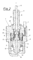
- the insulating body 8 In order to reduce the mass coupled to the force measuring element 6, according to the embodiment variant 2 of the insulating body 8 in a first facing the combustion chamber Part 14 and in a carrying the cable connection, held by a sealing shoulder 10 Part 15 shared.
- the inner electrode 9 is also made in two parts, the two Parts 19, 20 are electrically conductively connected by an elastic intermediate piece 16.
- the first part 14 of the insulating body 8 is supported axially with the interposition of the shape-matching part 11 from the force measuring element 6 on and off a shoulder 17 of the candle housing 2 held radially by the elastic membrane 13. Different requirements for the The heat value of the spark plug can be achieved by different positions of the membrane 13 , an alternative position being designated 13 '.
- the second part 15 of the Insulating body 8 is fixed in the candle housing 2.
- the force measuring element is used to reduce the mass coupled to the force measuring element 6 of the spark plug according to the invention in the axial direction between the first part 14 the two-part insulating body 8 and the candle housing 2 arranged so that the Insulated body 8 with the internal electrode 9 acted upon by the combustion chamber pressure with the interposition of the Force measuring element 6 is supported on the candle housing 2 or a shoulder 17 of the candle housing.
- the frictional connection between the insulating body 8 and candle housing 2 can on or arranged on both sides of the force measuring element 6 shape matching parts or Power transmission elements 11 take place, which the power flow between the uneven Ceramic surface of the insulating body 14 and the shoulder 17 of the candle housing and the Produce the machined surface of the measuring element 6.
- the signal line 7 shown only schematically in FIGS. 2 to 4 is preferably carried out together with the ignition cable, for example rotationally symmetrical to the ignition cable connection.
- the combustion chamber side Part 14 of the insulating body 8 with the inner electrode 19 is optimized for minimal mass.
- the second part 15 'of the insulating body is designed as a plug part of the ignition cable 21.
- the Inner electrode 20 'of the ignition cable which acts as a second part of the inner electrode 9 and the inner electrode 19 of the spark plug are via an elastic, electrically conductive element 16 connected, which can be designed screw or plug. As already shown in Fig. 3, this connection can also be designed as a free spark gap.
- a seal preferably an O-ring seal 22 may be provided, thereby providing adequate moisture protection is guaranteed.
- the signal line 7 is preferably in the plug part 15 'of the ignition cable 21 integrated.
Landscapes
- Chemical & Material Sciences (AREA)
- Engineering & Computer Science (AREA)
- Combustion & Propulsion (AREA)
- Physics & Mathematics (AREA)
- General Physics & Mathematics (AREA)
- Ignition Installations For Internal Combustion Engines (AREA)
- Spark Plugs (AREA)
- Measuring Fluid Pressure (AREA)
Description
Die Erfindung betrifft eine Zündkerze mit einem von einem Kerzengehäuse gehaltenen Isolierkörper mit einer Innenelektrode sowie mit einem Kraftmeßelement zur Messung des an der Zündkerze anliegenden Druckes, wobei sich der Isolierkörper bei Druckbeaufschlagung in axialer Richtung unter Zwischenlage des Kraftmeßelementes am Kerzengehäuse abstützt und zwischen dem Isolierkörper und dem Kerzengehäuse ein Radialspalt ausgebildet ist, wobei der Radialspalt brennraumseitig durch ein elastisches Dichtelement abgedichtet ist, welches zusätzlich zur Abstützung des Isolierkörpers am Kerzengehäuse dient.The invention relates to a spark plug with an insulating body held by a plug housing with an inner electrode and with a force measuring element for measurement of the pressure applied to the spark plug, the insulating body moving under pressure in the axial direction with the interposition of the force measuring element on the candle housing supports and a radial gap between the insulating body and the candle housing is formed, the radial gap on the combustion chamber side by an elastic sealing element is sealed, which also serves to support the insulating body on the candle housing.
Der Druck im Brennraum von Verbrennungskraftmaschinen ist die wesentliche Größe für die Beurteilung des Verbrennungsablaufes. Der Brennraumdruck muß daher häufig der Messung zugängig gemacht werden und stellt die ideale Basis für das Motormanagement bzw. für Motorregelungssysteme dar. Insbesondere im letztgenannten Anwendungsfall ist es wünschenswert, für die Druckmessung keine zusätzliche Bohrung im Brennraum vorsehen zu müssen. Eine Möglichkeit, diese zusätzliche Bohrung zu vermeiden besteht darin, eine Zündkerze zu verwenden, die eine Druckmeßfunktion aufweist.The pressure in the combustion chamber of internal combustion engines is the essential variable for the Assessment of the combustion process. The combustion chamber pressure must therefore often be measured be made accessible and provides the ideal basis for engine management and for Engine control systems. Especially in the latter application, it is desirable Do not provide an additional hole in the combustion chamber for pressure measurement have to. One way to avoid this additional drilling is to use a To use spark plug, which has a pressure measurement function.
Bekannte Vorrichtungen dieser Art können im wesentlichen in zwei Gruppen eingeteilt werden. Entweder wird ein sehr kleiner Drucksensor in den Kerzenkörper integriert, wobei im Zusammenhang mit der Kleinheit der Sensoren Fertigungsprobleme, Empfindlichkeit gegen Beschädigungen, große Meßfehler und die teure Herstellung anzuführen wären. Beispiele dafür sind aus der EP 0 441 157 A2 sowie aus der EP 0 581 067 A1 bekannt geworden.Known devices of this type can essentially be divided into two groups. Either a very small pressure sensor is integrated in the candle body, whereby in the Connection with the smallness of the sensors manufacturing problems, sensitivity to Damages, large measuring errors and the expensive production would have to be mentioned. Examples for this have become known from EP 0 441 157 A2 and from EP 0 581 067 A1.
Die zweite Gruppe verwendet sogenannte Kraftmeßscheiben, die anstelle einer Dichtung oder am Ort der Dichtung der Zündkerze eingebaut werden und die Änderung der Dichtkraft messen, die durch den Brennraumdruck verursacht wird. Zu dieser Gruppe gehören auch Zündkerzen, welche das Kraftmeßelement am Kerzengehäuse fixiert haben. Ein wesentlicher Nachteil dieser zweiten Gruppe liegt in der relativ großen Masse - nämlich die gesamte Kerzenmasse und ein wesentlicher Anteil des Zündkabels - welche vom Meßelement abzustützen sind. Neben geringer Eigenfrequenz des Systems werden dadurch vor allem große Störsignale bei Beschleunigung verursacht.The second group uses so-called force measuring disks, which instead of a seal or be installed at the location of the seal of the spark plug and the change in sealing force measure, which is caused by the combustion chamber pressure. This group also belongs Spark plugs, which have fixed the force measuring element to the spark plug housing. An essential one The disadvantage of this second group is the relatively large mass - namely the total candle mass and a substantial part of the ignition cable - which is supported by the measuring element are. In addition to the low natural frequency of the system, this results in large interference signals caused by acceleration.
Ein weiterer Nachteil besteht darin, daß sich das Kerzengehäuse sowie die Einschraubstelle der Zündkerze durch Temperaturunterschiede unterschiedlich verformen, wobei diese Verformungen unmittelbar auf das Kraftmeßelement wirken und große Meßfehler verursachen.Another disadvantage is that the candle housing and the screw point deform the spark plug differently due to temperature differences, these deformations act directly on the force measuring element and cause large measuring errors.
Aus der US-A 4 169 388 ist eine druckmessende Zündkerze bekannt, wobei sich das eigentliche piezoelektrische Kraftmeßelement zwischen einem ersten als Flansch ausgebildeten Teil des Gehäuses und einem zweiten, ringförmigen Teil des Gehäuses befindet. Der äußere Rand des Flansches ist über einen zylindrischen Dichtring mit dem Ring verschweißt. Als Nachteil bei dieser Bauform ist anzuführen, daß sich Verformungen des Flansches direkt auf das Meßelement auswirken und das Meßsignal beeinflussen. Weiters verteilen sich die zu messenden Gaskräfte auf das Gehäuse und das Meßelement, welche bezüglich der Krafteinwirkung parallel geschaltet sind. Dadurch wird als weiterer Nachteil die Signalhöhe verringert, da nur Teile der Gaskräfte auf das Meßelement einwirken. Weiters wirken auf das Meßelement größere, störende Massenkräfte, da neben dem Isolierkörper auch Teile des Gehäuses am Meßelement abgestützt sind.A pressure-measuring spark plug is known from US Pat. No. 4,169,388, the actual one Piezoelectric force measuring element between a first part designed as a flange of the housing and a second annular part of the housing. The outer edge the flange is welded to the ring via a cylindrical sealing ring. As a disadvantage in this design it should be noted that deformations of the flange directly on the Affect the measuring element and influence the measuring signal. Furthermore, the ones to be measured are distributed Gas forces on the housing and the measuring element, which relate to the force are connected in parallel. As a further disadvantage, the signal level is reduced because only parts of the gas forces act on the measuring element. Furthermore act on the measuring element Larger, disruptive mass forces, since in addition to the insulating body, parts of the housing on Measuring element are supported.
In der DE 31 30 238 A1 ist ein piezoelektrischer Wandler in das Gehäuse eines Anbauteiles der Brennkraftmaschine, vorzugsweise in eine Zündkerze, derart integriert, daß axial auf den Isolierkörper wirkende Kräfte in ein ringförmiges Kraftmeßelement eingeleitet werden, welches sich an einer Anformung des Gehäuses der Zündkerze abstützt. Nachteiligerweise liegt der brennraumseitige Teil des Isolierkörpers an einer inneren Schulter des Gehäuses der Zündkerze an und ist über diese Schulter vorgespannt, sodaß an dieser Stelle auch störende Axialkräfte eingeleitet werden können.DE 31 30 238 A1 describes a piezoelectric transducer in the housing of an attachment the internal combustion engine, preferably integrated into a spark plug, such that axially on the Insulating forces are introduced into an annular force measuring element, which is supported on a molding of the spark plug housing. Disadvantageously lies the combustion chamber side part of the insulating body on an inner shoulder of the housing Spark plug on and is biased over this shoulder, so that annoying at this point Axial forces can be initiated.
Aus der DE 656 168 A ist eine Zündkerze mit eingebauter piezoelektrischer Druckmeßeinrichtung bekannt. Der Isolierkörper der Zündkerze wird von einer Metallhülse umschlossen. welche fest mit einer Membran verbunden ist, die den Verbrennungsraum des Zylinders gegenüber dem Innenraum des Zündkerzengehäuses gasdicht abschließt. Die Metallhülse bildet eine Auflagefläche für einen Druckring, welcher auf den piezoelektrischen Kristall wirkt. Der zu messende Druck aus dem Verbrennungsraum wird mit Hilfe der Metallhülse auf die piezoelektrische Druckmeßeinrichtung übertragen, wobei diese Hülse gleichzeitig den Kristall gegen den Zündstrom elektrisch abschirmt.DE 656 168 A is a spark plug with a built-in piezoelectric pressure measuring device known. The insulating body of the spark plug is enclosed in a metal sleeve. which is firmly connected to a membrane that faces the combustion chamber of the cylinder seals the interior of the spark plug housing gas-tight. The metal sleeve forms a contact surface for a pressure ring, which acts on the piezoelectric crystal. The Pressure to be measured from the combustion chamber is applied to the piezoelectric using the metal sleeve Transfer pressure measuring device, this sleeve simultaneously the crystal shields electrically against the ignition current.
Eine Zündkerze der eingangs genannten Art ist beispielsweise aus der FR 1 212 282 A bekannt.
Zur Messung des an der Zündkerze anliegenden Druckes weist dieser ein im Kerzengehäuse
angeordnetes Kraftmeßelement auf, wobei sich der Isolierkörper der Innenelektrode
bei Druckbeaufschlagung in axialer Richtung unter Zwischenlage des Kraftmeßelementes am
Kerzengehäuse abstützt. Zwischen dem Isolierkörper und dem Kerzengehäuse ist ein Radialspalt
ausgebildet, welcher brennraumseitig durch ein elastisches Dichtelement abgedichtet
ist, welches zusätzlich zur Abstützung des Isolierkörpers am Kerzengehäuse dient. Auf das
Meßelement wirken allerdings störende Massenkräfte, bedingt durch die relativ große Masse
der Innenelektrode und des Isolierkörpers, ein.A spark plug of the type mentioned is known for example from
Aufgabe der vorliegenden Erfindung ist es, die genannten Nachteile zu vermeiden und eine Zündkerze mit Kraftmeßelement dahingehend zu verbessern, daß die Quellen für Störsignale vermieden werden bzw. deren Störpotential verringert wird.The object of the present invention is to avoid the disadvantages mentioned and one To improve the spark plug with force measuring element so that the sources of interference signals are avoided or their interference potential is reduced.
Diese Aufgabe wird erfindungsgemäß durch eine Zündkerze mit einem von einem Kerzengehäuse gehaltenen Isolierkörper mit einer Innenelektrode sowie mit einem Kraftmeßelement zur Messung des an der Zündkerze anliegenden Druckes gelöst, wobei der Isolierkörper samt Innenelektrode zweiteilig ausgeführt ist, die beiden Teile mechanisch weitgehend entkoppelt sind und sich der erste Teil des Isolierkörpers bei Druckbeaufschlagung in axialer Richtung unter Zwischenlage des Kraftmeßelementes am Kerzengehäuse abstützt und weiters zwischen dem ersten Teil des Isolierkörpers und dem Kerzengehäuse ein Radialspalt ausgebildet ist, wobei der Radialspalt brennraumseitig durch ein in axialer Richtung elastisches Dichtelement abgedichtet ist, welches zusätzlich zur Abstützung des Isolierkörpers am Kerzengehäuse dient, und wobei der zweite, kabelseitige Teil des Isolierkörpers im Kerzengehäuse gelagert oder abgestützt ist und zwischen den beiden Teilen der Innenelektrode ein elektrisch leitendes, elastisches Zwischenstück oder eine freie Funkenstrecke ausgebildet ist.According to the invention, this object is achieved by a spark plug with a spark plug housing held insulating body with an inner electrode and with a force measuring element to measure the pressure applied to the spark plug, the insulator is made in two parts together with the inner electrode, the two parts mechanically largely are decoupled and the first part of the insulating body when pressurized axially supported with the interposition of the force measuring element on the candle housing and furthermore a radial gap between the first part of the insulating body and the candle housing is formed, the radial gap on the combustion chamber side by an elastic in the axial direction Sealing element is sealed, which in addition to supporting the insulating body on Serves candle housing, and wherein the second, cable-side part of the insulating body in the candle housing is supported or supported and between the two parts of the inner electrode electrically conductive, elastic intermediate piece or a free spark gap is formed.
Zur Reduktion der am Kraftmeßelement angekoppelten Masse wird der Isolierkörper sowie die Innenelektrode geteilt, und zwar derart, daß der brennraumseitige Teil, der sich am Kraftmeßelement abstützt, nur noch eine Länge aufweist, die für die Erreichung des gewünschten Wärmewertes und der sicheren Fixierung der Innenelektrode nötig ist. Der für die kabelseitige, äußere Isolation nötige Teil des Isolierkörpers und der Kabelanschluß selbst werden unmittelbar am Gehäuse fixiert, sodaß deren Masse nicht auf das Kraftmeßelement einwirken kann. Damit ist die am Kraftmeßelement angekoppelte Masse auf einen Bruchteil reduziert; ebenso natürlich der daraus resultierende Meßfehler.To reduce the mass coupled to the force measuring element, the insulating body and the inner electrode divided, in such a way that the combustion chamber side part, which is on the force measuring element supports, only has a length that is sufficient to achieve the desired Heat value and the secure fixation of the inner electrode is necessary. The one for the cable side, External insulation necessary part of the insulating body and the cable connection itself become immediate fixed to the housing so that their mass does not affect the force measuring element can. The mass coupled to the force measuring element is thus reduced to a fraction; just as naturally the resulting measurement error.
Die Verbindung zwischen den beiden Teilen der Innenelektrode kann als elektrisch leitendes, elastisches Zwischenstück oder auch als freie Funkenstrecke ausgebildet sein.The connection between the two parts of the inner electrode can be an electrically conductive, elastic intermediate piece or be designed as a free spark gap.
Weiters ist vorgesehen, daß das elastische Dichtelement als kreisringförmige Membran ausgebildet ist. Eine derartige Membran hat ähnliche Eigenschaften wie bei herkömmlichen Drucksensoren, bei welchen das Gehäuse mit dem Druckübertragungskörper dicht aber elastisch verbunden wird. Das Zündkabel kann zumindest im Bereich des Anschlusses an die Innenelektrode massearm ausgeführt sein, wobei die Innenelektrode des Zündkabels nachgiebig, beispielsweise schlingenförmig oder als Wendel ausgeführt ist. Weitere Gewichtseinsparungen sind durch eine Optimierung des Isolators hinsichtlich Material und geringe Abmessungen erzielbar.It is also provided that the elastic sealing element as an annular membrane is trained. Such a membrane has properties similar to conventional ones Pressure sensors in which the housing with the pressure transmission body is tight but elastic is connected. The ignition cable can at least in the area of the connection to the Inner electrode be designed with low mass, the inner electrode of the ignition cable being flexible, for example loop-shaped or as a spiral. Further weight savings are by optimizing the insulator in terms of material and small dimensions achievable.
In einer Ausführungsvariante der Erfindung ist vorgesehen, daß der dem Brennraum zugewandte erste Teil des Isolierkörpers den brennraumseitigen Teil der Innenelektrode und der den Zündkabelanschluß enthaltende zweite Teil den kabelseitigen Teil der Innenelektrode aufweist, sowie daß eine elastische Isolierhülse vorgesehen ist, welche den Bereich zwischen den beiden Teilen des Isolierkörpers überbrückt.In an embodiment variant of the invention it is provided that the one facing the combustion chamber first part of the insulating body the combustion chamber side part of the inner electrode and the second part containing the ignition cable connection, the cable-side part of the inner electrode has, and that an elastic insulating sleeve is provided which covers the area between bridged the two parts of the insulating body.
In einer weiteren vorteilhaften Ausführung der Erfindung kann der Isolierkörper ebenfalls auf zwei weitgehend mechanisch entkoppelte Bereiche aufgeteilt werden. Erfindungsgemäß ist dabei vorgesehen, daß der dem Brennraum zugewandte erste Teil des Isolierkörpers den ersten Teil der Innenelektrode aufweist, und auf minimale Masse optimiert ist, sowie daß der zweite Teil des Isolierkörpers als Bestandteil des Zündkabels ausgeführt ist und den zweiten Teil der Innenelektrode aufweist.In a further advantageous embodiment of the invention, the insulating body can also be opened two largely mechanically decoupled areas can be divided. According to the invention provided that the first part of the insulating body facing the combustion chamber is the first Has part of the inner electrode, and is optimized for minimal mass, and that the second part of the insulating body is designed as part of the ignition cable and the second Has part of the inner electrode.
Auch hier ist es erfindungsgemäß möglich, die Verbindung zwischen der Innenelektrode und dem Zündkabel als elektrisch leitendes, elastisches Zwischenstück oder als freie Funkenstrecke auszubilden.Here, too, it is possible according to the invention to connect the inner electrode and the ignition cable as an electrically conductive, elastic intermediate piece or as a free spark gap to train.
Bei der zuletzt beschriebenen Ausführungsvariante übernimmt der kabelseitige Teil im wesentlichen die Funktion der sicheren Isolation am Übergang zum Zündkabel. Die in den Kabelstecker verlegten Teile des Isolierkörpers können wegen der hier relativ niedrigen Temperatur aus Kunststoff oder Gummi bestehen, was bereits eine weitgehende mechanische Entkopplung zum brennraumseitigen Teil des Isolierkörpers ergibt. Die Vorteile dieser Ausfühkopplung zum brennraumseitigen Teil des Isolierkörpers ergibt. Die Vorteile dieser Ausführung liegen einerseits in der geringen auf das Meßelement einwirkenden Masse, andererseits ist die Zündkerze selbst, die als Verschleißteil betrachtet werden muß, relativ billig herstellbar, wobei trotzdem gute Meßeigenschaften realisiert werden können.In the embodiment variant described last, the cable-side part essentially takes over the function of safe insulation at the transition to the ignition cable. The one in the cable connector Parts of the insulator can be misplaced due to the relatively low temperature here made of plastic or rubber, which is already a largely mechanical decoupling to the combustion chamber-side part of the insulating body. The advantages of this execution coupling to the combustion chamber-side part of the insulating body. The advantages of this version lie on the one hand in the low mass acting on the measuring element, on the other hand the spark plug itself, which must be regarded as a wearing part, can be manufactured relatively cheaply, good measuring properties can nevertheless be achieved.
Die Erfindung wird im folgenden anhand von Ausführungsbeispielen näher erläutert. Es zeigen Fig. 1 eine Zündkerze mit einem Kraftmeßelement nach dem Stand der Technik sowie Fig. 2 bis 4 erfindungsgemäße Ausführungsvarianten von derartigen Zündkerzen.The invention is explained in more detail below on the basis of exemplary embodiments. It 1 shows a spark plug with a force measuring element according to the prior art and 2 to 4 embodiment variants of such spark plugs according to the invention.
Die in Fig. 1 dargestellte bekannte Zündkerze 1 mit einer Druckmeßfunktion weist ein Kerzengehäuse
2 auf, welches mittels Außengewinde 3 in die Zündkerzenbohrung 4 eines nicht
näher dargestellten Zylinderkopfes einschraubbar ist. Im Bereich der Dichtschulter 5 des
Kerzengehäuses 2 ist ein Kraftmeßelement 6 angeordnet, welches axial wirkende Druckkräfte
in ein den Druckkräften proportionales elektrisches Signal umwandelt, welches über die
Signalleitung 7 abgegriffen werden kann. Das Kerzengehäuse 2 weist einen vorzugsweise
keramischen Isolierkörper 8 auf, welcher die Innenelektrode 9 aufnimmt.The known
Zwischen dem Teil 14 des Isolierkörpers 8 und dem Kerzengehäuse 2 ist in den erfindungsgemäßen
Ausführungsvarianten gemäß Fig. 2 bis 4 ein Radialspalt 12 ausgebildet, welcher
durch ein in axialer Richtung elastisches Dichtelement 13 gegenüber dem Brennraum abgedichtet
ist. Gleichzeitig kann das vorzugsweise als kreisringförmige Membran ausgebildete
Dichtelement 13 als radiale Abstützung des Isolierkörpers am Kerzengehäuse 2 dienen.Between the
Zur Verkleinerung der am Kraftmeßelement 6 angekoppelten Masse wird gemäß Ausführungsvariante
nach Fig. 2 der Isolierkörper 8 in einen dem Brennraum zugewandten ersten
Teil 14 und in einen den Kabelanschluß tragenden, von einer Dichtschulter 10 gehaltenen
Teil 15 geteilt. Die Innenelektrode 9 ist ebenfalls zweiteilig ausgeführt, wobei die beiden
Teile 19, 20 durch ein elastisches Zwischenstück 16 elektrisch leitend verbunden sind. Der
erste Teil 14 des Isolierkörpers 8 stützt sich axial unter Zwischenlage des Formanpassungsteiles
11 über das Kraftmeßelement 6 an einer Schulter 17 des Kerzengehäuses 2 ab und wird
radial durch die elastische Membran 13 gehalten. Unterschiedliche Anforderungen an den
Wärmewert der Zündkerze können durch unterschiedliche Lagen der Membran 13 realisiert
werden, wobei eine alternative Position mit 13' bezeichnet ist. Der zweite Teil 15 des
Isolierkörpers 8 ist fest im Kerzengehäuse 2 gelagert.In order to reduce the mass coupled to the
Im Bereich des elektrisch leitenden Zwischenstückes 16 der Innenelektrode 9 ist eine elektrische
Isolierhülse 18 angeordnet, welche den Bereich zwischen den beiden Teilen 14 und 15
des Isolierkörpers 8 überbrückt.In the area of the electrically conductive
Die Ausführungsvariante nach Fig. 3 entspricht weitgehend jener nach Fig. 2, wobei hier
durch die Ausbildung einer freien Funkenstrecke 16' eine vollständige mechanische Entkopplung
der beiden Teile 19 und 20 der Innenelektrode realisiert wird.3 largely corresponds to that of FIG. 2, with here
a complete mechanical decoupling by the formation of a free spark gap 16 '
of the two
Zur Verringerung der mit dem Kraftmeßelement gekoppelten Masse ist das Kraftmeßelement
6 der erfindungsgemäßen Zündkerze in axialer Richtung zwischen dem ersten Teil 14
des zweiteiligen Isolierkörpers 8 und dem Kerzengehäuse 2 angeordnet, sodaß sich der vom
Brennraumdruck beaufschlagte Isolierkörper 8 samt Innenelektrode 9 unter Zwischenlage des
Kraftmeßelementes 6 auf das Kerzengehäuse 2 bzw. eine Schulter 17 des Kerzengehäuses abstützt.
Der Kraftschluß zwischen Isolierkörper 8 und Kerzengehäuse 2 kann über an einer oder
an beiden Seiten des Kraftmeßelementes 6 angeordneten Formanpassungsteilen oder
Kraftübertragungselementen 11, erfolgen, welche den Kraftfluß zwischen der unebenen
Keramikfläche des Isolierkörpers 14 bzw. der Schulter 17 des Kerzengehäuses und der
bearbeiteten Fläche des Meßelementes 6 herstellen.The force measuring element is used to reduce the mass coupled to the
Die in den Fig. 2 bis 4 nur schematisch dargestellte Signalleitung 7 erfolgt bevorzugt zusammen
mit dem Zündkabel, beispielsweise rotationssymmetrisch zum Zündkabelanschluß.The
Die Ausführungsvariante nach Fig. 4 zeichnet sich dadurch aus, daß der brennraumseitige
Teil 14 des Isolierkörpers 8 mit der Innenelektrode 19 auf minimale Masse optimiert ist. Der
zweite Teil 15' des Isolierkörpers ist als Steckerteil des Zündkabels 21 ausgeführt. Die
Innenelektrode 20' des Zündkabels, welcher als zweiter Teil der Innenelektrode 9 fungiert und
die Innenelektrode 19 der Zündkerze sind über ein elastisches, elektrisch leitendes Element 16
verbunden, welches schraub- oder steckbar ausgeführt sein kann. Wie bereits in Fig. 3 dargestellt,
kann diese Verbindung auch als freie Vorfunkenstrecke ausgeführt sein. Zwischen dem
Steckerteil des Zündkabels 21 und dem Kerzengehäuse 2 kann eine Dichtung, vorzugsweise
eine O-Ringdichtung 22 vorgesehen sein, wodurch ein ausreichender Feuchtigkeitsschutz
garantiert wird. Die Signalleitung 7 wird vorzugsweise in den Steckerteil 15' des Zündkabels
21 integriert.4 is characterized in that the combustion
Claims (3)
- A spark plug comprising an insulating body 8 held in a spark plug shell 2 and including an inner electrode 9, and a force measuring element 6 measuring the pressure acting on the spark plug, wherein the insulating body 8 including the inner electrode 9 is configured in two parts (14, 15; 14, 15'), which are mechanically decoupled, and wherein the first part 14 of the insulating body 8 rests against the plug shell 2 via the force measuring element 6 when pressure is applied in axial direction, and a radial gap 12 is formed between the first part 14 of the insulating body 8 and the plug shell 2, and the radial gap 12 is sealed on the combustion chamber side by means of a radially elastic sealing element 13, 13', which is additionally used to hold the insulating body 8 in the plug shell 2, and wherein the second part 15, 15' of the insulating body 8 on the cable side is supported or held in the plug shell 2, and an electrically conductive, elastic intermediate piece 16 or a free spark gap 16' is provided between the two parts 19, 20; 19', 20' of the inner electrode 9.
- A spark plug according to Claim 1, wherein the first part 14 of the insulating body 8 adjacent to the combustion chamber includes the part 19 of the inner electrode 9 on the combustion chamber side, and the second part 15 containing the ignition cable connection includes the part 20 of the inner electrode 9 on the cable side, and wherein an elastic insulating sleeve 18 is provided for bridging the area between the two parts 14, 15 of the insulating body 8.
- A spark plug according to Claim 1, wherein the first part 14 of the insulating body 8 adjacent to the combustion chamber contains the first part 19 of the inner electrode 9 and is optimized to minimum mass, and wherein the second part 15' of the insulating body 8 is designed as part of the ignition cable 21 and contains the second part 20' of the inner electrode.
Applications Claiming Priority (3)
| Application Number | Priority Date | Filing Date | Title |
|---|---|---|---|
| AT0236394A AT402116B (en) | 1994-12-19 | 1994-12-19 | SPARK PLUG WITH A FORCE MEASUREMENT ELEMENT FOR MEASURING THE PRESSURE AT THE SPARK PLUG |
| AT236394 | 1994-12-19 | ||
| AT2363/94 | 1994-12-19 |
Publications (3)
| Publication Number | Publication Date |
|---|---|
| EP0718612A2 EP0718612A2 (en) | 1996-06-26 |
| EP0718612A3 EP0718612A3 (en) | 1996-12-04 |
| EP0718612B1 true EP0718612B1 (en) | 2000-02-09 |
Family
ID=3532969
Family Applications (1)
| Application Number | Title | Priority Date | Filing Date |
|---|---|---|---|
| EP95890218A Expired - Lifetime EP0718612B1 (en) | 1994-12-19 | 1995-12-12 | Spark plug with force measuring element and divided insulator |
Country Status (4)
| Country | Link |
|---|---|
| US (1) | US5726351A (en) |
| EP (1) | EP0718612B1 (en) |
| AT (1) | AT402116B (en) |
| DE (1) | DE59507784D1 (en) |
Cited By (1)
| Publication number | Priority date | Publication date | Assignee | Title |
|---|---|---|---|---|
| DE102010037476A1 (en) * | 2010-09-10 | 2012-03-15 | Borgwarner Beru Systems Gmbh | Pressure gauge for measuring pressure in combustion chamber of engine e.g. diesel engine, of motor car, has diaphragm arranged between sensor and housing membrane and generating restoring force based on axial displacement of heating rod |
Families Citing this family (22)
| Publication number | Priority date | Publication date | Assignee | Title |
|---|---|---|---|---|
| US6094990A (en) * | 1998-06-30 | 2000-08-01 | Cooper Automotive Products, Inc. | Spark plug with concentric pressure sensor |
| AT407577B (en) | 1999-08-05 | 2001-04-25 | Avl List Gmbh | SPARK PLUG WITH A PRESSURE MEASURING DEVICE |
| EP1486653B1 (en) * | 2003-06-12 | 2016-04-13 | Denso Corporation | Combustion pressure sensor |
| DE102004024341B3 (en) * | 2004-05-17 | 2005-12-22 | Beru Ag | pressure measuring glow |
| ES2384389T3 (en) * | 2004-09-22 | 2012-07-04 | Kistler Holding Ag | Pressure sensor |
| DE102004063749A1 (en) * | 2004-12-29 | 2006-07-13 | Robert Bosch Gmbh | Steel diaphragm for combustion chamber pressure sensors |
| DE102005025115A1 (en) * | 2005-06-01 | 2006-12-07 | Robert Bosch Gmbh | Integrated combustion chamber pressure sensor |
| DE102005050502B3 (en) * | 2005-10-21 | 2007-04-05 | Giese, Erhard, Dr. | Glow plug for combustion chamber of diesel engine, has pressure sensor provided with pressure membrane and arranged in central borehole of screw-in housing, and connection-unit for electrical connection of glow body and arranged in chamber |
| AT503662B1 (en) | 2006-04-20 | 2007-12-15 | Piezocryst Advanced Sensorics | GLOW PLUG WITH INTEGRATED PRESSURE SENSOR |
| AT503067B1 (en) | 2007-03-08 | 2008-08-15 | Avl List Gmbh | Spark plug for internal combustion engine, has housing with borehole for accommodating fiber-optic light guide that opens out into combustion chamber, where axis of borehole runs inclined to axis of other borehole in housing |
| DE102008020510B4 (en) * | 2008-04-23 | 2010-02-11 | Beru Ag | Apparatus and method for determining the combustion chamber pressure |
| DE102008020509B4 (en) * | 2008-04-23 | 2010-02-25 | Beru Ag | Method for producing a device for determining the combustion chamber pressure and such a device |
| AT505077B1 (en) | 2008-06-06 | 2010-01-15 | Avl List Gmbh | MEASURING DEVICE |
| CH699078A1 (en) * | 2008-07-02 | 2010-01-15 | Kistler Holding Ag | Spark plug in basic structure with pressure sensor. |
| DE102008042645A1 (en) * | 2008-10-07 | 2010-04-08 | Robert Bosch Gmbh | Combustion chamber pressure sensor |
| KR20110119761A (en) * | 2009-01-29 | 2011-11-02 | 페더럴-모굴 이그니션 컴퍼니 | Spark plug with integral combustion sensor and engine component therewith |
| CN102341979A (en) * | 2009-01-29 | 2012-02-01 | 费德罗-莫格尔点火公司 | Spark plug with combustion sensor |
| FR2955215B1 (en) * | 2010-01-08 | 2012-03-30 | Continental Automotive France | IGNITION CANDLE COMPRISING A CYLINDER PRESSURE SENSOR AND A CLICK DETECTOR |
| DE102010011739B4 (en) * | 2010-03-17 | 2014-12-18 | Federal-Mogul Ignition Gmbh | Spark plug and method of making a spark plug |
| US8857249B2 (en) | 2011-08-22 | 2014-10-14 | BorgWarner BERU Systems, GmbH | Dual diaphragm combustion pressure measuring device |
| JP6408844B2 (en) * | 2013-10-25 | 2018-10-17 | 日本特殊陶業株式会社 | Combustion pressure sensor, glow plug combined combustion pressure sensor, combustion pressure sensor manufacturing method, and glow plug combined combustion pressure sensor manufacturing method |
| DE102018105182B4 (en) * | 2018-03-07 | 2021-06-10 | SparkX GmbH | Chamber candle with piezo pressure sensor |
Citations (1)
| Publication number | Priority date | Publication date | Assignee | Title |
|---|---|---|---|---|
| DE3130238A1 (en) * | 1981-07-31 | 1983-02-17 | Daimler-Benz Ag, 7000 Stuttgart | Pressure sensor for internal-combustion engines |
Family Cites Families (11)
| Publication number | Priority date | Publication date | Assignee | Title |
|---|---|---|---|---|
| DE656168C (en) * | 1932-04-16 | 1938-01-31 | Loewe Opta Gmbh | Spark plug with built-in piezoelectric pressure measuring device |
| FR1212282A (en) * | 1957-10-01 | 1960-03-23 | Bruce Peebles & Co Ltd | Combined spark plug with pressure transmitter sensor for testing internal combustion engines |
| US4169388A (en) * | 1978-12-13 | 1979-10-02 | The Bendix Corporation | Integrated spark plug-combustion pressure sensor |
| DE3001711A1 (en) * | 1980-01-18 | 1981-07-23 | Robert Bosch Gmbh, 7000 Stuttgart | Combustion engine knock vibration sensor - has optical conductor built into spark plug electrode and connected to photocell |
| US4602506A (en) * | 1984-06-29 | 1986-07-29 | Nissan Motor Co., Ltd. | Combustion pressure sensor arrangement |
| DE3514597A1 (en) * | 1985-04-23 | 1986-10-30 | Robert Bosch Gmbh, 7000 Stuttgart | SPARK PLUG WITH A PRESSURE MEASURING DEVICE |
| JPH01134392U (en) * | 1988-03-07 | 1989-09-13 | ||
| JPH03216983A (en) * | 1990-01-22 | 1991-09-24 | Nippondenso Co Ltd | Ignition plug with pressure detector |
| JPH03293534A (en) * | 1990-04-12 | 1991-12-25 | Nissan Motor Co Ltd | Mounting apparatus for pressure sensor |
| DE4022782A1 (en) * | 1990-07-18 | 1992-01-23 | Bosch Gmbh Robert | PRESSURE SENSOR FOR DETECTING PRINTERS IN THE COMBUSTION CHAMBER OF COMBUSTION ENGINES |
| JP3141218B2 (en) * | 1992-07-28 | 2001-03-05 | 日本特殊陶業株式会社 | Spark plug with built-in pressure sensor |
-
1994
- 1994-12-19 AT AT0236394A patent/AT402116B/en not_active IP Right Cessation
-
1995
- 1995-12-12 EP EP95890218A patent/EP0718612B1/en not_active Expired - Lifetime
- 1995-12-12 DE DE59507784T patent/DE59507784D1/en not_active Expired - Lifetime
- 1995-12-18 US US08/574,219 patent/US5726351A/en not_active Expired - Lifetime
Patent Citations (1)
| Publication number | Priority date | Publication date | Assignee | Title |
|---|---|---|---|---|
| DE3130238A1 (en) * | 1981-07-31 | 1983-02-17 | Daimler-Benz Ag, 7000 Stuttgart | Pressure sensor for internal-combustion engines |
Cited By (2)
| Publication number | Priority date | Publication date | Assignee | Title |
|---|---|---|---|---|
| DE102010037476A1 (en) * | 2010-09-10 | 2012-03-15 | Borgwarner Beru Systems Gmbh | Pressure gauge for measuring pressure in combustion chamber of engine e.g. diesel engine, of motor car, has diaphragm arranged between sensor and housing membrane and generating restoring force based on axial displacement of heating rod |
| DE102010037476B4 (en) * | 2010-09-10 | 2012-04-26 | Borgwarner Beru Systems Gmbh | pressure monitor |
Also Published As
| Publication number | Publication date |
|---|---|
| EP0718612A3 (en) | 1996-12-04 |
| AT402116B (en) | 1997-02-25 |
| EP0718612A2 (en) | 1996-06-26 |
| ATA236394A (en) | 1996-06-15 |
| US5726351A (en) | 1998-03-10 |
| DE59507784D1 (en) | 2000-03-16 |
Similar Documents
| Publication | Publication Date | Title |
|---|---|---|
| EP0718612B1 (en) | Spark plug with force measuring element and divided insulator | |
| DE69111337T2 (en) | Pressure gauge. | |
| EP1989485B1 (en) | Pressure measuring device | |
| EP1517086B1 (en) | Glow Plug with a pressure sensor for a diesel engine | |
| EP1847777B1 (en) | Glow plug with integrated pressure sensor | |
| DE2906407C2 (en) | Piezoelectric transducer element for installation in pressure, force or acceleration sensors | |
| DE4111869C2 (en) | ||
| DE3838333A1 (en) | CAPACITY GAUGE WITH RELAXATION OF THE FIXED ELECTRODE | |
| EP1074828B1 (en) | Spark plug with pressure measuring device | |
| EP1409979A1 (en) | Pressure sensor | |
| DE102005051817A1 (en) | Pressure measuring heating element, in particular for a Druckmessglühkerze | |
| WO2015090757A1 (en) | Pressure sensor | |
| EP0140066A1 (en) | Device for detecting forces, tensions or accelerations at machines, apparatuses or the like | |
| DE19608321A1 (en) | Differential pressure transmitter unit with an overload protection system | |
| EP1967834B1 (en) | Ignition plug with a pressure sensing device | |
| WO2012016811A1 (en) | Apparatus for sensing a combustion chamber pressure in an internal combustion engine | |
| EP0995979B1 (en) | Pressure sensor | |
| EP1792156B1 (en) | Device for detecting the pressure prevailing in a combustion chamber of an internal combustion engine | |
| WO1987000128A1 (en) | Pressure sensor | |
| DE69405788T2 (en) | Spark plug with built-in pressure sensor | |
| EP1631804A1 (en) | Moisture-protected pressure sensor | |
| WO1998023949A1 (en) | Gas sensor | |
| EP0548043B1 (en) | Pressure sensor | |
| EP0226742A2 (en) | Pressure transducer for measuring pressures at high temperatures | |
| WO2001023855A2 (en) | Pressure sensor |
Legal Events
| Date | Code | Title | Description |
|---|---|---|---|
| PUAI | Public reference made under article 153(3) epc to a published international application that has entered the european phase |
Free format text: ORIGINAL CODE: 0009012 |
|
| AK | Designated contracting states |
Kind code of ref document: A2 Designated state(s): CH DE ES FR GB IT LI |
|
| PUAL | Search report despatched |
Free format text: ORIGINAL CODE: 0009013 |
|
| AK | Designated contracting states |
Kind code of ref document: A3 Designated state(s): CH DE ES FR GB IT LI |
|
| RAP1 | Party data changed (applicant data changed or rights of an application transferred) |
Owner name: AVL LIST GMBH |
|
| 17P | Request for examination filed |
Effective date: 19970310 |
|
| 17Q | First examination report despatched |
Effective date: 19980309 |
|
| RTI1 | Title (correction) |
Free format text: SPARK PLUG WITH FORCE MEASURING ELEMENT AND DIVIDED INSULATOR |
|
| GRAG | Despatch of communication of intention to grant |
Free format text: ORIGINAL CODE: EPIDOS AGRA |
|
| GRAG | Despatch of communication of intention to grant |
Free format text: ORIGINAL CODE: EPIDOS AGRA |
|
| GRAH | Despatch of communication of intention to grant a patent |
Free format text: ORIGINAL CODE: EPIDOS IGRA |
|
| RTI1 | Title (correction) |
Free format text: SPARK PLUG WITH FORCE MEASURING ELEMENT AND DIVIDED INSULATOR |
|
| GRAH | Despatch of communication of intention to grant a patent |
Free format text: ORIGINAL CODE: EPIDOS IGRA |
|
| GRAA | (expected) grant |
Free format text: ORIGINAL CODE: 0009210 |
|
| AK | Designated contracting states |
Kind code of ref document: B1 Designated state(s): CH DE ES FR GB IT LI |
|
| PG25 | Lapsed in a contracting state [announced via postgrant information from national office to epo] |
Ref country code: ES Free format text: THE PATENT HAS BEEN ANNULLED BY A DECISION OF A NATIONAL AUTHORITY Effective date: 20000209 |
|
| REG | Reference to a national code |
Ref country code: CH Ref legal event code: EP |
|
| GBT | Gb: translation of ep patent filed (gb section 77(6)(a)/1977) |
Effective date: 20000209 |
|
| REF | Corresponds to: |
Ref document number: 59507784 Country of ref document: DE Date of ref document: 20000316 |
|
| ET | Fr: translation filed | ||
| GBT | Gb: translation of ep patent filed (gb section 77(6)(a)/1977) |
Free format text: ERRATUM: THE FOLLOWING EUROPEAN PATENTS WERE ADVERTISED IN ERROR IN JOURNAL 5781 DATED 1 MARCH 2000 AS HAVING BEEN FILED UNDER SECTION 77(6)(A) ON 8 FEBRUARY 2000. |
|
| ITF | It: translation for a ep patent filed | ||
| PLBE | No opposition filed within time limit |
Free format text: ORIGINAL CODE: 0009261 |
|
| STAA | Information on the status of an ep patent application or granted ep patent |
Free format text: STATUS: NO OPPOSITION FILED WITHIN TIME LIMIT |
|
| PG25 | Lapsed in a contracting state [announced via postgrant information from national office to epo] |
Ref country code: LI Free format text: LAPSE BECAUSE OF NON-PAYMENT OF DUE FEES Effective date: 20001231 Ref country code: CH Free format text: LAPSE BECAUSE OF NON-PAYMENT OF DUE FEES Effective date: 20001231 |
|
| 26N | No opposition filed | ||
| REG | Reference to a national code |
Ref country code: CH Ref legal event code: PL |
|
| REG | Reference to a national code |
Ref country code: GB Ref legal event code: IF02 |
|
| PGFP | Annual fee paid to national office [announced via postgrant information from national office to epo] |
Ref country code: GB Payment date: 20051201 Year of fee payment: 11 |
|
| PGFP | Annual fee paid to national office [announced via postgrant information from national office to epo] |
Ref country code: FR Payment date: 20051222 Year of fee payment: 11 |
|
| REG | Reference to a national code |
Ref country code: GB Ref legal event code: 732E |
|
| REG | Reference to a national code |
Ref country code: FR Ref legal event code: TP |
|
| PGFP | Annual fee paid to national office [announced via postgrant information from national office to epo] |
Ref country code: IT Payment date: 20061231 Year of fee payment: 12 |
|
| GBPC | Gb: european patent ceased through non-payment of renewal fee |
Effective date: 20061212 |
|
| REG | Reference to a national code |
Ref country code: FR Ref legal event code: ST Effective date: 20070831 |
|
| PG25 | Lapsed in a contracting state [announced via postgrant information from national office to epo] |
Ref country code: GB Free format text: LAPSE BECAUSE OF NON-PAYMENT OF DUE FEES Effective date: 20061212 |
|
| PG25 | Lapsed in a contracting state [announced via postgrant information from national office to epo] |
Ref country code: FR Free format text: LAPSE BECAUSE OF NON-PAYMENT OF DUE FEES Effective date: 20070102 |
|
| PG25 | Lapsed in a contracting state [announced via postgrant information from national office to epo] |
Ref country code: IT Free format text: LAPSE BECAUSE OF NON-PAYMENT OF DUE FEES Effective date: 20071212 |
|
| PGFP | Annual fee paid to national office [announced via postgrant information from national office to epo] |
Ref country code: DE Payment date: 20111230 Year of fee payment: 17 |
|
| REG | Reference to a national code |
Ref country code: DE Ref legal event code: R119 Ref document number: 59507784 Country of ref document: DE Effective date: 20130702 |
|
| PG25 | Lapsed in a contracting state [announced via postgrant information from national office to epo] |
Ref country code: DE Free format text: LAPSE BECAUSE OF NON-PAYMENT OF DUE FEES Effective date: 20130702 |