EP0716977A1 - Heckschraube für ein Boot - Google Patents
Heckschraube für ein Boot Download PDFInfo
- Publication number
- EP0716977A1 EP0716977A1 EP95203463A EP95203463A EP0716977A1 EP 0716977 A1 EP0716977 A1 EP 0716977A1 EP 95203463 A EP95203463 A EP 95203463A EP 95203463 A EP95203463 A EP 95203463A EP 0716977 A1 EP0716977 A1 EP 0716977A1
- Authority
- EP
- European Patent Office
- Prior art keywords
- stern
- tunnel tube
- boat
- screw
- propeller
- Prior art date
- Legal status (The legal status is an assumption and is not a legal conclusion. Google has not performed a legal analysis and makes no representation as to the accuracy of the status listed.)
- Granted
Links
Images

Classifications
-
- B—PERFORMING OPERATIONS; TRANSPORTING
- B63—SHIPS OR OTHER WATERBORNE VESSELS; RELATED EQUIPMENT
- B63H—MARINE PROPULSION OR STEERING
- B63H5/00—Arrangements on vessels of propulsion elements directly acting on water
- B63H5/07—Arrangements on vessels of propulsion elements directly acting on water of propellers
- B63H5/14—Arrangements on vessels of propulsion elements directly acting on water of propellers characterised by being mounted in non-rotating ducts or rings, e.g. adjustable for steering purpose
Definitions
- the invention relates to a stern screw for a boat comprising a tunnel tube in which a propeller is provided with rotation possibility about a shaft, which propeller is driven by a drive motor at least during operation.
- a stern screw is arranged at the rear side, or stern, of a boat and provides a propulsion of the boat transverse to its longitudinal direction.
- the boat can thus be manoeuvred much more easily than a boat provided solely with a main screw for forward propulsion, in which case manoeuvring is effected by means of the rudder only.
- a known stern screw is incorporated in a completely watertight housing of stainless steel which is mounted against the rear side or stern of the boat.
- Said housing comprises on the one hand the tunnel tube, but on the other hand also the drive motor and must on that account project partly above the water line. This is not only visually unattractive, but it also hampers the placement of a swimming platform.
- the manufacture of such a housing which is often bulky, is comparatively expensive because the housing must be made entirely of corrosion-resistent material (stainless steel) and must be continually tested for leakproofness. Owing to the leakproofness of the housing, moreover, virtually no ventilation will be possible therein, so that any condensation cannot be removed, which may lead to corrosion after all in the long run.
- the present invention has for its object inter alia to provide a stern screw of the kind mentioned in the opening paragraph in which said disadvantages and drawbacks are counteracted.
- a stern screw of the kind mentioned in the opening paragraph is for this purpose characterized in that the tunnel tube comprises an opening for receiving therein an intermediate part, in that the intermediate part is profiled at a first side for forming a portion of the inner wall of the tube and is provided with a flange at a second side for fastening to an outer side of a stern of the boat, and in that the intermediate part comprises a cavity in which a drive shaft is accommodated which is coupled to the propeller at one side and to the drive motor at the other side, said drive motor being placed at an inner side of the stern.
- the entire stern screw may be provided below the water line so that the presence of the stern screw no longer forms an obstacle to the placement of a swimming platform and is no longer visually unattractive.
- the intermediate part ensures, possibly in combination with a suitable gasket, a watertight mounting of the tunnel tube with the propeller inside against the stern of the boat.
- the drive motor of the stern screw according to the invention is present in its entirety inside the boat and is accordingly always accessible for maintenance while requiring no special anti-corrosion measures.
- the tunnel tube thereof in a preferred embodiment of the stern screw according to the invention comprises flared ends.
- the inlet and outlet openings of the tunnel tube are widened thereby, so that more water can be displaced.
- An optimum propelling force is found to be achieved here in a special embodiment wherein the flared ends each terminate in a flange which extends transversely to the longitudinal direction of the tunnel tube.
- Such a stern screw has proved itself capable of providing a particularly great propelling force in practice.
- the drive motor is detachably mounted to a side of the intermediate part which faces away from the tunnel tube.
- a so-called shear pin shear link
- the drive shaft may be readily revised in the case of jamming of the propeller now without the necessity of taking the boat from the water.
- the tunnel tube may be made from any suitable material, but it preferably comprises a corrosion-resistent material such as stainless steel, aluminium or synthetic resin. Any remaining, less corrosion-resistent metal parts in the water side of the stern screw are preferably provided with a zinc anode for protection against corrosion.
- a corrosion-resistent material such as stainless steel, aluminium or synthetic resin. Any remaining, less corrosion-resistent metal parts in the water side of the stern screw are preferably provided with a zinc anode for protection against corrosion.
- the stern screw according to the invention preferably comprises a specially shaped propeller with a substantially symmetrical propulsion characteristic in relation to its direction of rotation.
- the propelling force of the stern screw is then substantially the same in clockwise and anti-clockwise direction.
- the invention further relates to a boat provided with a stern screw according to the invention, which boat according to the invention is characterized in that the stern screw is placed against the stern of the boat such that a centreline of the tunnel tube is at least half a tunnel tube diameter above the bottom of the boat and at least a full tunnel tube diameter below the water line. It is found in practice that a stern screw at this minimum depth below the water line has the highest efficiency while its positioning above the bottom of the boat influences the hydrodynamic resistance of the boat as little as possible, so that speed losses are reduced to a minimum.
- Fig. 1 shows the rear of a boat, for example a yacht or motor vessel, provided with a stern screw according to the invention which is mounted against the stern 4 of the boat.
- the stern of the boat can be moved to starboard or port by means of the stern screw, also when the boat lies almost or completely still, whereby manoeuvring of the boat is made much easier.
- a similar effect can be achieved at the bow through the use of a bow screw.
- the stern screw comprises a tunnel tube 5 in which a propeller 7 is mounted with rotation possibility about a shaft which is coupled via a dog 6 to an electric drive motor 3 provided with a switch-on relay.
- a centreline 20 of the tunnel tube lies at least one half tunnel tube diameter d above the bottom 11 of the boat and at least one full tunnel tube diameter below the water line WL.
- the entire stern screw is now hidden from view so that it does not detract from the boat's appearance, unlike the known rotor. Since the stern screw does not project below the ship in this embodiment, the hydrodynamic resistance, and consequently the speed of the boat are hardly influenced by the presence of the stern screw.
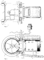
- FIG. 3 is a second cross-sectional view taken in a plane perpendicular to that of the cross-section of Fig. 2.
- the entire drive motor 3 is placed inside the boat here, while the tunnel tube 5 with the dog 6 and propeller 7 are arranged at the water side of the stern 4.
- the tunnel tube 5 according to the invention is provided with an opening 21 for receiving therein an intermediate part 8 to realize such a construction.
- the intermediate part 8 has a concave round profile at a first side 81, thus forming part of an inner wall of the tunnel tube, while comprising a flange 82 at the other side by means of which the intermediate part itself together with the tunnel tube 5, dog 6, and propeller 7 is fastened to the water side of the stern.
- a number of bores is circumferentially provided in the flange and the stern, so that the intermediate part can be mounted with a corresponding number of bolts 23 and nuts 24.
- a suitable gasket may be interposed between the flange 82 and the stern 4 to ensure watertightness.
- the dog 6 with propeller 7 and tunnel tube 5 are fastened to the intermediate part.
- the intermediate part further comprises a number of zinc anodes at the water side for protecting the part against corrosion.
- Such an anode 10 is also present on the metal dog 6.
- the propeller itself is made from synthetic resin and is thus corrosion-resistent.
- a special propeller shape is used in this embodiment with an at least substantially symmetrical propulsion characteristic in relation to the direction of rotation.
- the stern screw as a result has a substantially identical steering behaviour to starboard and port.
- the electric motor 3 is fastened to the inside of the stern 4 and is detachably connected to the external parts of the stern screw by means of nuts and bolts via an interposed flange 9 which is passed through an opening in the stern 4.
- the intermediate part 8 and the interposed flange 9 enclose a central cavity in which the output shaft of the electric motor is accommodated and coupled to the propeller 7 via dog 6.
- a support 13 is provided below the electric motor 3 to bear the usually considerable weight thereof and thus take the load off the stern screw.
- the tunnel tube 5 in this embodiment is of a special shape, i.e. its ends are flared out and terminate each in a flange 25 which extends transversely to the longitudinal direction of the tube 5.
- a flared shape at the ends of the tunnel tube widens the effective inlet and outlet openings, which increases the efficiency, and a considerable propelling force is achieved even with a comparatively short tunnel tube.
- the length of the tunnel tube 5 is such, moreover, that the water flow path length inside the tunnel tube 5 is practically ideal. A gain in propelling force of 40-50% was achieved in practice with a tunnel tube 5 of this shape.
- the tunnel tube may be moulded/cast, for example, from synthetic resin, such as polyester, or from aluminium, whereby the desired shape may be readily realized.
- the tunnel tube is not only corrosion-resistent owing to the use of said materials but also comparatively light in weight.
- tunnel tube 5 increases the efficiency of the stern screw by some 20%, it also provides the propeller with an adequate screening.
- a rotating propeller would otherwise form a major injury risk for a swimmer or someone who had inadvertently fallen overboard if his/her limbs, for example, were to come into contact with the propeller.
- the tube dampens the noise of the propeller.
- the invention offers a particularly powerful stern screw and a boat provided therewith whose outward appearance is not impaired by the presence of the rotor, while the latter in addition does not present an obstacle to the placement of a swimming platform or something similar at the rear of the boat.
Landscapes
- Chemical & Material Sciences (AREA)
- Engineering & Computer Science (AREA)
- Combustion & Propulsion (AREA)
- Mechanical Engineering (AREA)
- Ocean & Marine Engineering (AREA)
- Prevention Of Electric Corrosion (AREA)
- Toys (AREA)
- Removal Of Floating Material (AREA)
- Lining And Supports For Tunnels (AREA)
- Catching Or Destruction (AREA)
- Stopping Of Electric Motors (AREA)
- Dowels (AREA)
- Curing Cements, Concrete, And Artificial Stone (AREA)
Applications Claiming Priority (2)
| Application Number | Priority Date | Filing Date | Title |
|---|---|---|---|
| NL9402140 | 1994-12-16 | ||
| NL9402140 | 1994-12-16 |
Publications (2)
| Publication Number | Publication Date |
|---|---|
| EP0716977A1 true EP0716977A1 (de) | 1996-06-19 |
| EP0716977B1 EP0716977B1 (de) | 1999-08-04 |
Family
ID=19865027
Family Applications (1)
| Application Number | Title | Priority Date | Filing Date |
|---|---|---|---|
| EP95203463A Expired - Lifetime EP0716977B1 (de) | 1994-12-16 | 1995-12-13 | Heckschraube für ein Boot |
Country Status (5)
| Country | Link |
|---|---|
| US (1) | US5704306A (de) |
| EP (1) | EP0716977B1 (de) |
| AT (1) | ATE182851T1 (de) |
| DE (1) | DE69511227D1 (de) |
| NO (1) | NO305647B1 (de) |
Cited By (3)
| Publication number | Priority date | Publication date | Assignee | Title |
|---|---|---|---|---|
| WO2005087584A1 (de) | 2004-03-15 | 2005-09-22 | Hubert Holesz | Bugstrahlruder für aussenmontage |
| WO2008108664A1 (en) * | 2007-03-08 | 2008-09-12 | Sleipner Motor As | Stern thruster |
| US8939104B2 (en) | 2008-11-17 | 2015-01-27 | Sleipner—Marinno GmbH | Lateral thruster for a vessel |
Families Citing this family (13)
| Publication number | Priority date | Publication date | Assignee | Title |
|---|---|---|---|---|
| US6579133B1 (en) | 2002-06-06 | 2003-06-17 | Bill Harris | Boat positioning apparatus and system |
| CA2419669A1 (en) | 2002-12-06 | 2004-06-06 | Cap Sante Marine, Ltd. | Boat thruster apparatus and method |
| US6964590B1 (en) * | 2004-11-06 | 2005-11-15 | Don Dongcho Ha | Lateral thrust drive unit for marine vessels |
| CH705329A2 (de) * | 2011-07-16 | 2013-01-31 | Peter A Mueller | Manövrieranlage für Wasserfahrzeuge. |
| US9399183B2 (en) | 2014-04-01 | 2016-07-26 | Dometic Corporation | Vent filter |
| US10782690B1 (en) * | 2017-08-31 | 2020-09-22 | Correct Craft Ip Holdings, Llc | Thruster system for marine vessels |
| US11383815B1 (en) | 2017-08-31 | 2022-07-12 | Correct Craft Ip Holdings, Llc | Thruster system for marine vessels |
| CA3012297A1 (en) * | 2018-07-25 | 2020-01-25 | Sideshift Inc. | Stern-mounted lateral marine thruster |
| US11220318B2 (en) * | 2020-04-09 | 2022-01-11 | The Yacht Group Llc | Bracket for mounting a thruster to a boat |
| US11718380B2 (en) | 2020-04-09 | 2023-08-08 | The Yacht Group Llc | Bracket for mounting a thruster to a boat |
| US11396355B2 (en) * | 2020-04-09 | 2022-07-26 | The Yacht Group, LLC | Bracket for mounting a thruster to a boat |
| USD971119S1 (en) * | 2020-06-15 | 2022-11-29 | Gerald Berton | Bracket for mounting a thruster to a boat |
| EP3975393A1 (de) * | 2020-09-28 | 2022-03-30 | Iordanov Nakev Plamen | Antriebseinheit für ein querstrahlruder und querstrahlruder mit solch einer antriebseinheit |
Citations (6)
| Publication number | Priority date | Publication date | Assignee | Title |
|---|---|---|---|---|
| US2997015A (en) * | 1960-07-25 | 1961-08-22 | Harvey E Richter | Marine propulsion device |
| FR1514519A (fr) * | 1966-03-12 | 1968-02-23 | Porsche Kg | Groupe propulseur pour bateaux ou engins équivalents |
| US3487805A (en) * | 1966-12-22 | 1970-01-06 | Satterthwaite James G | Peripheral journal propeller drive |
| US3792938A (en) * | 1973-01-26 | 1974-02-19 | Production Mold Inc | Propeller nut and fairwater |
| US4789302A (en) * | 1987-02-06 | 1988-12-06 | Josip Gruzling | Propeller shroud |
| DE3935754A1 (de) * | 1989-10-27 | 1991-05-02 | Telefunken Systemtechnik | Vortriebsvorrichtung fuer wasserfahrzeuge, schwimmende bauwerke u. dgl. |
Family Cites Families (5)
| Publication number | Priority date | Publication date | Assignee | Title |
|---|---|---|---|---|
| US3127865A (en) * | 1960-12-23 | 1964-04-07 | Pleuger Friedrich Wilhelm | Propulsion units for watercraft |
| US3593686A (en) * | 1969-08-28 | 1971-07-20 | Euvon G Cooper | System for laterally maneuvering a watercraft hull |
| US4208978A (en) * | 1978-12-18 | 1980-06-24 | Eller James D | Lateral thruster for a water vessel |
| DE3460525D1 (en) * | 1983-02-04 | 1986-10-02 | Brunvoll Motorfab | Elastically supported thruster structure |
| US5140926A (en) * | 1991-07-05 | 1992-08-25 | Lawrence Denston | Small boat thruster kit |
-
1995
- 1995-12-13 AT AT95203463T patent/ATE182851T1/de not_active IP Right Cessation
- 1995-12-13 EP EP95203463A patent/EP0716977B1/de not_active Expired - Lifetime
- 1995-12-13 DE DE69511227T patent/DE69511227D1/de not_active Expired - Lifetime
- 1995-12-15 NO NO955096A patent/NO305647B1/no not_active IP Right Cessation
- 1995-12-15 US US08/573,037 patent/US5704306A/en not_active Expired - Fee Related
Patent Citations (6)
| Publication number | Priority date | Publication date | Assignee | Title |
|---|---|---|---|---|
| US2997015A (en) * | 1960-07-25 | 1961-08-22 | Harvey E Richter | Marine propulsion device |
| FR1514519A (fr) * | 1966-03-12 | 1968-02-23 | Porsche Kg | Groupe propulseur pour bateaux ou engins équivalents |
| US3487805A (en) * | 1966-12-22 | 1970-01-06 | Satterthwaite James G | Peripheral journal propeller drive |
| US3792938A (en) * | 1973-01-26 | 1974-02-19 | Production Mold Inc | Propeller nut and fairwater |
| US4789302A (en) * | 1987-02-06 | 1988-12-06 | Josip Gruzling | Propeller shroud |
| DE3935754A1 (de) * | 1989-10-27 | 1991-05-02 | Telefunken Systemtechnik | Vortriebsvorrichtung fuer wasserfahrzeuge, schwimmende bauwerke u. dgl. |
Cited By (4)
| Publication number | Priority date | Publication date | Assignee | Title |
|---|---|---|---|---|
| WO2005087584A1 (de) | 2004-03-15 | 2005-09-22 | Hubert Holesz | Bugstrahlruder für aussenmontage |
| AT413976B (de) * | 2004-03-15 | 2006-07-15 | Hubert Ing Holesz | Bugstrahlruder für aussenmontage |
| WO2008108664A1 (en) * | 2007-03-08 | 2008-09-12 | Sleipner Motor As | Stern thruster |
| US8939104B2 (en) | 2008-11-17 | 2015-01-27 | Sleipner—Marinno GmbH | Lateral thruster for a vessel |
Also Published As
| Publication number | Publication date |
|---|---|
| ATE182851T1 (de) | 1999-08-15 |
| DE69511227D1 (de) | 1999-09-09 |
| EP0716977B1 (de) | 1999-08-04 |
| US5704306A (en) | 1998-01-06 |
| NO305647B1 (no) | 1999-07-05 |
| NO955096L (no) | 1996-06-17 |
| NO955096D0 (no) | 1995-12-15 |
Similar Documents
| Publication | Publication Date | Title |
|---|---|---|
| EP0716977B1 (de) | Heckschraube für ein Boot | |
| US6009822A (en) | Bow or stern thruster | |
| EP0254106B1 (de) | Propeller und Verbindungselement | |
| EP1169221B1 (de) | Bootsantrieb | |
| AU2006233263B2 (en) | Safety propeller | |
| US4278431A (en) | Hydro-jet propulsion device for driving and controlling of particularly flat-bottomed watercrafts | |
| NO310607B1 (no) | Elektromotordrevet vannjet-fremdriftssystem | |
| US4549949A (en) | Marine propulsion device including cathodic protection | |
| GB2046689A (en) | Mechanically propelled boats | |
| JP3638576B2 (ja) | 舶用サイドスラスター | |
| US6244914B1 (en) | Shift and steering control system for water jet apparatus | |
| US7086914B1 (en) | Modular bracket system for engine mounted trolling motors and the like | |
| US4436514A (en) | Exhaust means for marine propulsion unit | |
| US5470264A (en) | Marine drive shift shaft mounting system | |
| FI115210B (fi) | Laite propulsiojärjestelmässä | |
| EP0159144A1 (de) | Azimutalpropeller für Schiffe | |
| US4713027A (en) | Ringed impeller for a water jet drive | |
| US6817911B2 (en) | Hydro-Max motorboat propeller anti-slippage shroud | |
| CN112124545A (zh) | 一种可以提升水动力性能的吊舱推进器及其布置结构 | |
| US6428369B1 (en) | Jet-propelled boat having through-hull housing for shaft penetration | |
| PL70903B1 (de) | ||
| US5265551A (en) | Emergency bilge pump for small boats | |
| CN213800131U (zh) | 一种可以提升水动力性能的吊舱推进器及其布置结构 | |
| CN2210854Y (zh) | 带罩螺旋桨 | |
| US20050079776A1 (en) | Propulsion system for a watercraft |
Legal Events
| Date | Code | Title | Description |
|---|---|---|---|
| PUAI | Public reference made under article 153(3) epc to a published international application that has entered the european phase |
Free format text: ORIGINAL CODE: 0009012 |
|
| AK | Designated contracting states |
Kind code of ref document: A1 Designated state(s): AT BE CH DE ES FR GB IT LI NL SE |
|
| 17P | Request for examination filed |
Effective date: 19961218 |
|
| GRAG | Despatch of communication of intention to grant |
Free format text: ORIGINAL CODE: EPIDOS AGRA |
|
| 17Q | First examination report despatched |
Effective date: 19981103 |
|
| GRAG | Despatch of communication of intention to grant |
Free format text: ORIGINAL CODE: EPIDOS AGRA |
|
| GRAH | Despatch of communication of intention to grant a patent |
Free format text: ORIGINAL CODE: EPIDOS IGRA |
|
| GRAH | Despatch of communication of intention to grant a patent |
Free format text: ORIGINAL CODE: EPIDOS IGRA |
|
| GRAA | (expected) grant |
Free format text: ORIGINAL CODE: 0009210 |
|
| AK | Designated contracting states |
Kind code of ref document: B1 Designated state(s): AT BE CH DE ES FR GB IT LI NL SE |
|
| PG25 | Lapsed in a contracting state [announced via postgrant information from national office to epo] |
Ref country code: LI Free format text: LAPSE BECAUSE OF FAILURE TO SUBMIT A TRANSLATION OF THE DESCRIPTION OR TO PAY THE FEE WITHIN THE PRESCRIBED TIME-LIMIT Effective date: 19990804 Ref country code: IT Free format text: LAPSE BECAUSE OF FAILURE TO SUBMIT A TRANSLATION OF THE DESCRIPTION OR TO PAY THE FEE WITHIN THE PRE;WARNING: LAPSES OF ITALIAN PATENTS WITH EFFECTIVE DATE BEFORE 2007 MAY HAVE OCCURRED AT ANY TIME BEFORE 2007. THE CORRECT EFFECTIVE DATE MAY BE DIFFERENT FROM THE ONE RECORDED.SCRIBED TIME-LIMIT Effective date: 19990804 Ref country code: ES Free format text: THE PATENT HAS BEEN ANNULLED BY A DECISION OF A NATIONAL AUTHORITY Effective date: 19990804 Ref country code: CH Free format text: LAPSE BECAUSE OF FAILURE TO SUBMIT A TRANSLATION OF THE DESCRIPTION OR TO PAY THE FEE WITHIN THE PRESCRIBED TIME-LIMIT Effective date: 19990804 Ref country code: BE Free format text: LAPSE BECAUSE OF FAILURE TO SUBMIT A TRANSLATION OF THE DESCRIPTION OR TO PAY THE FEE WITHIN THE PRESCRIBED TIME-LIMIT Effective date: 19990804 Ref country code: AT Free format text: LAPSE BECAUSE OF FAILURE TO SUBMIT A TRANSLATION OF THE DESCRIPTION OR TO PAY THE FEE WITHIN THE PRESCRIBED TIME-LIMIT Effective date: 19990804 |
|
| REF | Corresponds to: |
Ref document number: 182851 Country of ref document: AT Date of ref document: 19990815 Kind code of ref document: T |
|
| REG | Reference to a national code |
Ref country code: CH Ref legal event code: EP |
|
| REF | Corresponds to: |
Ref document number: 69511227 Country of ref document: DE Date of ref document: 19990909 |
|
| PG25 | Lapsed in a contracting state [announced via postgrant information from national office to epo] |
Ref country code: DE Free format text: LAPSE BECAUSE OF FAILURE TO SUBMIT A TRANSLATION OF THE DESCRIPTION OR TO PAY THE FEE WITHIN THE PRESCRIBED TIME-LIMIT Effective date: 19991105 |
|
| ET | Fr: translation filed | ||
| REG | Reference to a national code |
Ref country code: CH Ref legal event code: PL |
|
| PLBE | No opposition filed within time limit |
Free format text: ORIGINAL CODE: 0009261 |
|
| STAA | Information on the status of an ep patent application or granted ep patent |
Free format text: STATUS: NO OPPOSITION FILED WITHIN TIME LIMIT |
|
| 26N | No opposition filed | ||
| PGFP | Annual fee paid to national office [announced via postgrant information from national office to epo] |
Ref country code: SE Payment date: 20011126 Year of fee payment: 7 |
|
| PGFP | Annual fee paid to national office [announced via postgrant information from national office to epo] |
Ref country code: GB Payment date: 20011207 Year of fee payment: 7 |
|
| PGFP | Annual fee paid to national office [announced via postgrant information from national office to epo] |
Ref country code: FR Payment date: 20011224 Year of fee payment: 7 |
|
| REG | Reference to a national code |
Ref country code: GB Ref legal event code: IF02 |
|
| PG25 | Lapsed in a contracting state [announced via postgrant information from national office to epo] |
Ref country code: GB Free format text: LAPSE BECAUSE OF NON-PAYMENT OF DUE FEES Effective date: 20021213 |
|
| PG25 | Lapsed in a contracting state [announced via postgrant information from national office to epo] |
Ref country code: SE Free format text: LAPSE BECAUSE OF NON-PAYMENT OF DUE FEES Effective date: 20021214 |
|
| PGFP | Annual fee paid to national office [announced via postgrant information from national office to epo] |
Ref country code: NL Payment date: 20021231 Year of fee payment: 8 |
|
| EUG | Se: european patent has lapsed | ||
| GBPC | Gb: european patent ceased through non-payment of renewal fee |
Effective date: 20021213 |
|
| PG25 | Lapsed in a contracting state [announced via postgrant information from national office to epo] |
Ref country code: FR Free format text: LAPSE BECAUSE OF NON-PAYMENT OF DUE FEES Effective date: 20030901 |
|
| REG | Reference to a national code |
Ref country code: FR Ref legal event code: ST |
|
| PG25 | Lapsed in a contracting state [announced via postgrant information from national office to epo] |
Ref country code: NL Free format text: LAPSE BECAUSE OF NON-PAYMENT OF DUE FEES Effective date: 20040701 |
|
| NLV4 | Nl: lapsed or anulled due to non-payment of the annual fee |
Effective date: 20040701 |