EP0716547A2 - Synchronisateur audio/vidéo - Google Patents
Synchronisateur audio/vidéo Download PDFInfo
- Publication number
- EP0716547A2 EP0716547A2 EP95308933A EP95308933A EP0716547A2 EP 0716547 A2 EP0716547 A2 EP 0716547A2 EP 95308933 A EP95308933 A EP 95308933A EP 95308933 A EP95308933 A EP 95308933A EP 0716547 A2 EP0716547 A2 EP 0716547A2
- Authority
- EP
- European Patent Office
- Prior art keywords
- audio
- pts
- dts
- video
- input
- Prior art date
- Legal status (The legal status is an assumption and is not a legal conclusion. Google has not performed a legal analysis and makes no representation as to the accuracy of the status listed.)
- Granted
Links
Images


Classifications
-
- H—ELECTRICITY
- H04—ELECTRIC COMMUNICATION TECHNIQUE
- H04N—PICTORIAL COMMUNICATION, e.g. TELEVISION
- H04N21/00—Selective content distribution, e.g. interactive television or video on demand [VOD]
- H04N21/40—Client devices specifically adapted for the reception of or interaction with content, e.g. set-top-box [STB]; Operations thereof
- H04N21/43—Processing of content or additional data, e.g. demultiplexing additional data from a digital video stream; Elementary client operations, e.g. monitoring of home network or synchronising decoder's clock; Client middleware
- H04N21/434—Disassembling of a multiplex stream, e.g. demultiplexing audio and video streams, extraction of additional data from a video stream; Remultiplexing of multiplex streams; Extraction or processing of SI; Disassembling of packetised elementary stream
- H04N21/4341—Demultiplexing of audio and video streams
-
- H—ELECTRICITY
- H04—ELECTRIC COMMUNICATION TECHNIQUE
- H04N—PICTORIAL COMMUNICATION, e.g. TELEVISION
- H04N21/00—Selective content distribution, e.g. interactive television or video on demand [VOD]
- H04N21/40—Client devices specifically adapted for the reception of or interaction with content, e.g. set-top-box [STB]; Operations thereof
- H04N21/43—Processing of content or additional data, e.g. demultiplexing additional data from a digital video stream; Elementary client operations, e.g. monitoring of home network or synchronising decoder's clock; Client middleware
- H04N21/4302—Content synchronisation processes, e.g. decoder synchronisation
- H04N21/4305—Synchronising client clock from received content stream, e.g. locking decoder clock with encoder clock, extraction of the PCR packets
-
- H—ELECTRICITY
- H04—ELECTRIC COMMUNICATION TECHNIQUE
- H04N—PICTORIAL COMMUNICATION, e.g. TELEVISION
- H04N21/00—Selective content distribution, e.g. interactive television or video on demand [VOD]
- H04N21/40—Client devices specifically adapted for the reception of or interaction with content, e.g. set-top-box [STB]; Operations thereof
- H04N21/43—Processing of content or additional data, e.g. demultiplexing additional data from a digital video stream; Elementary client operations, e.g. monitoring of home network or synchronising decoder's clock; Client middleware
- H04N21/4302—Content synchronisation processes, e.g. decoder synchronisation
- H04N21/4307—Synchronising the rendering of multiple content streams or additional data on devices, e.g. synchronisation of audio on a mobile phone with the video output on the TV screen
- H04N21/43072—Synchronising the rendering of multiple content streams or additional data on devices, e.g. synchronisation of audio on a mobile phone with the video output on the TV screen of multiple content streams on the same device
Definitions
- the present invention relates to a digital television, and more particularly, to an audio/video synchronizer for a digital television which is capable of accurately synchronizing a video and audio signal using information loaded and transmitted on a data packet in encoding.
- a digital television displays images by expanding video and audio data transmitted after compressed in units of frame.
- the amount of the video and audio data compressed and transmitted is not the same for every frame. For this reason, the precise output of audio signal for video signal cannot be expected unless the video and audio signals are synchronized on their reception side.
- a program clock reference (PCR) or a system clock reference (SCR) indicative of the current time is loaded on its counter as an initial value.
- the PCR and SCR are counted at clock frequencies of 27MHz and 90KHz for MPEG2 and MPEG1 systems, respectively.
- a counted value is called a system time clock (STC).
- STC system time clock
- DTS decoding time stamp
- a time to display and play a video picture or audio frame is represented by a presentation time stamp (PTS) during which they are displayed or played.
- PTS presentation time stamp
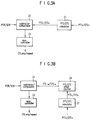
- a conventional system for synchronizing audio and video signals includes a system decoder 1 for parsing a system data packet and outputting compressed data of the audio and video signals and PTS/DTS and PCR or SCR, a voltage-controlled oscillator (VCO) 4 for generating a clock of 27MHz for MPEG2 or 90KHz for MPEG1, and controlling a generated frequency according to the magnitude of a reference voltage Vref, an STC counter 3 for initializing the PCR or SCR output from system decoder 1 at the initial operation of the system, counting it using the output clock of VCO 4, and outputting the STC, a subtractor for comparing the PCR or SCR output from system decoder 1 with the STC output from STC counter 3 and varying the reference voltage of VCO 4 so that an error, that is, the difference between the PCR or SCR and STC is reduced, a clock generator 5 for dividing the clock output from VCO 4 to generate horizontal and vertical sync signals Hsync and Vsyn
- system decoder 1 outputs the compressed data of audio and video signals, DTS, PTS, and PCR or SCR.
- STC counter 3 counts the PCR or SCR by the clock output from VCO 4, and outputs the STC.
- the STC output from STC counter 3 is compared with the PCR or SCR in subtractor 2 so that the magnitude of reference voltage Vref is controlled and thus the output frequency of VCO 4 is controlled to reduce the error, that is, the difference between the compared values.
- the value input to VCO 4 is a value in which the output of subtractor 2 is converted into analog by a D/A converter (not shown).
- clock generator 5 divides it in a predetermined division value, to output horizontal and vertical sync signals Hsync and Vsync and PCM clock PCMclk of audio signal.
- start controller 9 starts the operation of audio/video decoder 6 and audio/video playing portion 8.
- Audio/video decoder 6 decodes the compressed data so that the restored audio/video data is stored in frame memory 7.
- the decoding ready signal indicating that decoding of a video/audio frame is finished is output to audio/video playing portion 8.
- Audio/video playing portion 8 displays the decoded video data in synchronization with horizontal and vertical sync signals Hsync and Vsync output from clock generator 5, and plays the audio frame data in synchronization with audio PCM clock PCMclk.
- Start controller 9 compares the STC from STC counter 3 with the PTS or DTS input from system decoder 1 in order to control the operations of audio/video decoder 6 and audio/video playing portion 8.
- an audio/video synchronizer for a digital TV in which audio/video synchronization control is performed using SCR, PCR or PTS/DTS sent from the transmission side in a digital PTS/DTS controller, requiring no D/A converter and VCO used for clock control in prior art, enabling ASIC, and reducing production cost.
- an audio/video synchronizer for a digital TV comprising: a system decoder for parsing an input data packet and outputting compressed data of audio and video signals and PTS/DTS and PCR or SCR; an audio/video decoder for decoding the compressed data output from the system decoder, outputting a DTS for the video or audio frame to be decoded, and outputting a decoding ready signal indicating that decoding of the video or audio frame is finished, and a PTS of corresponding data; a frame memory for storing the audio/video data from the audio/video decoder; a clock generator for dividing an input clock into a predetermined value to generate horizontal and vertical sync signals and a PCM clock of the audio signal; an audio/video playing portion for playing the data decoded in the audio/video decoder according to the decoding ready signal in synchronization with the vertical and horizontal sync signals from the clock generator and the audio PCM clock, and outputting the PTS of a picture
- an audio/video synchronizer for a digital TV comprising: a system decoder for parsing an input data packet and outputting compressed data of audio and video signals and PTS/DTS and PCR or SCR; an audio/video decoder for decoding the compressed data output from the system decoder, outputting a DTS for the video or audio frame to be decoded, and outputting a decoding ready signal indicating that decoding of the video or audio frame is finished, and a PTS of corresponding data; a frame memory for storing the audio/video data from the audio/video decoder; a clock generator for dividing an input clock according to a division control signal to generate horizontal and vertical sync signals and a PCM clock of the audio signal; an audio/video playing portion for playing the data decoded in the audio/video decoder according to the decoding ready signal in synchronization with the vertical and horizontal sync signals from the clock generator and the audio PCM clock, and outputting the PTS of a
- an audio/video synchronizer for a digital TV comprising: a system decoder for parsing an input data packet and outputting compressed data of audio and video signals and PTS/DTS and PCR or SCR; an STC generator for receiving and counting PCR or SCR from the system decoder to thereby an STC value; an audio/video decoder for decoding the compressed data output from the system decoder, outputting a DTS for the video or audio frame to be decoded, and outputting a decoding ready signal indicating that decoding of the video or audio frame is finished, and a PTS of corresponding data; a frame memory for storing the audio/video data from the audio/video decoder; a clock generator for dividing an input clock according to a division value to generate horizontal and vertical sync signals and a PCM clock of the audio signal; an audio/video playing portion for playing the data decoded in the audio/video decoder according to the decoding ready signal in synchronization with the vertical and
- an audio/video synchronizer for a digital TV comprising: a system decoder for parsing an input data packet and outputting compressed data of audio and video signals and PTS/DTS and PCR or SCR; an STC generator for receiving and counting PCR or SCR from the system decoder to thereby an STC value; an audio/video decoder for decoding the compressed data output from the system decoder, outputting a DTS for the video or audio frame to be decoded, and outputting a decoding ready signal indicating that decoding of the video or audio frame is finished, and a PTS of corresponding data; a frame memory for storing the audio/video data from the audio/video decoder; a clock generator for dividing an input clock according to a division value to generate horizontal and vertical sync signals and a PCM clock of the audio signal; an audio/video playing portion for playing the data decoded in the audio/video decoder according to the decoding ready signal in synchronization with the vertical
- an audio/video synchronizer for a digital TV comprising: a system decoder for parsing an input data packet and outputting compressed data of audio and video signals and PTS/DTS and PCR or SCR; an STC generator for receiving and counting PCR or SCR from the system decoder to thereby an STC value; an audio/video decoder for decoding the compressed data output from the system decoder, outputting a DTS for the video or audio frame to be decoded, and outputting a decoding ready signal indicating that decoding of the video or audio frame is finished, and a PTS of corresponding data; a frame memory for storing the audio/video data from the audio/video decoder; a clock generator for dividing an input clock according to a division value to generate horizontal and vertical sync signals and a PCM clock of the audio signal; an audio/video playing portion for playing the data decoded in the audio/video decoder according to the decoding ready signal in synchronization with the vertical
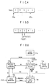
- a first embodiment of the audio/video synchronizer for a digital TV of the present invention comprises a system decoder 11 for parsing a system data packet and outputting compressed data of the audio and video signals and PTS/DTS and PCR or SCR, an audio/video decoder 13 for decoding the compressed data output from system decoder 11, outputting a DTS for the video or audio frame to be decoded, and outputting a decoding ready signal indicating that decoding of the video or audio frame is finished, and a PTS of corresponding data, a frame memory 14 for storing the audio/video data from audio/video decoder 13, a clock generator 15 made with a crystal oscillator for dividing an input clock into a predetermined value to generate horizontal and vertical sync signals Hsync and Vsync and PCM clock PCMclk of audio signal, an audio/video playing portion 16 for displaying the video data decoded in audio/video decoder 13 according to the decoding ready signal of audio/video de
- a first embodiment of PTS/DTS controller 12 comprises a PTS/DTS calculator 21 for receiving the PTS value PTS0 of the first frame to which the PTS is input or the DTS value DTS0 of the first frame to which the DTS is input, and obtaining the PTS value PTS n or DTS value DTS n input to a next frame (nth frame) after PTS0 or DTS0 of the first frame is input, thereby calculating the PTS or DTS value with respect to a picture or frame where the PTS or DTS is absent, a subtractor/comparator 22 for receiving PCR/SCR value from system decoder 11 and PTS n /DTS n from PTS/DTS calculator 21 to compare them, and deciding whether their difference is within or out of a predetermined value, and a sync controller 23 for controlling audio/video decoder 13 and audio/video playing portion 16, according to the output signal of subtractor/comparator 22, to skip or repeat one frame of data.
- a second embodiment of PTS/DTS controller 12 further comprises a PTS/DTS offset counter 24 for receiving PTS n /DTS n value from PTS/DTS calculator 21 and counting the PTS n or DTS n until a new PCR or SCR is input, to thereby output counted value PTS cn /DTS cn .
- a data packet is parsed in system decoder 11 to obtain compressed data, PTS or DTS and PCR or SCR.
- the compressed data and PTS or DTS are output to audio/video decoder 13.
- PCR or SCR is output to PTS/DTS controller 12.
- Audio/video decoder 13 decodes the compressed data and stores it to frame memory 14.
- the DTS for the picture or audio frame to be decoded is transmitted to PTS/DTS controller 12.
- a decoding ready signal indicating that decoding is finished and the PTS value for corresponding data are transmitted to audio/video playing portion 16.
- PTS/DTS controller 12 receives the DTS value from audio/video decoder 13 or PTS value from audio/video playing portion 16, which are compared with the PCR or SCR input from system decoder 11.
- the current state is played continuously.
- the video data is displayed in synchronization with the horizontal and vertical sync signals from clock generator 15.
- the audio data is played according to the audio PCM clock from clock generator 15.
- control audio/video decoder 13 and audio/video playing portion 16 are output to control audio/video decoder 13 and audio/video playing portion 16 to skip or repeat one frame of data.
- Audio/video decoder 13 and audio/video playing portion 16 skip or repeat an audio or video frame according to the control signal of PTS/DTS controller 12 in order to synchronize the video and audio signals.
- the operation of the first embodiment of PTS/DTS controller 12 will be explained below in more detail.
- a system data packet has no PTS or DTS value for every frame. For frames having no PTS or DTS value, they must be calculated in PTS/DTS calculator 21.
- PTS n PTS 0 + Offset int * n
- DTS n DTS 0 + Offset int * n + Offset delay
- Subtractor/comparator 22 receives the PCR or SCR value from system decoder 11 and PTS n /DTS n from PTS/DTS calculator 21, and compares them to decide whether their difference is within reference values Ref1 or Ref2.
- Ref1 ⁇ PCR - PTS n ⁇ Ref2 Ref1 ⁇ SCR - PTS n ⁇ Ref2 Ref1 ⁇ PCR - DTS n ⁇ Ref2 Ref1 ⁇ SCR - DTS n ⁇ Ref2 are performed to the audio or video data.
- reference values Ref1 and Ref2 are the same value with different signs.
- Two reference values Ref1 and Ref2 are used because the decoding side, that is, the reception side, has a faster or slower clock than the encoding side, that is, the transmission side.
- the PCR/SCR value is point A
- the clock of the decoding side is slower than that of the encoding side
- point a may be 3.5. If the clock of the decoding side is faster than that of the encoding side, point a may become 2.5.
- reference value Ref1 is -1 and Ref2 is 1, referring to Fig.
- sync controller 23 continuously plays video and audio data as in the current state, without skip or repeat.
- sync controller 23 repeats the frame played in order to delay time, or skips the prior-to-decoding frame, to thereby perform synchronization.
- an absolute value is taken to PCR - PTS n or SCR - PTS n and PCR - DTS n or SCR - DTS n , only the positive value of reference values Ref1 and Ref2 may be used for comparison.
- PTS/DTC offset counter 24 receives the PTS n /DTS n values from PTS/DTS calculator 21, and counts the PTS n or DTS n value until a new PCR or SCR is input.
- the counted values PTS cn /DTS cn are input to subtractor/comparator 22, to be compared with the PCR or SCR input from system decoder 11.
- Other operations are the same as the first embodiment of the PTS/DTS controller, which will not be described.
- the second embodiment of the PTS/DTS controller ensures more precise sync control than the first embodiment because it compares the SCR or PCR with the value in which PTS n /DTS n is counted.
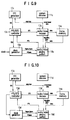
- the second embodiment of the audio/video synchronizer for a digital TV of the present invention varies the division value of clock generator 15a in PTS/DTS controller 12 in order to synchronize the audio and video signals.
- the second embodiment of the audio/video synchronizer for a digital TV comprises a system decoder 11a for parsing a system data packet and outputting compressed data of the audio and video signals and PTS/DTS and PCR or SCR, an audio/video decoder 13a for decoding the compressed data output from system decoder 11a to output restored audio and video data, outputting a DTS for the video or audio frame to be decoded, and outputting a decoding ready signal indicating that decoding of the video or audio frame is finished, and a PTS of corresponding data, a frame memory 14a for storing the audio/video data from audio/video decoder 13a, a clock generator 15a for dividing an input clock into a predetermined value to generate horizontal and vertical sync signals Hsync and Vsync and PCM clock PCMclk of audio signal, an audio/video playing portion 16a for displaying the video data decoded in audio/video decoder 13a according to the decoding ready signal of
- PTS/DTS controller 12a has the same configuration as the first and second embodiments of Figs. 3A and 3B of the first embodiment of the audio/video synchronizer, which will not be explained in detail.
- the operations of system decoder 11a, audio/video decoder 13a, frame memory 14a, and audio/video playing portion 16a are the same as those of the first embodiment, and will not be explained. However, the operations of PTS/DTS controller 12a and clock generator 15a will be described below.
- PTS/DTS controller 12 compares the PTS input from audio/video playing portion 16a or the DTS value input from audio/video decoder 13a with the PCR or SCR value input from the system decoder 11a, and if their difference is within reference values Ref1 and Ref2, plays the current state. If the difference is out of the reference values, division control signal CS1 is output to clock generator 15a in order to control clock division.
- Clock generator 15a divides input clock Clock according to the division control of PTS/DTS controller 12a so that horizontal and vertical sync signals Hsync and Vsync and audio PCM clock PCMclk are varied.
- audio/video playing portion 16a displaying of video signal and playing of audio signal are performed so that the video and audio signals are output in synchronization.
- sync controller 23 of PTS/DTS controller 12a varies the division value of clock generator 15a according to the output of subtractor/comparator 22 in order to synchronize the audio and video signals.
- the frequency of horizontal sync the frequency of input clock ⁇ horizontal divider H
- the frequency of vertical sync the frequency of input clock ⁇ vertical divider V
- the frequency of PCM clock the frequency of input clock ⁇ audio divider A , divider H, divider V and divider A are rendered smaller or greater to vary the horizontal and vertical sync signals and PCM clock and thus synchronize the audio and video signals.
- sync controller 23 the operations of other components except sync controller 23 are the same as the first and second embodiments of the first embodiment of the audio/video synchronizer, and thus will not be explained.
- the third embodiment thereof further comprises an STC generator 17b.
- STC generator 17b receives PCR or SCR value from system decoder 11b, counts the PCR or SCR, and outputs the counted value STC to PTS/DTS controller 12b. If a new PCR or SCR is input, the counted value is initialized to the input value, and then counting is started again.
- PTS/DTS controller 12b is configured in the same way as the first embodiment of the first embodiment of the audio/video synchronizer of the present invention, as shown in Fig. 8.
- PTS/DTS controller 12b compares the STC value input from STC generator 17b with the DTS value input from audio/video decoder 13b or the PTS value input from audio/video playing portion 16b so that according to the result, as in the first embodiment, audio/video decoder 13b and audio/video playing portion 16b skip or repeat one frame of data.
- Subtractor/comparator 22b of PTS/DTS controller 12b compares the STC value input from STC generator 16b with the PTS n or DTS n input from PTS/DTS calculator 21, and if their difference between the STC value and PTS n or DTS n is within reference values Ref1 and Ref2, displays the current state. If the difference is out of reference values Ref1 and Ref2, sync controller 23b repeats the frame displayed for time delay, or skips the prior-to-decoding frame, for the purpose of synchronization.
- Ref1 ⁇ STC - PTS n ⁇ Ref2 or Ref1 ⁇ STC - DTS n ⁇ Ref2 is performed with respect to the audio or video data. If STC - PTS n or STC - DTS n is not within reference values Ref1 and Ref2, sync controller 23b repeats the frame displayed for time delay or skips the prior-to-decoding frame in the same way as the first embodiment. By doing so, synchronization is carried out.
- the fourth embodiment of the audio/video synchronizer for a digital TV of the present invention is constructed in such a manner that STC generator 17c is added to the second embodiment. As shown in Fig. 9, STC generator 17c is made in the same configuration as the third embodiment. PTS/DTS controller 12c of the fourth embodiment is made in the same configuration as PTS/DTS controller 12b of the third embodiment of Fig. 8.
- PTS/DTS controller 12c compares the STC value input from STC generator 17c with the DTS value input from audio/video decoder 13c or the PTS value input from audio/video playing portion 16b, and if their difference is within reference values Ref1 and Ref2, plays the current state. If the difference is out of reference values Ref1 and Ref2, the controller controls the clock division of clock generator 15a.
- Clock generator 15a divides the input clock Clock according to the control of the division value from PTS/DTS controller 12c, and varies horizontal and vertical sync signals Hsync and Vsync and PCM clock PCMclk of the audio signal so that displaying of video signal and playing of audio signal are performed in audio/video playing portion 16a. Through this process, the video and audio signals are synchronized.
- sync controller 23 of PTS/DTS controller 12c varies the division value of clock generator 15a according to the output of subtractor/comparator 22 in order to synchronize the audio and video signals.
- the sync controller operates in the same fashion as that of the second embodiment, which will not be explained.
- the fourth embodiment of the present invention combines the second and third embodiments so that STC generator 17c functioning in the same way as the third embodiment is added. Then, the STC value of PTS/DTS controller 12c and the PTS or DTS are compared so that a division control signal CS2 is output to clock generator 15c as discussed in the second embodiment in order to vary the clock division value of clock generator 15c. By doing so, the synchronization control of audio and video signals is carried out.
- the fifth embodiment of the audio/video synchronizer for a digital TV of the present invention is constructed in the same way as the third and fourth embodiments, as shown in Fig. 10.
- PTS/DTS controller 12d compares the STC value of STC generator 17d with the DTS value of audio/video decoder 13d or the PTS value of audio/video playing portion 16d, and thus varies the input clock Clock of clock generator 15d. This varies the output of horizontal and vertical sync signals Hsync and Vsync and PCM clock PCMclk according to the fixed division value of clock generator 15d, performing the synchronization control of audio and video signals.
- PTS/DTS controller 12d of the fifth embodiment of the present invention comprises a first adder 31 for outputting an error signal for correcting the clock frequency of the reception side, that is, the difference between the DTS value of a picture or frame decoded from audio/video decoder 13d or the PTS value of the picture or frame played from audio/video playing portion 16d and the STC value input from STC generator 17d, a loop filter 32 for removing the jitter form the output of first adder 31, and a numerically controlled oscillator (NCO) 33 for receiving the output of loop filter 32 and tracing the clock of the encoding side.
- NCO numerically controlled oscillator
- loop filter 32 comprises a second adder 41 for adding the data output from first adder 31 to the previous data, a first register 42 for temporarily storing and outputting the output of second adder 41 and simultaneously feeding it back to one input port of second adder 41, a third adder 43 for adding the output of first register 42 to the previous output, and a second register 44 for temporarily storing the output of the third adder and feeding it back to one input port of third adder 43.
- the first embodiment of NCO 33 comprises a fourth adder 51 for adding the data output from loop filter 32 to the previous output data, and a third register 52 for temporarily storing the output of fourth adder 51 to output its MSB and simultaneously feed it back to one input port of fourth adder 51.
- the second embodiment of NCO 33 comprises a fifth adder 61 for adding the data output from loop filter 32 to the previous output data, a fourth register 62 for temporarily storing and outputting the output of fifth adder 61 and simultaneously feeding it back to one input port of fifth adder 61, a counter 63 for repeating counting as many as the number of set bits and outputting the result, an EXCLUSIVE-OR gate 64 for EXCLUSIVE-OR-operating the output of fourth register 62 and the output of counter 63, and a T flipflop 65 for toggling and outputting the output of EXCLUSIVE-OR gate 64.
- the PTS/DTS is transmitted once at least in 0.1 second.
- first adder 31 obtains error information of N1 bit from the received PTS (K) /DTS( K ) and STC value, that is, the difference between PTS (K) /DTS( K ) and STC value.
- the error information output of N1 bit of first adder 31 is continuously accumulated through second adder 41 and first register 42 of loop filter 32, thereby obtaining error component ⁇ (K) of N3 bit from which jitter is removed.
- the number of the output bit N2 of first register 42 and the number of the input bit N3 of third adder 43 are not the same.
- Third adder 43 and second register 44 form a new error value ⁇ (K) from error component ⁇ (K) and frequency error value ⁇ (K-1) of the previous state.
- new error value ⁇ (K-1) is calculated at a point where PTS (K) /DTS( K ) is received.
- the value of third register 52 of N6 bit determined by the clock frequency of the system is added to the output ⁇ (K) of loop filter 32 in fourth adder 51 in order to output the MSB.
- fourth adder 51 operates at the system clock frequency so that fifth adder 61 operates only when the PTS/DTS is received.
- fourth register 62 is updated by EXCLUSIVE-OR gate 64 if the value of counter 63 and the value of fourth register 62 are the same.
- T flipflop 65 a clock is generated.
- fourth register 62 is updated by EXCLUSIVE-OR gate 64 if the value of counter 63 and the value of fourth register 62 are the same so that fifth adder 61 may be slower than fourth adder 51 in performance speed.
- PTS/DTS controllers 12 and 12b operate in the current state. If the difference is out of the reference value, one frame of audio or video data is skipped or repeated in controlling their synchronization.
- PTS/DTS controllers 12a and 12c operate in the current state. If the difference is out of the reference value, the division value of clock generators 15a and 15c is varied to control the speed of the horizontal and vertical sync signals and the audio PCM clock. By doing so, the synchronization of the audio and video signals is controlled.
- PTS/DTS controllers 12d operate in the current state. If the difference is out of the reference value, the input clock of clock generators 15d is varied to control the speed of the horizontal and vertical sync signals and the audio PCM clock. By doing so, the synchronization of the audio and video signals is controlled.
- the present invention requires no VCO and D/A converter, reducing its production cost.
- the present invention is made in a digital form so that it may become ASIC using a super-density technology.
- the present invention can vary a separate clock in synchronizing audio and video signals so that it can be employed to all the audio/video signal processing systems made in the MPEG standard.
Landscapes
- Engineering & Computer Science (AREA)
- Multimedia (AREA)
- Signal Processing (AREA)
- Compression Or Coding Systems Of Tv Signals (AREA)
- Two-Way Televisions, Distribution Of Moving Picture Or The Like (AREA)
Applications Claiming Priority (4)
| Application Number | Priority Date | Filing Date | Title |
|---|---|---|---|
| KR1019940033332A KR100311464B1 (ko) | 1994-12-08 | 1994-12-08 | 디지탈티브이의오디오/비디오동기장치 |
| KR3333294 | 1994-12-08 | ||
| KR1019950020847A KR100348240B1 (ko) | 1995-07-14 | 1995-07-14 | 엔씨오를이용한피티에스/디티에스콘트롤러 |
| KR2084795 | 1995-07-14 |
Publications (3)
| Publication Number | Publication Date |
|---|---|
| EP0716547A2 true EP0716547A2 (fr) | 1996-06-12 |
| EP0716547A3 EP0716547A3 (fr) | 1998-05-06 |
| EP0716547B1 EP0716547B1 (fr) | 2002-03-20 |
Family
ID=26630752
Family Applications (1)
| Application Number | Title | Priority Date | Filing Date |
|---|---|---|---|
| EP95308933A Expired - Lifetime EP0716547B1 (fr) | 1994-12-08 | 1995-12-08 | Synchronisateur audio/vidéo |
Country Status (3)
| Country | Link |
|---|---|
| US (1) | US5771075A (fr) |
| EP (1) | EP0716547B1 (fr) |
| DE (1) | DE69525908T2 (fr) |
Cited By (5)
| Publication number | Priority date | Publication date | Assignee | Title |
|---|---|---|---|---|
| EP0896479A2 (fr) * | 1997-08-08 | 1999-02-10 | Samsung Electronics Co., Ltd. | Circuit et méthode de synchronisation pour un décodeur de données vidéo |
| EP0880246A3 (fr) * | 1997-05-15 | 1999-12-01 | Matsushita Electric Industrial Co., Ltd. | Décodeur de signaux codés comprimés et décodeur de signaux radio |
| EP1193981A2 (fr) * | 1997-09-05 | 2002-04-03 | Matsushita Electric Industrial Co., Ltd. | Procédé de décodage et support d'enregistrement où est enregistré un programme de décodage |
| DE19860507B4 (de) * | 1997-12-29 | 2012-01-19 | Lg Electronics Inc. | Videocodierverfahren, Videodecoder und digitales Fernsehsystem unter Verwendung eines solchen Verfahrens und eines solchen Decoders |
| CN101848396B (zh) * | 2009-11-30 | 2012-10-17 | 深圳市华曦达科技股份有限公司 | 传输流音视频同步及防抖动方法 |
Families Citing this family (42)
| Publication number | Priority date | Publication date | Assignee | Title |
|---|---|---|---|---|
| JP3130464B2 (ja) * | 1996-02-02 | 2001-01-31 | ローム株式会社 | データ復号装置 |
| KR100200617B1 (ko) * | 1996-09-05 | 1999-06-15 | 윤종용 | 픽쳐 동기화회로 및 그 방법 |
| JP2970558B2 (ja) * | 1996-10-25 | 1999-11-02 | 日本電気株式会社 | オーディオ/ビデオ/コンピュータグラフィクス同期再生合成方式及び方法 |
| US6192074B1 (en) * | 1997-05-14 | 2001-02-20 | Sarnoff Corporation | Fixed frequency source timing processor method and apparatus |
| GB2326781B (en) * | 1997-05-30 | 2001-10-10 | British Broadcasting Corp | Video and audio signal processing |
| KR100234265B1 (ko) * | 1997-06-17 | 1999-12-15 | 윤종용 | 캡션 데이터 처리 회로 및 그 방법 |
| US6191822B1 (en) * | 1997-06-20 | 2001-02-20 | Sony Corporation | Method of and apparatus for separating audio and video data from a combined audio/video stream of data |
| US5959684A (en) * | 1997-07-28 | 1999-09-28 | Sony Corporation | Method and apparatus for audio-video synchronizing |
| US6195403B1 (en) * | 1997-09-26 | 2001-02-27 | International Business Machines Corporation | Pulse generator for a voltage controlled oscillator |
| JP3418966B2 (ja) * | 1997-10-09 | 2003-06-23 | インターナショナル・ビジネス・マシーンズ・コーポレーション | 同期化方法及びデコーダ |
| US6081299A (en) * | 1998-02-20 | 2000-06-27 | International Business Machines Corporation | Methods and systems for encoding real time multimedia data |
| US6429902B1 (en) * | 1999-12-07 | 2002-08-06 | Lsi Logic Corporation | Method and apparatus for audio and video end-to-end synchronization |
| US6502097B1 (en) * | 1999-12-23 | 2002-12-31 | Microsoft Corporation | Data structure for efficient access to variable-size data objects |
| JP4208398B2 (ja) * | 2000-10-05 | 2009-01-14 | 株式会社東芝 | 動画像復号再生装置、動画像復号再生方法及びマルチメディア情報受信装置 |
| US6636270B2 (en) * | 2000-12-14 | 2003-10-21 | Microsoft Corporation | Clock slaving methods and arrangements |
| TW499818B (en) * | 2001-03-29 | 2002-08-21 | Winbond Electronics Corp | Audio/video packet synchronous decoding method |
| US7012650B2 (en) * | 2001-06-14 | 2006-03-14 | Sony Corporation | Start/stop audio encoder apparatus and method for synchronizing digital audio and video signals |
| US7120168B2 (en) * | 2001-11-20 | 2006-10-10 | Sony Corporation | System and method for effectively performing an audio/video synchronization procedure |
| US9497452B2 (en) * | 2002-01-22 | 2016-11-15 | Broadcom Corporation | System and method of transmission and reception of video using compressed differential time stamps |
| US7729421B2 (en) * | 2002-02-20 | 2010-06-01 | International Business Machines Corporation | Low latency video decoder with high-quality, variable scaling and minimal frame buffer memory |
| US9948977B2 (en) * | 2003-01-09 | 2018-04-17 | Avago Technologies General Ip (Singapore) Pte. Ltd. | System, method, and apparatus for determining presentation time for picture without presentation time stamp |
| AU2003286797A1 (en) * | 2002-11-07 | 2004-06-03 | Thomson Licensing S.A. | A system and method for determining lip synchronization between audio and video in a digitized environment using buffer calculation |
| CN100536555C (zh) * | 2003-03-19 | 2009-09-02 | 松下电器产业株式会社 | 数据处理装置 |
| KR100619007B1 (ko) * | 2003-06-24 | 2006-08-31 | 삼성전자주식회사 | 비디오 트랜스포트 스트림 동기화 제어 장치 및 방법 |
| EP1814327B1 (fr) * | 2003-07-03 | 2008-05-21 | Matsushita Electric Industrial Co., Ltd. | Support d'enregistrement, appareil de lecture, procédé d'enregistrement, circuit intégré, programme, et procédé de lecture |
| US9137502B2 (en) | 2004-08-25 | 2015-09-15 | Broadcom Corporation | Method and system for fast digital channel change utilizing time-stamp management |
| US7480315B2 (en) * | 2004-12-31 | 2009-01-20 | Microsoft Corporation | Method and apparatus for synchronizing clocks |
| KR101246916B1 (ko) | 2006-04-21 | 2013-03-25 | 삼성전자주식회사 | 오디오/비디오 동기 보정 방법 및 장치 |
| KR101143907B1 (ko) * | 2007-02-15 | 2012-05-10 | 삼성전자주식회사 | 디지털 방송 재생 방법 및 장치 |
| KR101226178B1 (ko) * | 2007-03-27 | 2013-01-24 | 삼성전자주식회사 | 비디오 데이터 디스플레이 방법 및 장치 |
| US7724684B2 (en) * | 2007-05-24 | 2010-05-25 | Modelware, Inc. | System and method for designing and implementing packet processing products |
| CN101340591B (zh) * | 2008-08-11 | 2011-04-06 | 华为终端有限公司 | 解码系统中接收视音频数据的处理方法及装置 |
| CN101616331B (zh) * | 2009-07-27 | 2011-07-20 | 北京汉邦高科数字技术有限公司 | 一种对视频帧率及音视频同步性能进行测试的方法 |
| CN101916577B (zh) * | 2010-08-19 | 2016-09-28 | 无锡中感微电子股份有限公司 | 一种音视频播放同步的方法及装置 |
| EP2490446A1 (fr) | 2011-02-15 | 2012-08-22 | Eldon Technology Limited | Protection contre la copie |
| CN103621102B (zh) | 2011-05-12 | 2017-05-03 | 英特尔公司 | 用于音频与视频同步的方法、装置及系统 |
| US9191686B2 (en) | 2011-07-22 | 2015-11-17 | Honeywell International Inc. | System and method of implementing synchronized audio and video streaming |
| US9154832B2 (en) | 2012-03-29 | 2015-10-06 | Dish Network L.L.C. | Testing frame color counting technique |
| US8570379B1 (en) * | 2012-10-04 | 2013-10-29 | Dish Network L.L.C. | Frame block comparison |
| KR20170068946A (ko) * | 2015-12-10 | 2017-06-20 | 삼성전자주식회사 | 방송 수신 장치 및 방송 수신 장치의 제어 방법 |
| US20170223382A1 (en) * | 2016-02-03 | 2017-08-03 | Sigma Designs, Inc. | Method of reducing latency and a video decoder of the same |
| CN111954064B (zh) * | 2020-08-31 | 2022-11-04 | 三星电子(中国)研发中心 | 音视频同步方法和装置 |
Citations (5)
| Publication number | Priority date | Publication date | Assignee | Title |
|---|---|---|---|---|
| DE4335271A1 (de) * | 1992-10-16 | 1994-05-05 | Sony Corp | Daten-Demultiplexer |
| EP0618728A2 (fr) * | 1993-02-26 | 1994-10-05 | Sony Corporation | Synchronisation d'information audio/vidéo |
| EP0626770A2 (fr) * | 1993-05-25 | 1994-11-30 | Sony Corporation | Multiplexeurs et démultiplexeurs de données |
| EP0648056A2 (fr) * | 1993-09-30 | 1995-04-12 | Thomson Consumer Electronics, Inc. | Synchronisation audio/vidéo dans un système de transmission numérique |
| EP0649259A2 (fr) * | 1993-10-15 | 1995-04-19 | Sony Corporation | Dispositif de reproduction de données |
Family Cites Families (6)
| Publication number | Priority date | Publication date | Assignee | Title |
|---|---|---|---|---|
| US5287182A (en) * | 1992-07-02 | 1994-02-15 | At&T Bell Laboratories | Timing recovery for variable bit-rate video on asynchronous transfer mode (ATM) networks |
| US5598352A (en) * | 1994-09-30 | 1997-01-28 | Cirrus Logic, Inc. | Method and apparatus for audio and video synchronizing in MPEG playback systems |
| US5566089A (en) * | 1994-10-26 | 1996-10-15 | General Instrument Corporation Of Delaware | Syntax parser for a video decompression processor |
| KR0137701B1 (ko) * | 1994-12-13 | 1998-05-15 | 양승택 | 엠피이지-2(mpeg-2) 시스템의 피이에스(pes) 패킷화 장치 |
| US5588029A (en) * | 1995-01-20 | 1996-12-24 | Lsi Logic Corporation | MPEG audio synchronization system using subframe skip and repeat |
| US5598415A (en) * | 1995-08-04 | 1997-01-28 | General Instrument Corporation Of Delaware | Transmission of high rate isochronous data in MPEG-2 data streams |
-
1995
- 1995-12-05 US US08/567,689 patent/US5771075A/en not_active Expired - Fee Related
- 1995-12-08 EP EP95308933A patent/EP0716547B1/fr not_active Expired - Lifetime
- 1995-12-08 DE DE69525908T patent/DE69525908T2/de not_active Expired - Lifetime
Patent Citations (5)
| Publication number | Priority date | Publication date | Assignee | Title |
|---|---|---|---|---|
| DE4335271A1 (de) * | 1992-10-16 | 1994-05-05 | Sony Corp | Daten-Demultiplexer |
| EP0618728A2 (fr) * | 1993-02-26 | 1994-10-05 | Sony Corporation | Synchronisation d'information audio/vidéo |
| EP0626770A2 (fr) * | 1993-05-25 | 1994-11-30 | Sony Corporation | Multiplexeurs et démultiplexeurs de données |
| EP0648056A2 (fr) * | 1993-09-30 | 1995-04-12 | Thomson Consumer Electronics, Inc. | Synchronisation audio/vidéo dans un système de transmission numérique |
| EP0649259A2 (fr) * | 1993-10-15 | 1995-04-19 | Sony Corporation | Dispositif de reproduction de données |
Cited By (9)
| Publication number | Priority date | Publication date | Assignee | Title |
|---|---|---|---|---|
| EP0880246A3 (fr) * | 1997-05-15 | 1999-12-01 | Matsushita Electric Industrial Co., Ltd. | Décodeur de signaux codés comprimés et décodeur de signaux radio |
| US6118821A (en) * | 1997-05-15 | 2000-09-12 | Matsushita Electric Industrial Co., Ltd. | Compressed code decoding device and audio decoding device |
| US7069223B1 (en) | 1997-05-15 | 2006-06-27 | Matsushita Electric Industrial Co., Ltd. | Compressed code decoding device and audio decoding device |
| EP0896479A2 (fr) * | 1997-08-08 | 1999-02-10 | Samsung Electronics Co., Ltd. | Circuit et méthode de synchronisation pour un décodeur de données vidéo |
| EP0896479A3 (fr) * | 1997-08-08 | 2004-10-20 | Samsung Electronics Co., Ltd. | Circuit et méthode de synchronisation pour un décodeur de données vidéo |
| EP1193981A2 (fr) * | 1997-09-05 | 2002-04-03 | Matsushita Electric Industrial Co., Ltd. | Procédé de décodage et support d'enregistrement où est enregistré un programme de décodage |
| EP1193981A3 (fr) * | 1997-09-05 | 2002-05-15 | Matsushita Electric Industrial Co., Ltd. | Procédé de décodage et support d'enregistrement où est enregistré un programme de décodage |
| DE19860507B4 (de) * | 1997-12-29 | 2012-01-19 | Lg Electronics Inc. | Videocodierverfahren, Videodecoder und digitales Fernsehsystem unter Verwendung eines solchen Verfahrens und eines solchen Decoders |
| CN101848396B (zh) * | 2009-11-30 | 2012-10-17 | 深圳市华曦达科技股份有限公司 | 传输流音视频同步及防抖动方法 |
Also Published As
| Publication number | Publication date |
|---|---|
| EP0716547B1 (fr) | 2002-03-20 |
| DE69525908D1 (de) | 2002-04-25 |
| US5771075A (en) | 1998-06-23 |
| DE69525908T2 (de) | 2002-07-25 |
| EP0716547A3 (fr) | 1998-05-06 |
Similar Documents
| Publication | Publication Date | Title |
|---|---|---|
| EP0716547B1 (fr) | Synchronisateur audio/vidéo | |
| RU2142210C1 (ru) | Устройство для получения синхронизированных воспроизведенных сигналов звука и изображения | |
| US6018376A (en) | Synchronous reproduction apparatus | |
| EP0731615B1 (fr) | Système de décodage vidéo pour décoder des données vidéo en synchronisation avec une horloge de système | |
| US20160366431A1 (en) | Video decoding device and video decoding method | |
| JPH10511238A (ja) | 再生システムのための同期方法及び装置 | |
| JPH10511513A (ja) | Mpeg再生システムにおいてオーディオとビデオを同期するための方法及び装置 | |
| US20060120462A1 (en) | Compressed stream decoding apparatus and method | |
| JP4643276B2 (ja) | 無線受信装置 | |
| US20040264577A1 (en) | Apparatus and method for controlling the synchronization of a video transport stream | |
| CN101419827B (zh) | 在音频视频交叉文件中进行音频与视频数据同步的方法 | |
| US20010004366A1 (en) | Communication apparatus, communication method and storage medium | |
| JPH11215082A (ja) | ディジタル信号多重化装置及び方法、ディジタル信号伝送装置及び方法、ディジタル信号記録装置及び方法、並びに、記録媒体 | |
| US6356212B1 (en) | Single clock reference for compressed domain processing systems | |
| US20100166080A1 (en) | Video display apparatus | |
| KR100835035B1 (ko) | 신호 처리장치 및 방법 | |
| US20060056507A1 (en) | Method and system for improving video/audio data display fluency | |
| KR100311464B1 (ko) | 디지탈티브이의오디오/비디오동기장치 | |
| US7903774B2 (en) | Method for creating a system clock in a receiver device and corresponding receiver device | |
| JP4026556B2 (ja) | データ伝送装置 | |
| KR100348240B1 (ko) | 엔씨오를이용한피티에스/디티에스콘트롤러 | |
| US5724476A (en) | Method and apparatus for extending and reproducing compressed moving pictures | |
| JPH09247666A (ja) | 動画像復号タイミング推定方法および動画像符号化装置および動画像復号化装置 | |
| US6192074B1 (en) | Fixed frequency source timing processor method and apparatus | |
| JP2001197048A (ja) | マルチストリーム再生装置 |
Legal Events
| Date | Code | Title | Description |
|---|---|---|---|
| PUAI | Public reference made under article 153(3) epc to a published international application that has entered the european phase |
Free format text: ORIGINAL CODE: 0009012 |
|
| 17P | Request for examination filed |
Effective date: 19951220 |
|
| AK | Designated contracting states |
Kind code of ref document: A2 Designated state(s): DE FR GB NL |
|
| PUAL | Search report despatched |
Free format text: ORIGINAL CODE: 0009013 |
|
| AK | Designated contracting states |
Kind code of ref document: A3 Designated state(s): DE FR GB NL |
|
| 17Q | First examination report despatched |
Effective date: 20001031 |
|
| GRAG | Despatch of communication of intention to grant |
Free format text: ORIGINAL CODE: EPIDOS AGRA |
|
| GRAG | Despatch of communication of intention to grant |
Free format text: ORIGINAL CODE: EPIDOS AGRA |
|
| GRAH | Despatch of communication of intention to grant a patent |
Free format text: ORIGINAL CODE: EPIDOS IGRA |
|
| GRAH | Despatch of communication of intention to grant a patent |
Free format text: ORIGINAL CODE: EPIDOS IGRA |
|
| REG | Reference to a national code |
Ref country code: GB Ref legal event code: IF02 |
|
| GRAA | (expected) grant |
Free format text: ORIGINAL CODE: 0009210 |
|
| RAP1 | Party data changed (applicant data changed or rights of an application transferred) |
Owner name: LG ELECTRONICS INC. |
|
| AK | Designated contracting states |
Kind code of ref document: B1 Designated state(s): DE FR GB NL |
|
| REF | Corresponds to: |
Ref document number: 69525908 Country of ref document: DE Date of ref document: 20020425 |
|
| ET | Fr: translation filed | ||
| PLBE | No opposition filed within time limit |
Free format text: ORIGINAL CODE: 0009261 |
|
| STAA | Information on the status of an ep patent application or granted ep patent |
Free format text: STATUS: NO OPPOSITION FILED WITHIN TIME LIMIT |
|
| 26N | No opposition filed |
Effective date: 20021223 |
|
| PG25 | Lapsed in a contracting state [announced via postgrant information from national office to epo] |
Ref country code: NL Free format text: LAPSE BECAUSE OF NON-PAYMENT OF DUE FEES Effective date: 20030701 |
|
| NLV4 | Nl: lapsed or anulled due to non-payment of the annual fee |
Effective date: 20030701 |
|
| PG25 | Lapsed in a contracting state [announced via postgrant information from national office to epo] |
Ref country code: FR Free format text: LAPSE BECAUSE OF NON-PAYMENT OF DUE FEES Effective date: 20030901 |
|
| REG | Reference to a national code |
Ref country code: FR Ref legal event code: ST |
|
| PGFP | Annual fee paid to national office [announced via postgrant information from national office to epo] |
Ref country code: GB Payment date: 20071205 Year of fee payment: 13 |
|
| REG | Reference to a national code |
Ref country code: GB Ref legal event code: S29 |
|
| PGFP | Annual fee paid to national office [announced via postgrant information from national office to epo] |
Ref country code: DE Payment date: 20071206 Year of fee payment: 13 |
|
| PG25 | Lapsed in a contracting state [announced via postgrant information from national office to epo] |
Ref country code: DE Free format text: LAPSE BECAUSE OF THE APPLICANT RENOUNCES Effective date: 20080409 |
|
| REG | Reference to a national code |
Ref country code: GB Ref legal event code: S29 |
|
| PG25 | Lapsed in a contracting state [announced via postgrant information from national office to epo] |
Ref country code: GB Free format text: LAPSE BECAUSE OF THE APPLICANT RENOUNCES Effective date: 20080813 |