EP0715400B1 - Dispositif de régulation désensibilisée de la tension statorique d'un alternateur - Google Patents
Dispositif de régulation désensibilisée de la tension statorique d'un alternateur Download PDFInfo
- Publication number
- EP0715400B1 EP0715400B1 EP95402685A EP95402685A EP0715400B1 EP 0715400 B1 EP0715400 B1 EP 0715400B1 EP 95402685 A EP95402685 A EP 95402685A EP 95402685 A EP95402685 A EP 95402685A EP 0715400 B1 EP0715400 B1 EP 0715400B1
- Authority
- EP
- European Patent Office
- Prior art keywords
- alternator
- gains
- state
- model
- stator voltage
- Prior art date
- Legal status (The legal status is an assumption and is not a legal conclusion. Google has not performed a legal analysis and makes no representation as to the accuracy of the status listed.)
- Expired - Lifetime
Links
Images


Classifications
-
- H—ELECTRICITY
- H02—GENERATION; CONVERSION OR DISTRIBUTION OF ELECTRIC POWER
- H02P—CONTROL OR REGULATION OF ELECTRIC MOTORS, ELECTRIC GENERATORS OR DYNAMO-ELECTRIC CONVERTERS; CONTROLLING TRANSFORMERS, REACTORS OR CHOKE COILS
- H02P9/00—Arrangements for controlling electric generators for the purpose of obtaining a desired output
- H02P9/10—Control effected upon generator excitation circuit to reduce harmful effects of overloads or transients, e.g. sudden application of load, sudden removal of load, sudden change of load
- H02P9/105—Control effected upon generator excitation circuit to reduce harmful effects of overloads or transients, e.g. sudden application of load, sudden removal of load, sudden change of load for increasing the stability
Definitions
- the present invention relates to a device for regulation of the stator voltage of an alternator coupled to an electrical network, this resulting device of a linear approximation of the alternator coupled to electrical network around an operating point nominal defined by several operating parameters of the alternator and comprising several loops of feedback associated with respective acting gains on several state variables measured at the output of the alternator as well as on the integral of an error of setpoint defined by the difference between the voltage stator and a setpoint, to define from the setpoint, a control variable of the alternator applied to the input of it for keep the value of the stator voltage close to the setpoint.
- the invention applies in particular to turbo-generator sets coupled to an electrical network and equipped with an independent cruise control.
- the objective is to act on the tension excitation of the alternator to ensure, whatever either the operating point in which the machine, alternator stability, also called system in the following description, maintaining the stator voltage at a value close to the voltage of setpoint, and finally satisfactory performance in the case of short-circuit setpoint voltage step, load transfer or frequency variation of the network.
- the object of the present invention is therefore to provide a voltage regulation device allowing meet the stability requirements whatever the point of operation of the system, and which moreover is robust against parametric uncertainties due to the modeling and modifications of the topology of the electrical network.
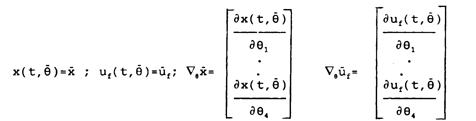
- the subject of the present invention is a device for regulating the stator voltage of a alternator coupled to an electrical network, this device resulting from a linear approximation of the alternator coupled to the electrical network around an operating point nominal defined by several operating parameters of the alternator and having several loops of feedback associated with respective gains acting on several state variables measured at output of the alternator as well as on the integral of an error of setpoint defined by the difference between the stator voltage and a setpoint, to define from the set value, an alternator control variable applied to the entrance of it to maintain the value of the stator voltage close to the value of setpoint, characterized in that the gains of the device are obtained by minimizing the mathematical expectation of a quadratic criterion which is a function of a vector state grouping the derivatives with respect to the time of alternator status variables and setpoint error and the derivative with respect to time of the variable of command, these variables being the state and the input of a linear model, called the augmented system, whose state matrix and input matrix depend on several of the alternator
- the alternator is modeled or approximated according to the known model of the alternator connected to an infinite network.
- the parameters of this system are entirely determined from the operating point defined by the active power P, the reactive power Q, the stator voltage V s and the length of the line X.
- the model defined above makes it possible to determine gains noted K ⁇ , K V , K P , and K I of the regulation device, used in feedback loops in combination with state variables measured at the output of the alternator in order to define from a setpoint V C a variable u for controlling the alternator, as shown in FIG. 2 and will be described in more detail in the following description.
- This method consists in minimizing in space of Hardy a norm noted H-infinity, of the difference between the transfer matrix of the complete linear model and that of the model.
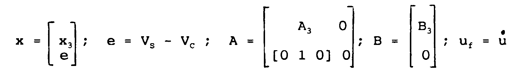
- variable u f is the derivative with respect to time of the control variable u applied by the regulating device to the control input of the alternator.
- the vector x is a state vector of the system and it groups together the state variables measured at the output of the alternator, as well as the reference error e. This state vector x is then said to be increased.
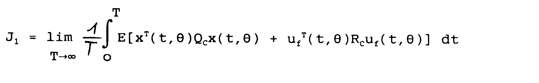
- the gains K ⁇ , K V , K P and K I are determined to minimize the mathematical expectation of the energy associated with the increased state vector x and with the variable u f for uncertain values of the parameters. of the system, close to their nominal value.
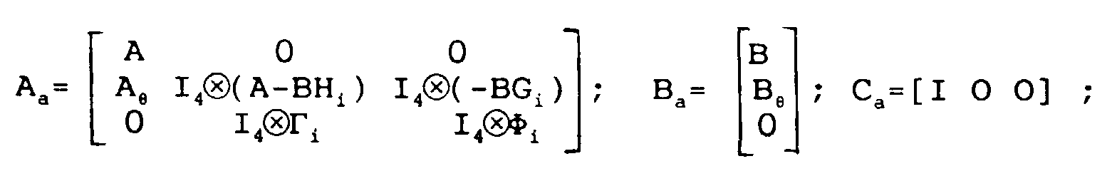
- the minimization of the criterion J 3i provides the gains K i + 1 of the next step i + 1.
- the determination of the initial gains K 0 is obtained in a simple manner. Indeed, as we saw previously, the state variables ⁇ , V S , P of the system are entirely measurable, the gains K 0 are thus obtained by return of state on the linear model (3).
- the control law is such that the variable u f is expressed linearly as a function of the coefficients of the vector x. Consequently, in the modelization (4) associated with this regulator, the terms ⁇ , ⁇ and G are null.
- the state X a of the augmented system (5) consists only of x and ⁇ .
- the corresponding quadratic criterion to minimize J 30 relates to these two quantities and to the variable u f .
- the iterative procedure for obtaining the gains K i is represented in FIG. 1. From the nominal system corresponding to the augmented linear model (3) established in step 10, it is determined in step 12, as just be explained, the initial gains noted K 0 by application of a quadratic linear command on the augmented linear model (3) and minimization of the associated quadratic criterion.
- a state representation is determined in step 14 (4) of the regulation device associated with the gains K i assumed to be known, then an augmented model is determined in step 16 (5 ), from which we conventionally minimize using the theory of the Gaussian quadratic linear command a quadratic criterion J 3i , which makes it possible to obtain the gains K i + 1 .
- the order of the state representation associated with the regulating device of parameters K i + 1 is reduced at each iteration in step 18 by the balanced embodiment method described above.
- a convergence criterion determines in step 20, whether or not it is necessary to further refine the determination of the gains K i + 1 . If this is the case, a new iteration of the iterative procedure is implemented in step 22.
- FIG 2 there is shown a block diagram of the regulation of an alternator by a regulating device according to the invention, thus we find an alternator 50 associated with an excitation device 50A.
- the state variables ⁇ , V S , P At the output of the alternator 50 are measured by conventional adapted sensors (not shown) the state variables ⁇ , V S , P.
- Each of these measured values corresponds to a feedback loop denoted respectively 52, 54 and 56 each provided with an amplifier 58, 60 and 62, the gain of which corresponds to the gains K ⁇ , K V , K P corresponding respectively to each of the state variables ⁇ , V s , P.
- the mechanical power P m is considered to be a disturbing input which is not taken into account for the design of the regulation device.
- the power P in the regulation device shown in FIG. 2 is reduced at 64 by the mechanical power P m measured on the alternator drive turbine.
- the regulator is designed by neglecting the excitation device 50A which, in reality, is inserted between the regulator output and the input of the alternator 50.
- a 50B exciter compensation device is arranged if necessary between the regulator output and the input of the excitation device 50A.
- An additional feedback loop 66 routes the value of the stator voltage V s to a subtraction device 68 calculating the difference between this value and the set value V c .
- the result of this difference is then injected into an integrator 70 before being multiplied by an amplifier 72 whose gain corresponds to the gain K I calculated as explained above.
- the control variable u is then formed from the outputs of the various amplifiers by means of summing and subtracting devices 74 to 80 according to a conventional arrangement making it possible to implement the control law defined above and resulting from the integration of the expression of u f .
- the variable u is then sent to the alternator 50 through the exciter 50B and excitation 50A compensation devices.
- a digital computer is preferably used, for example a computer programmed to generate the control variable u as a function of the state variables ⁇ , V s , P measured at the output of the alternator 50 and of the setpoint V c .
- the stator voltage V S and the line length X are those which influence the most about system stability. In fact, it is difficult to stabilize an alternator connected to a network when the line length X is large or even when the stator voltage V S is low. On the other hand, variations in active power P and reactive power Q have a less significant influence on stability. These different considerations make it possible to design a desensitized regulation device only with respect to the line length X and the stator voltage V S. Thus, for calculations, the vector ⁇ is reduced to two components.
- the matrix Q C being positive semi-defined, it is often chosen diagonal, these diagonal coefficients being noted q ii for i ⁇ ⁇ 1,2,3,4 ⁇ .
- the variable to be regulated is the stator voltage V S. It is therefore necessary to limit the variations of this quantity and make it close to its set value V C as quickly as possible.
- the significant weighting of the stator voltage V S through the coefficient q 22 induces a large gain on the voltage, which limits these variations.
- the weighting coefficient q 44 on the integral of the error e between the set value V C and the stator voltage V S influences the speed with which the set value V C is caught up.
- the larger the value q 44 the faster the stator voltage V s meets the setpoint value V c .
- the electrical power P and the speed ⁇ have a stabilizing role.
- the gains on the speed ⁇ and the active power P are too large, a variation in the frequency of the network, which has a great influence on these two quantities, then has repercussions on the stator voltage V S to be regulated.
- One way of limiting the influence of this disturbance on the stator voltage V S is therefore to reduce the gains on the speed ⁇ and the electric power P.
- the weighting coefficients q 11 and q 33 are taken zero.
Landscapes
- Engineering & Computer Science (AREA)
- Power Engineering (AREA)
- Control Of Eletrric Generators (AREA)
Description
- ledit critère quadratique est fonction des dérivées partielles du vecteur d'état et de la dérivée par rapport au temps de la variable de commande par rapport aux paramètres de l'alternateur et la désensibilisation de l'alternateur régulé est réalisée par minimisation dudit critère quadratique ;
- le modèle linéaire duquel résultent les variables d'état utilisées dans le vecteur d'état est un modèle réduit à un ordre inférieur d'un modèle linéaire complet par une méthode de réalisation équilibrée consistant à minimiser une norme de la différence entre la matrice de transfert du modèle complet et celle du modèle réduit ;
- les gains sont déterminés par une méthode itérative consistant à réaliser à chaque étape une synthèse des gains par une méthode de commande linéaire quadratique gaussienne, consistant à minimiser un critère quadratique, appliquée à un modèle augmenté fonction d'une représentation d'état du dispositif de régulation obtenu avec les gains calculés à l'étape précédente et de la modélisation linéaire du système augmenté ;
- chaque étape de synthèse des gains est suivie par une réduction à un ordre inférieur de la représentation d'état associée à ces gains par une méthode de réalisation équilibrée ;
- les variables d'état sont la vitesse angulaire, la tension statorique et la puissance électrique.
- la figure 1 est un organigramme d'une procédure itérative mise en oeuvre pour la détermination des gains du dispositif de régulation, et
- la figure 2 est un schéma synoptique d'un alternateur régulé utilisant un dispositif de régulation selon l'invention.


Claims (6)
- Dispositif de régulation de la tension statorique (variable à régler Vs) d'un alternateur (50) couplé à un réseau électrique, ce dispositif résultant d'une approximation linéaire de l'alternateur couplé au réseau électrique autour d'un point de fonctionnement nominal défini par plusieurs paramètres (P, VS, Q, X) de fonctionnement de l'alternateur et comportant plusieurs boucles de contre-réaction (52, 54, 56, 66) associées à des gains (KΩ, KV, KP, KI) respectifs agissant sur plusieurs variables d'état (Ω, VS, P) mesurées en sortie de l'alternateur ainsi que sur l'intégrale d'une erreur (e) de consigne définie par la différence entre la tension statorique (VS) et une valeur de consigne (VC), pour définir à partir de la valeur de consigne (VC), une variable (u) de commande de l'alternateur appliquée à l'entrée de celui-ci pour maintenir la valeur de la tension statorique (VS) proche de la valeur de consigne (VC), caractérisé en ce que les gains (KΩ , KV, KP, KI) du dispositif sont obtenus par minimisation de l'espérance mathématique d'un critère quadratique (J2) qui est fonction d'un vecteur d'état (x) regroupant les dérivées par rapport au temps des variables d'état (Ω, VS, P) de l'alternateur et l'erreur (e) de consigne et de la dérivée (uf) par rapport au temps de la variable (u) de commande, ces variables étant respectivement l'état et l'entrée d'un modèle linéaire (3), appelé système augmenté, dont la matrice d'état (A()) et la matrice d'entrée (B()) dépendent de plusieurs des paramètres (P, VS, Q, X) de l'alternateur et en ce que les gains (KΩ, KV, KP, KI) sont déterminés pour minimiser en outre les sensibilités du vecteur d'état (x) et de la dérivée par rapport au temps de la variable (u) de commande relativement à de petites variations d'au moins l'un desdits plusieurs paramètres (P, VS, Q, X) de l'alternateur autour du point de fonctionnement nominal créant ainsi une désensibilisation de l'alternateur régulé vis-à-vis desdits plusieurs paramètres (P, Vs, Q, X).
- Dispositif de régulation selon la revendication 1, caractérisé en ce que ledit critère quadratique (J2) est fonction des dérivées partielles du vecteur d'état (x) et de la dérivée par rapport au temps de la variable (u) de commande par rapport aux paramètres (P, Vs, Q, X) de l'alternateur et en ce que la désensibilisation de l'alternateur régulé est réalisée par minimisation dudit critère quadratique (J2).
- Dispositif de régulation selon l'une quelconque des revendications précédentes, caractérisé en ce que le modèle linéaire (1) duquel résultent les variables d'état (Ω, Vs, P) utilisées dans le vecteur d'état (x) est un modèle réduit à un ordre inférieur d'un modèle linéaire complet (0) par une méthode de réalisation équilibrée consistant à minimiser une norme de la différence entre la matrice de transfert du modèle complet et celle du modèle réduit.
- Dispositif de régulation selon l'une quelconque des revendications précédentes, caractérisé en ce que les gains (KΩ, KV, KP, KI) sont déterminés par une méthode itérative consistant à réaliser à chaque étape une synthèse des gains ((KΩ, KV, KP, KI)i+1) par une méthode de commande linéaire quadratique gaussienne, consistant à minimiser un critère quadratique (J3i), appliquée à un modèle augmenté (5) fonction d'une représentation d'état (4) du dispositif de régulation obtenu avec les gains ((KΩ, KV, KP, KI)i) calculés à l'étape précédente et de la modélisation linéaire (3) du système augmenté.
- Dispositif de régulation selon la revendication 4, caractérisé en ce que chaque étape de synthèse des gains (KΩ, KV, KP, KI) est suivie par une réduction à un ordre inférieur de la représentation d'état (4) associée à ces gains par une méthode de réalisation équilibrée.
- Dispositif de régulation selon l'une quelconque des revendications précédentes, caractérisé en ce que les variables d'état sont la vitesse angulaire (Ω), la tension statorique (VS) et la puissance électrique (P).
Applications Claiming Priority (2)
| Application Number | Priority Date | Filing Date | Title |
|---|---|---|---|
| FR9414400 | 1994-11-30 | ||
| FR9414400A FR2727584A1 (fr) | 1994-11-30 | 1994-11-30 | Dispositif de regulation desensibilisee de la tension statorique d'un alternateur |
Publications (2)
| Publication Number | Publication Date |
|---|---|
| EP0715400A1 EP0715400A1 (fr) | 1996-06-05 |
| EP0715400B1 true EP0715400B1 (fr) | 1998-04-01 |
Family
ID=9469338
Family Applications (1)
| Application Number | Title | Priority Date | Filing Date |
|---|---|---|---|
| EP95402685A Expired - Lifetime EP0715400B1 (fr) | 1994-11-30 | 1995-11-29 | Dispositif de régulation désensibilisée de la tension statorique d'un alternateur |
Country Status (4)
| Country | Link |
|---|---|
| US (1) | US5606248A (fr) |
| EP (1) | EP0715400B1 (fr) |
| DE (1) | DE69501938T2 (fr) |
| FR (1) | FR2727584A1 (fr) |
Families Citing this family (7)
| Publication number | Priority date | Publication date | Assignee | Title |
|---|---|---|---|---|
| GB0004018D0 (en) * | 2000-02-22 | 2000-04-12 | Lucas Industries Ltd | Control circuit for electrical generator |
| US6445169B1 (en) * | 2000-12-29 | 2002-09-03 | Volterra Semiconductor Corporation | Lag compensating controller having an improved transient response |
| EP2549342A1 (fr) * | 2011-07-20 | 2013-01-23 | Alstom Technology Ltd. | Procédé de régulation |
| EP2549343A1 (fr) * | 2011-07-20 | 2013-01-23 | Alstom Technology Ltd. | Procédé de régulation |
| FR2985621B1 (fr) * | 2012-01-05 | 2014-09-05 | Acsysteme | Procede de controle de la tension statorique d'un turbo-alternateur, systeme et produit programme correspondants |
| JP6510959B2 (ja) * | 2015-11-19 | 2019-05-08 | 株式会社三井E&Sホールディングス | 風車ドライブトレイン制御システム |
| CN109617140A (zh) * | 2018-12-12 | 2019-04-12 | 云南电网有限责任公司电力科学研究院 | 一种大型水电机组调速器参数优化方法 |
Family Cites Families (4)
| Publication number | Priority date | Publication date | Assignee | Title |
|---|---|---|---|---|
| DE3108915A1 (de) * | 1981-03-09 | 1982-09-16 | Siemens AG, 1000 Berlin und 8000 München | Verfahren und einrichtung zur regelung eines turbosatzes |
| CA2005092A1 (fr) * | 1988-12-29 | 1990-06-29 | David A. Fox | Regulation a correction non lineaire de la tension d'une generatrice |
| US5373227A (en) * | 1993-03-26 | 1994-12-13 | Micron Semiconductor, Inc. | Control circuit responsive to its supply voltage level |
| US5548205A (en) * | 1993-11-24 | 1996-08-20 | National Semiconductor Corporation | Method and circuit for control of saturation current in voltage regulators |
-
1994
- 1994-11-30 FR FR9414400A patent/FR2727584A1/fr active Granted
-
1995
- 1995-11-29 DE DE69501938T patent/DE69501938T2/de not_active Expired - Lifetime
- 1995-11-29 US US08/564,019 patent/US5606248A/en not_active Expired - Lifetime
- 1995-11-29 EP EP95402685A patent/EP0715400B1/fr not_active Expired - Lifetime
Also Published As
| Publication number | Publication date |
|---|---|
| FR2727584A1 (fr) | 1996-05-31 |
| FR2727584B1 (fr) | 1997-02-14 |
| DE69501938D1 (de) | 1998-05-07 |
| DE69501938T2 (de) | 1998-09-24 |
| US5606248A (en) | 1997-02-25 |
| EP0715400A1 (fr) | 1996-06-05 |
Similar Documents
| Publication | Publication Date | Title |
|---|---|---|
| EP2756577B1 (fr) | Stabilisation d'un reseau electrique dc | |
| EP0579948B1 (fr) | Dispositif de commande d'un moteur asynchrone | |
| EP0715400B1 (fr) | Dispositif de régulation désensibilisée de la tension statorique d'un alternateur | |
| WO2006131664A1 (fr) | Dispositif de reglage automatique des asservissements d'un simulateur mecanique de mouvements et dispositif associe | |
| CA2630893C (fr) | Procede de regulation d'une tension ou d'un courant d'un filtre rlc, support d'enregistrement et vehicules pour ce procede | |
| EP0129492A2 (fr) | Méthode et système d'interconnexion de réseaux triphasés synchrones ou asynchrones au moyen d'impédances réactives variables | |
| EP0576947B1 (fr) | Système moteur d'un véhicule du type électrique | |
| WO2012066233A9 (fr) | Procede et dispositif de controle actif de vibrations mecaniques par mise en oeuvre d'une loi de controle constituee d'un correcteur central et d'un parametre de youla | |
| EP0770430A1 (fr) | Procédé et dispositif de pilotage d'actionneurs à ulta-sons de puissance | |
| WO2007060328A1 (fr) | Méthode et dispositif de régulation pour un dispositif de production décentralisée d'énergie, et installation comportant au moins deux dispositifs de production dotés dudit dispositif de régulation | |
| FR3070056A1 (fr) | Systeme mixte de commande de moteur d'aeronef et procede de reglage associe | |
| EP3747028A1 (fr) | Procédé de régulation de paramètres opératoires d'un réacteur nucléaire et réacteur nucléaire correspondant | |
| EP2549343A1 (fr) | Procédé de régulation | |
| WO1996028884A1 (fr) | Correcteur, dispositif et procede pour la commande du couple electromagnetique d'une machine asynchrone | |
| EP0469508B1 (fr) | Procédé et dispositif d'estimation de flux d'induction magnétique d'un moteur asynchrone, en vue notamment de la commande de ce moteur par régulation de flux | |
| EP0085008A1 (fr) | Structure de commande analogique pour boucles d'asservissement de la position en rotation d'un moteur à charge inertielle variable | |
| EP2549342A1 (fr) | Procédé de régulation | |
| EP1703628B1 (fr) | Procédé et système pour la commande d'un moteur électrique en cas de défluxage | |
| WO2021229186A1 (fr) | Utilisation de l'homogeneite generalisee pour ameliorer une commande pid | |
| FR2692688A1 (fr) | Procédé de régulation d'un processus continu comportant une phase d'optimisation d'un modèle et une phase de régulation. | |
| EP0702451A1 (fr) | Dispositif de commande d'un moteur synchrone | |
| WO2018024977A1 (fr) | Procede de controle d'un convertisseur modulaire multi-niveaux | |
| FR2475313A1 (fr) | Procede de regulation auto-adaptative du fonctionnement d'un groupe turbo-alternateur et regulateur mettant en oeuvre le procede | |
| EP0419644A1 (fr) | Procede auto-adaptatif de commande en pilotage d'un systeme physique. | |
| WO2008084150A1 (fr) | Procede de controle du couple d'un alternateur d'un vehicule automobile et systeme de mise en oeuvre de ce procede |
Legal Events
| Date | Code | Title | Description |
|---|---|---|---|
| PUAI | Public reference made under article 153(3) epc to a published international application that has entered the european phase |
Free format text: ORIGINAL CODE: 0009012 |
|
| AK | Designated contracting states |
Kind code of ref document: A1 Designated state(s): DE SE |
|
| 17P | Request for examination filed |
Effective date: 19960420 |
|
| RIN1 | Information on inventor provided before grant (corrected) |
Inventor name: HOURY,MARIE-PIERRE Inventor name: HENICHE, ANNISSA Inventor name: BOURLES, HENRI |
|
| GRAG | Despatch of communication of intention to grant |
Free format text: ORIGINAL CODE: EPIDOS AGRA |
|
| GRAG | Despatch of communication of intention to grant |
Free format text: ORIGINAL CODE: EPIDOS AGRA |
|
| GRAH | Despatch of communication of intention to grant a patent |
Free format text: ORIGINAL CODE: EPIDOS IGRA |
|
| 17Q | First examination report despatched |
Effective date: 19970908 |
|
| GRAH | Despatch of communication of intention to grant a patent |
Free format text: ORIGINAL CODE: EPIDOS IGRA |
|
| GRAA | (expected) grant |
Free format text: ORIGINAL CODE: 0009210 |
|
| AK | Designated contracting states |
Kind code of ref document: B1 Designated state(s): DE SE |
|
| REF | Corresponds to: |
Ref document number: 69501938 Country of ref document: DE Date of ref document: 19980507 |
|
| PLBE | No opposition filed within time limit |
Free format text: ORIGINAL CODE: 0009261 |
|
| STAA | Information on the status of an ep patent application or granted ep patent |
Free format text: STATUS: NO OPPOSITION FILED WITHIN TIME LIMIT |
|
| 26N | No opposition filed | ||
| PGFP | Annual fee paid to national office [announced via postgrant information from national office to epo] |
Ref country code: DE Payment date: 20131106 Year of fee payment: 19 Ref country code: SE Payment date: 20131108 Year of fee payment: 19 |
|
| REG | Reference to a national code |
Ref country code: DE Ref legal event code: R119 Ref document number: 69501938 Country of ref document: DE |
|
| REG | Reference to a national code |
Ref country code: SE Ref legal event code: EUG |
|
| PG25 | Lapsed in a contracting state [announced via postgrant information from national office to epo] |
Ref country code: SE Free format text: LAPSE BECAUSE OF NON-PAYMENT OF DUE FEES Effective date: 20141130 |
|
| PG25 | Lapsed in a contracting state [announced via postgrant information from national office to epo] |
Ref country code: DE Free format text: LAPSE BECAUSE OF NON-PAYMENT OF DUE FEES Effective date: 20150602 |