EP0715400B1 - Desensitized stator voltage control device for an alternator - Google Patents
Desensitized stator voltage control device for an alternator Download PDFInfo
- Publication number
- EP0715400B1 EP0715400B1 EP95402685A EP95402685A EP0715400B1 EP 0715400 B1 EP0715400 B1 EP 0715400B1 EP 95402685 A EP95402685 A EP 95402685A EP 95402685 A EP95402685 A EP 95402685A EP 0715400 B1 EP0715400 B1 EP 0715400B1
- Authority
- EP
- European Patent Office
- Prior art keywords
- alternator
- gains
- state
- model
- stator voltage
- Prior art date
- Legal status (The legal status is an assumption and is not a legal conclusion. Google has not performed a legal analysis and makes no representation as to the accuracy of the status listed.)
- Expired - Lifetime
Links
Images


Classifications
-
- H—ELECTRICITY
- H02—GENERATION; CONVERSION OR DISTRIBUTION OF ELECTRIC POWER
- H02P—CONTROL OR REGULATION OF ELECTRIC MOTORS, ELECTRIC GENERATORS OR DYNAMO-ELECTRIC CONVERTERS; CONTROLLING TRANSFORMERS, REACTORS OR CHOKE COILS
- H02P9/00—Arrangements for controlling electric generators for the purpose of obtaining a desired output
- H02P9/10—Control effected upon generator excitation circuit to reduce harmful effects of overloads or transients, e.g. sudden application of load, sudden removal of load, sudden change of load
- H02P9/105—Control effected upon generator excitation circuit to reduce harmful effects of overloads or transients, e.g. sudden application of load, sudden removal of load, sudden change of load for increasing the stability
Definitions
- the present invention relates to a device for regulation of the stator voltage of an alternator coupled to an electrical network, this resulting device of a linear approximation of the alternator coupled to electrical network around an operating point nominal defined by several operating parameters of the alternator and comprising several loops of feedback associated with respective acting gains on several state variables measured at the output of the alternator as well as on the integral of an error of setpoint defined by the difference between the voltage stator and a setpoint, to define from the setpoint, a control variable of the alternator applied to the input of it for keep the value of the stator voltage close to the setpoint.
- the invention applies in particular to turbo-generator sets coupled to an electrical network and equipped with an independent cruise control.
- the objective is to act on the tension excitation of the alternator to ensure, whatever either the operating point in which the machine, alternator stability, also called system in the following description, maintaining the stator voltage at a value close to the voltage of setpoint, and finally satisfactory performance in the case of short-circuit setpoint voltage step, load transfer or frequency variation of the network.
- the object of the present invention is therefore to provide a voltage regulation device allowing meet the stability requirements whatever the point of operation of the system, and which moreover is robust against parametric uncertainties due to the modeling and modifications of the topology of the electrical network.
- the subject of the present invention is a device for regulating the stator voltage of a alternator coupled to an electrical network, this device resulting from a linear approximation of the alternator coupled to the electrical network around an operating point nominal defined by several operating parameters of the alternator and having several loops of feedback associated with respective gains acting on several state variables measured at output of the alternator as well as on the integral of an error of setpoint defined by the difference between the stator voltage and a setpoint, to define from the set value, an alternator control variable applied to the entrance of it to maintain the value of the stator voltage close to the value of setpoint, characterized in that the gains of the device are obtained by minimizing the mathematical expectation of a quadratic criterion which is a function of a vector state grouping the derivatives with respect to the time of alternator status variables and setpoint error and the derivative with respect to time of the variable of command, these variables being the state and the input of a linear model, called the augmented system, whose state matrix and input matrix depend on several of the alternator
- the alternator is modeled or approximated according to the known model of the alternator connected to an infinite network.
- the parameters of this system are entirely determined from the operating point defined by the active power P, the reactive power Q, the stator voltage V s and the length of the line X.
- the model defined above makes it possible to determine gains noted K ⁇ , K V , K P , and K I of the regulation device, used in feedback loops in combination with state variables measured at the output of the alternator in order to define from a setpoint V C a variable u for controlling the alternator, as shown in FIG. 2 and will be described in more detail in the following description.
- This method consists in minimizing in space of Hardy a norm noted H-infinity, of the difference between the transfer matrix of the complete linear model and that of the model.
- variable u f is the derivative with respect to time of the control variable u applied by the regulating device to the control input of the alternator.
- the vector x is a state vector of the system and it groups together the state variables measured at the output of the alternator, as well as the reference error e. This state vector x is then said to be increased.
- the gains K ⁇ , K V , K P and K I are determined to minimize the mathematical expectation of the energy associated with the increased state vector x and with the variable u f for uncertain values of the parameters. of the system, close to their nominal value.
- the minimization of the criterion J 3i provides the gains K i + 1 of the next step i + 1.
- the determination of the initial gains K 0 is obtained in a simple manner. Indeed, as we saw previously, the state variables ⁇ , V S , P of the system are entirely measurable, the gains K 0 are thus obtained by return of state on the linear model (3).
- the control law is such that the variable u f is expressed linearly as a function of the coefficients of the vector x. Consequently, in the modelization (4) associated with this regulator, the terms ⁇ , ⁇ and G are null.
- the state X a of the augmented system (5) consists only of x and ⁇ .
- the corresponding quadratic criterion to minimize J 30 relates to these two quantities and to the variable u f .
- the iterative procedure for obtaining the gains K i is represented in FIG. 1. From the nominal system corresponding to the augmented linear model (3) established in step 10, it is determined in step 12, as just be explained, the initial gains noted K 0 by application of a quadratic linear command on the augmented linear model (3) and minimization of the associated quadratic criterion.
- a state representation is determined in step 14 (4) of the regulation device associated with the gains K i assumed to be known, then an augmented model is determined in step 16 (5 ), from which we conventionally minimize using the theory of the Gaussian quadratic linear command a quadratic criterion J 3i , which makes it possible to obtain the gains K i + 1 .
- the order of the state representation associated with the regulating device of parameters K i + 1 is reduced at each iteration in step 18 by the balanced embodiment method described above.
- a convergence criterion determines in step 20, whether or not it is necessary to further refine the determination of the gains K i + 1 . If this is the case, a new iteration of the iterative procedure is implemented in step 22.
- FIG 2 there is shown a block diagram of the regulation of an alternator by a regulating device according to the invention, thus we find an alternator 50 associated with an excitation device 50A.
- the state variables ⁇ , V S , P At the output of the alternator 50 are measured by conventional adapted sensors (not shown) the state variables ⁇ , V S , P.
- Each of these measured values corresponds to a feedback loop denoted respectively 52, 54 and 56 each provided with an amplifier 58, 60 and 62, the gain of which corresponds to the gains K ⁇ , K V , K P corresponding respectively to each of the state variables ⁇ , V s , P.
- the mechanical power P m is considered to be a disturbing input which is not taken into account for the design of the regulation device.
- the power P in the regulation device shown in FIG. 2 is reduced at 64 by the mechanical power P m measured on the alternator drive turbine.
- the regulator is designed by neglecting the excitation device 50A which, in reality, is inserted between the regulator output and the input of the alternator 50.
- a 50B exciter compensation device is arranged if necessary between the regulator output and the input of the excitation device 50A.
- An additional feedback loop 66 routes the value of the stator voltage V s to a subtraction device 68 calculating the difference between this value and the set value V c .
- the result of this difference is then injected into an integrator 70 before being multiplied by an amplifier 72 whose gain corresponds to the gain K I calculated as explained above.
- the control variable u is then formed from the outputs of the various amplifiers by means of summing and subtracting devices 74 to 80 according to a conventional arrangement making it possible to implement the control law defined above and resulting from the integration of the expression of u f .
- the variable u is then sent to the alternator 50 through the exciter 50B and excitation 50A compensation devices.
- a digital computer is preferably used, for example a computer programmed to generate the control variable u as a function of the state variables ⁇ , V s , P measured at the output of the alternator 50 and of the setpoint V c .
- the stator voltage V S and the line length X are those which influence the most about system stability. In fact, it is difficult to stabilize an alternator connected to a network when the line length X is large or even when the stator voltage V S is low. On the other hand, variations in active power P and reactive power Q have a less significant influence on stability. These different considerations make it possible to design a desensitized regulation device only with respect to the line length X and the stator voltage V S. Thus, for calculations, the vector ⁇ is reduced to two components.
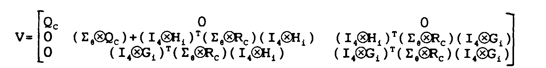
- the matrix Q C being positive semi-defined, it is often chosen diagonal, these diagonal coefficients being noted q ii for i ⁇ ⁇ 1,2,3,4 ⁇ .
- the variable to be regulated is the stator voltage V S. It is therefore necessary to limit the variations of this quantity and make it close to its set value V C as quickly as possible.
- the significant weighting of the stator voltage V S through the coefficient q 22 induces a large gain on the voltage, which limits these variations.
- the weighting coefficient q 44 on the integral of the error e between the set value V C and the stator voltage V S influences the speed with which the set value V C is caught up.
- the larger the value q 44 the faster the stator voltage V s meets the setpoint value V c .
- the electrical power P and the speed ⁇ have a stabilizing role.
- the gains on the speed ⁇ and the active power P are too large, a variation in the frequency of the network, which has a great influence on these two quantities, then has repercussions on the stator voltage V S to be regulated.
- One way of limiting the influence of this disturbance on the stator voltage V S is therefore to reduce the gains on the speed ⁇ and the electric power P.
- the weighting coefficients q 11 and q 33 are taken zero.
Description
La présente invention concerne un dispositif de régulation de la tension statorique d'un alternateur couplé à un réseau électrique, ce dispositif résultant d'une approximation linéaire de l'alternateur couplé au réseau électrique autour d'un point de fonctionnement nominal défini par plusieurs paramètres de fonctionnement de l'alternateur et comportant plusieurs boucles de contre-réaction associées à des gains respectifs agissant sur plusieurs variables d'état mesurées en sortie de l'alternateur ainsi que sur l'intégrale d'une erreur de consigne définie par la différence entre la tension statorique et une valeur de consigne, pour définir à partir de la valeur de consigne, une variable de commande de l'alternateur appliquée à l'entrée de celui-ci pour maintenir la valeur de la tension statorique proche de la valeur de consigne.The present invention relates to a device for regulation of the stator voltage of an alternator coupled to an electrical network, this resulting device of a linear approximation of the alternator coupled to electrical network around an operating point nominal defined by several operating parameters of the alternator and comprising several loops of feedback associated with respective acting gains on several state variables measured at the output of the alternator as well as on the integral of an error of setpoint defined by the difference between the voltage stator and a setpoint, to define from the setpoint, a control variable of the alternator applied to the input of it for keep the value of the stator voltage close to the setpoint.
L'invention s'applique en particulier aux groupes turbo-alternateurs couplés à un réseau électrique et équipés d'un régulateur de vitesse indépendant. Dans une telle régulation, l'objectif est d'agir sur la tension d'excitation de l'alternateur afin d'assurer, quel que soit le point de fonctionnement dans lequel se trouve la machine, la stabilité de l'alternateur, encore appelé système dans la suite de la description, le maintien de la tension statorique à une valeur voisine de la tension de consigne, et enfin des performances satisfaisantes dans le cas d'échelon de tension de consigne de courts-circuits, de report de charge ou encore de variation de fréquence du réseau.The invention applies in particular to turbo-generator sets coupled to an electrical network and equipped with an independent cruise control. In such regulation, the objective is to act on the tension excitation of the alternator to ensure, whatever either the operating point in which the machine, alternator stability, also called system in the following description, maintaining the stator voltage at a value close to the voltage of setpoint, and finally satisfactory performance in the case of short-circuit setpoint voltage step, load transfer or frequency variation of the network.
La difficulté liée à la conception de régulateurs de tension est qu'ils doivent apporter une solution à des perturbations de natures très différentes, les solutions apportées à ces différents problèmes ayant parfois des effets antagonistes. The difficulty of designing regulators of tension is that they have to provide a solution to very different types of disturbance, solutions to these different problems having sometimes antagonistic effects.
On connaít actuellement différentes méthodes de conception de régulateurs de tension, comme par exemple la méthode de placement des pôles, la commande optimale linéaire quadratique ou encore la synthèse dite H-infini. Cependant, ces différentes méthodes ne sont pas totalement satisfaisantes puisque les régulateurs obtenus offrent une assez mauvaise robustesse paramétrique, c'est-à-dire qu'ils sont très sensibles aux erreurs commises sur les valeurs des paramètres de modélisation ou aux variations de ceux-ci.We currently know different methods of design of voltage regulators, such as the pole placement method, optimal linear control quadratic or the so-called H-infinite synthesis. However, these different methods are not totally satisfactory since the regulators obtained offer a fairly poor parametric robustness, i.e. that they are very sensitive to mistakes made on values of modeling parameters or variations of these.
Le but de la présente invention est donc de fournir un dispositif de régulation de tension permettant de répondre aux exigences de stabilité quel que soit le point de fonctionnement du système, et qui de plus soit robuste vis-à-vis des incertitudes paramétriques dues à la modélisation et aux modifications de la topologie du réseau électrique.The object of the present invention is therefore to provide a voltage regulation device allowing meet the stability requirements whatever the point of operation of the system, and which moreover is robust against parametric uncertainties due to the modeling and modifications of the topology of the electrical network.
A cet effet, la présente invention a pour objet un dispositif de régulation de la tension statorique d'un alternateur couplé à un réseau électrique, ce dispositif résultant d'une approximation linéaire de l'alternateur couplé au réseau électrique autour d'un point de fonctionnement nominal défini par plusieurs paramètres de fonctionnement de l'alternateur et comportant plusieurs boucles de contre-réaction associées à des gains respectifs agissant sur plusieurs variables d'état mesurées en sortie de l'alternateur ainsi que sur l'intégrale d'une erreur de consigne définie par la différence entre la tension statorique et une valeur de consigne, pour définir à partir de la valeur de consigne, une variable de commande de l'alternateur appliquée à l'entrée de celui-ci pour maintenir la valeur de la tension statorique proche de la valeur de consigne, caractérisé en ce que les gains du dispositif sont obtenus par minimisation de l'espérance mathématique d'un critère quadratique qui est fonction d'un vecteur d'état regroupant les dérivées par rapport au temps des variables d'état de l'alternateur et l'erreur de consigne et de la dérivée par rapport au temps de la variable de commande, ces variables étant respectivement l'état et l'entrée d'un modèle linéaire, appelé système augmenté, dont la matrice d'état et la matrice d'entrée dépendent de plusieurs des paramètres de l'alternateur et en ce que les gains sont déterminés pour minimiser en outre les sensibilités du vecteur d'état et de la dérivée par rapport au temps de la variable de commande relativement à de petites variations d'au moins l'un desdits plusieurs paramètres de l'alternateur autour du point de fonctionnement nominal créant ainsi une désensibilisation de l'alternateur régulé vis-à-vis desdits plusieurs paramètres.To this end, the subject of the present invention is a device for regulating the stator voltage of a alternator coupled to an electrical network, this device resulting from a linear approximation of the alternator coupled to the electrical network around an operating point nominal defined by several operating parameters of the alternator and having several loops of feedback associated with respective gains acting on several state variables measured at output of the alternator as well as on the integral of an error of setpoint defined by the difference between the stator voltage and a setpoint, to define from the set value, an alternator control variable applied to the entrance of it to maintain the value of the stator voltage close to the value of setpoint, characterized in that the gains of the device are obtained by minimizing the mathematical expectation of a quadratic criterion which is a function of a vector state grouping the derivatives with respect to the time of alternator status variables and setpoint error and the derivative with respect to time of the variable of command, these variables being the state and the input of a linear model, called the augmented system, whose state matrix and input matrix depend on several of the alternator parameters and that the gains are determined to further minimize sensitivities of the state vector and the derivative with respect to command variable time relative to small variations of at least one of said several parameters of the alternator around the nominal operating point thus creating a desensitization of the regulated alternator with respect to said several parameters.
Le dispositif de régulation peut également comporter une ou plusieurs des caractéristiques suivantes :
- ledit critère quadratique est fonction des dérivées partielles du vecteur d'état et de la dérivée par rapport au temps de la variable de commande par rapport aux paramètres de l'alternateur et la désensibilisation de l'alternateur régulé est réalisée par minimisation dudit critère quadratique ;
- le modèle linéaire duquel résultent les variables d'état utilisées dans le vecteur d'état est un modèle réduit à un ordre inférieur d'un modèle linéaire complet par une méthode de réalisation équilibrée consistant à minimiser une norme de la différence entre la matrice de transfert du modèle complet et celle du modèle réduit ;
- les gains sont déterminés par une méthode itérative consistant à réaliser à chaque étape une synthèse des gains par une méthode de commande linéaire quadratique gaussienne, consistant à minimiser un critère quadratique, appliquée à un modèle augmenté fonction d'une représentation d'état du dispositif de régulation obtenu avec les gains calculés à l'étape précédente et de la modélisation linéaire du système augmenté ;
- chaque étape de synthèse des gains est suivie par une réduction à un ordre inférieur de la représentation d'état associée à ces gains par une méthode de réalisation équilibrée ;
- les variables d'état sont la vitesse angulaire, la tension statorique et la puissance électrique.
- said quadratic criterion is a function of the partial derivatives of the state vector and of the derivative with respect to time of the control variable with respect to the parameters of the alternator and the desensitization of the regulated alternator is carried out by minimization of said quadratic criterion;
- the linear model from which result the state variables used in the state vector is a model reduced to a lower order of a complete linear model by a balanced realization method consisting in minimizing a norm of the difference between the transfer matrix of the complete model and that of the reduced model;
- the gains are determined by an iterative method consisting in carrying out at each stage a synthesis of the gains by a method of linear gaussian quadratic control, consisting in minimizing a quadratic criterion, applied to an augmented model as a function of a state representation of the device regulation obtained with the gains calculated in the previous step and from the linear modeling of the augmented system;
- each step of synthesis of the gains is followed by a reduction to a lower order of the state representation associated with these gains by a balanced production method;
- the state variables are the angular velocity, the stator voltage and the electric power.
La présente invention sera mieux comprise à la lecture de la description qui va suivre, donnée uniquement à titre d'exemple et faite en se référant aux dessins sur lesquels :
- la figure 1 est un organigramme d'une procédure itérative mise en oeuvre pour la détermination des gains du dispositif de régulation, et
- la figure 2 est un schéma synoptique d'un alternateur régulé utilisant un dispositif de régulation selon l'invention.
- FIG. 1 is a flow diagram of an iterative procedure implemented for determining the gains of the regulation device, and
- Figure 2 is a block diagram of a regulated alternator using a regulating device according to the invention.
Dans la description qui va suivre, l'alternateur est modélisé ou approximé suivant le modèle connu de l'alternateur connecté à un réseau infini. Dans ce cas, les paramètres de ce système sont entièrement déterminés à partir du point de fonctionnement défini par la puissance active P, la puissance réactive Q, la tension statorique Vs et la longueur de la ligne X.In the description which follows, the alternator is modeled or approximated according to the known model of the alternator connected to an infinite network. In this case, the parameters of this system are entirely determined from the operating point defined by the active power P, the reactive power Q, the stator voltage V s and the length of the line X.
Ainsi, dans cette modélisation, l'ensemble des points de fonctionnement admissibles peuvent être définis à partir de ces quatre grandeurs, les variations de ces grandeurs correspondant aux variations paramétriques du système.Thus, in this modeling, all of the admissible operating points can be defined from these four quantities, the variations of these quantities corresponding to the parametric variations of the system.
Le modèle défini précédemment permet de déterminer des gains notés KΩ, KV, KP, et KI du dispositif de régulation, utilisés dans des boucles de contre-réaction en combinaison avec des variables d'état mesurées à la sortie de l'alternateur afin de définir à partir d'une valeur de consigne VC une variable u de commande de l'alternateur, comme cela est représenté sur la figure 2 et sera décrit plus en détail dans la suite de la description.The model defined above makes it possible to determine gains noted K Ω , K V , K P , and K I of the regulation device, used in feedback loops in combination with state variables measured at the output of the alternator in order to define from a setpoint V C a variable u for controlling the alternator, as shown in FIG. 2 and will be described in more detail in the following description.
Afin d'obtenir un modèle linéaire aussi fiable que possible, un modèle complet non linéaire d'ordre cinq est tout d'abord obtenu de manière classique à partir des équations régissant le fonctionnement de l'alternateur connecté au réseau infini.In order to obtain such a reliable linear model as possible, a complete nonlinear model of order five is first of all obtained in a conventional manner from equations governing the operation of the alternator connected to the infinite network.
Ce modèle est linéarisé autour d'un point de
fonctionnement nominal afin de déterminer un modèle linéaire
complet d'ordre cinq, qui peut s'exprimer pour de
petites variations par la représentation d'état suivante
:
La signification physique des variables d'état de ce modèle est sans intérêt pour la suite de la description, aussi elle ne sera pas détaillée ici. De plus, ces variables d'état ne sont pas mesurables.The physical meaning of state variables of this model is irrelevant for the rest of the description, so it will not be detailed here. In addition, these state variables are not measurable.
Pour la détermination des gains KΩ, KV, KP et KI du dispositif de régulation, on préfère utiliser des variables d'état mesurables telles que la vitesse angulaire Ω, la tension statorique Vs et la puissance électrique P. C'est sur ces variables d'état que les gains agissent dans le dispositif de régulation.For the determination of the gains K Ω , K V , K P and K I of the regulation device, it is preferable to use measurable state variables such as the angular speed Ω, the stator voltage V s and the electric power P. C ' It is on these state variables that the gains act in the regulation device.
Pour ce faire, on réduit le modèle précédent à un modèle linéaire d'ordre trois, suivant la méthode classique de la réalisation équilibrée.To do this, we reduce the previous model to a linear model of order three, according to the method classic of balanced achievement.
Cette méthode consiste à minimiser dans l'espace de Hardy une norme notée H-infini, de la différence entre la matrice de transfert du modèle linéaire complet et celle du modèle réduit. This method consists in minimizing in space of Hardy a norm noted H-infinity, of the difference between the transfer matrix of the complete linear model and that of the model.
La réduction du modèle linéaire d'ordre cinq à
un modèle d'ordre trois et un changement de base, opération
classique en la matière, permettent d'exprimer le
modèle linéaire d'ordre trois de l'alternateur connecté au
réseau infini au point de fonctionnement choisi sous la
forme suivante :
Comme cela est connu dans l'état de la technique, afin de maintenir la valeur de la variable de sortie à réguler, supposée ici être la tension statorique notée VS, égale à la valeur de consigne notée VC, il est souhaitable que la variable u de commande de l'alternateur, engendrée par le dispositif de régulation ait un effet intégral.As is known in the state of the art, in order to maintain the value of the output variable to be regulated, assumed here to be the stator voltage denoted V S , equal to the reference value denoted V C , it is desirable that the variable u of alternator control, generated by the regulating device has an integral effect.
Pour ce faire, et de manière classique, on
procède à une augmentation du modèle (1) en faisant intervenir
dans un modèle dit "augmenté" une erreur de consigne
notée e égale à la différence entre la tension statorique
VS et la valeur de la consigne Vc. Ce modèle augmenté est
alors de la forme :
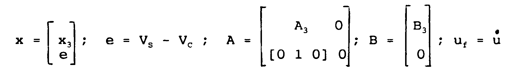
Dans ce modèle, la variable uf est la dérivée par rapport au temps de la variable u de commande appliquée par le dispositif de régulation à l'entrée de commande de l'alternateur. Le vecteur x est un vecteur d'état du système et il regroupe les variables d'état mesurées en sortie de l'alternateur, ainsi que l'erreur e de consigne. Ce vecteur d'état x est alors dit augmenté. In this model, the variable u f is the derivative with respect to time of the control variable u applied by the regulating device to the control input of the alternator. The vector x is a state vector of the system and it groups together the state variables measured at the output of the alternator, as well as the reference error e. This state vector x is then said to be increased.
Etant donnée la conception du dispositif de
régulation selon l'invention schématisé sur la figure 2,
cette variable uf est de la forme :
Pour obtenir la variable u de commande, il suffit d'intégrer la variable uf par rapport au temps dans l'expression de la loi de commande précédente.To obtain the command variable u, it suffices to integrate the variable u f with respect to time in the expression of the preceding control law.
Selon la présente invention, les gains KΩ, KV, KP et KI sont déterminés pour minimiser l'espérance mathématique de l'énergie associée au vecteur d'état augmenté x et à la variable uf pour des valeurs incertaines des paramètres de fonctionnement du système, voisines de leur valeur nominale. Dans la modélisation, les paramètres de fonctionnement du système sont regroupés sous la forme d'un vecteur paramètre noté = (P, VS, Q, X).According to the present invention, the gains K Ω , K V , K P and K I are determined to minimize the mathematical expectation of the energy associated with the increased state vector x and with the variable u f for uncertain values of the parameters. of the system, close to their nominal value. In the modeling, the operating parameters of the system are grouped in the form of a vector parameter noted = (P, V S , Q, X).
Pour ce faire, on considère le modèle augmenté
(2) dans lequel les matrices d'état A() et d'entrée B()
sont fonctions des différents paramètres = (P, VS, Q, X)
du système. Ce modèle augmenté, appelé système augmenté,
s'écrit alors sous la forme suivante :
Pour la détermination des gains KΩ, KV, KP, et KI du dispositif de régulation, on supposera dans cette modélisation que les paramètres = (P, VS, Q, X) du système sont invariants dans le temps et indépendants au sens probabiliste de l'état initial x0.For the determination of the gains K Ω , K V , K P , and K I of the regulation device, it will be assumed in this modeling that the parameters = (P, V S , Q, X) of the system are invariant in time and independent in the probabilistic sense of the initial state x 0 .
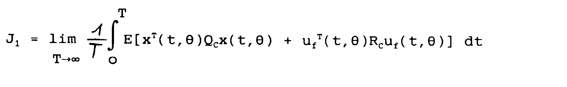
A partir de cette modélisation (3), on définit
alors un critère quadratique J1 défini par la relation
suivante :
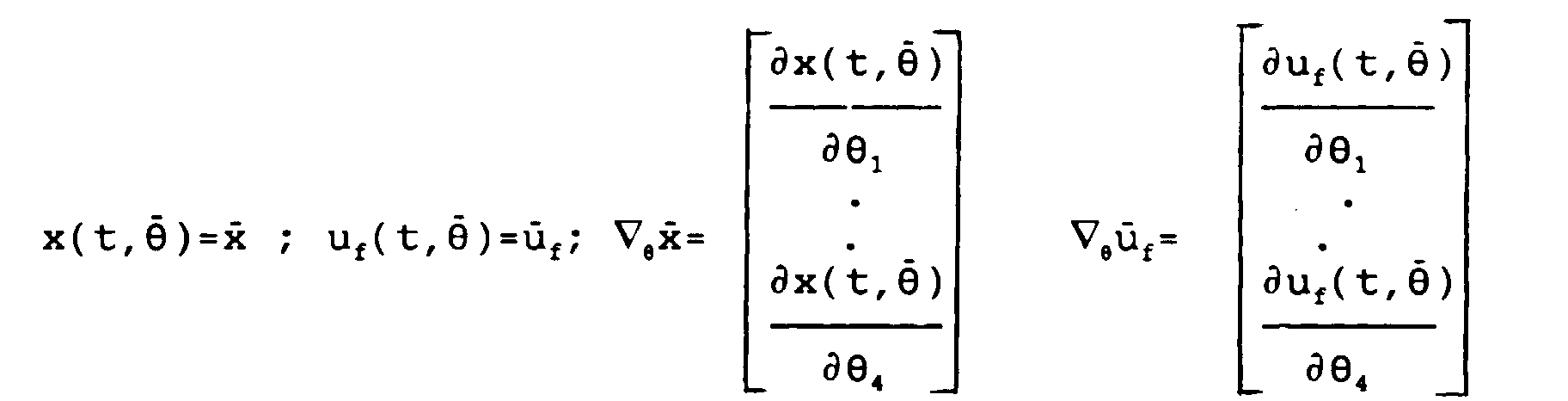
A partir du critère quadratique J1, on définit un
nouveau critère quadratique, noté Jz, en effectuant un
développement limité au premier ordre du vecteur d'état x
et de la variable uf autour d'une valeur
Le résultat de ce calcul classique de développement
limité au premier ordre s'exprime de la façon suivante
:

![]()
![]()
![]()
![]()
Dans cette expression, les premier et second termes représentent respectivement les énergies correspondant au vecteur d'état x et à la variable uf, dérivée de la variable u de commande alors que les troisième et quatrième termes qui sont fonction des dérivées partielles du vecteur d'état x et de la variable uf par rapport aux paramètres P, VS, Q, X du système représentent respectivement les énergies des sensibilités du vecteur d'état x et de la variable uf par rapport à de petites variations des paramètres P, VS, Q, X du système regroupés dans le vecteur = (P, VS, Q, X).In this expression, the first and second terms represent respectively the energies corresponding to the state vector x and to the variable u f , derived from the control variable u while the third and fourth terms which are a function of the partial derivatives of the vector d state x and of the variable u f with respect to the parameters P, V S , Q, X of the system represent respectively the energies of the sensitivities of the state vector x and of the variable u f with respect to small variations of the parameters P , V S , Q, X of the system grouped in the vector = (P, V S , Q, X).
La minimisation du critère quadratique JZ conduit donc à minimiser la somme de ces quatre énergies. Les deux derniers termes, que l'on ne retrouve pas dans les critères quadratiques classiques assurent un effet de désensibilisation du système régulé vis-à-vis des variations du vecteur regroupant les paramètres P, VS, Q et X.The minimization of the quadratic criterion J Z therefore leads to minimizing the sum of these four energies. The last two terms, which are not found in the classic quadratic criteria, ensure a desensitization effect of the regulated system with respect to the variations of the vector grouping the parameters P, V S , Q and X.
La minimisation du critère J2 ne peut être effectuée directement, et les gains KΩ, KV, KP, KI sont obtenus par une procédure itérative.The minimization of the criterion J 2 cannot be carried out directly, and the gains K Ω , K V , K P , K I are obtained by an iterative procedure.
Pour ce faire, on définit à chaque étape i des
gains notés Ki = (KΩ, KV, KP, KI)i, définissant un régulateur
dont une représentation d'état s'exprime de manière
classique sous la forme suivante :
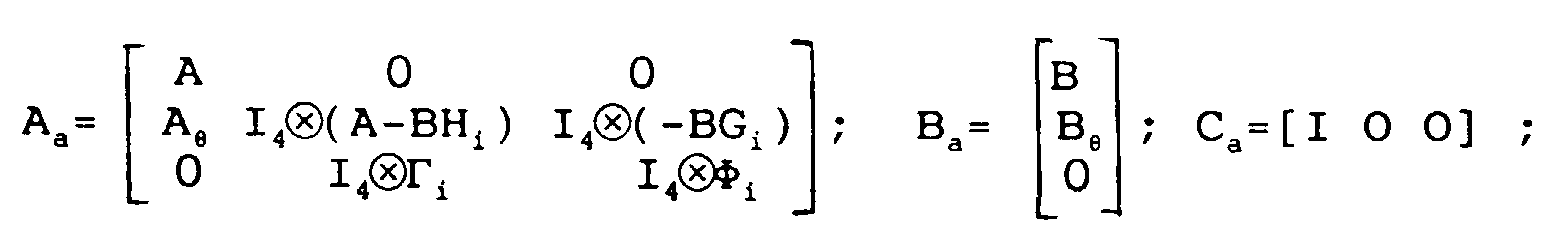
A partir de cette représentation d'état (4) et
du modèle linéaire (3) on construit un nouveau système linéaire
(5) dit "augmenté" d'un ordre supérieur, s'exprimant
sous la forme suivante :

Dans cette expression, les variables et leurs
dérivées partielles sont évaluées en =
En fonction de cette nouvelle modélisation linéaire (5) et en supposant que les gains Ki sont connus, on définit un critère J3i associé et obtenu en appliquant de manière classique la commande linéaire quadratique gaussienne au système modélisé en (5).As a function of this new linear modeling (5) and assuming that the gains K i are known, we define a criterion J 3i associated and obtained by applying in a conventional manner the quadratic linear Gaussian command to the system modeled in (5).
Le critère J3i associé s'exprime sous la forme :

La minimisation du critère J3i fournit les gains Ki+1 de l'étape i+1 suivante.The minimization of the criterion J 3i provides the gains K i + 1 of the next step i + 1.
Afin d'initialiser la procédure itérative, la détermination des gains initiaux K0 est obtenue de manière simple. En effet, comme on l'a vu précédemment, les variables d'état Ω, VS, P du système sont entièrement mesurables, les gains K0 sont ainsi obtenus par retour d'état sur le modèle linéaire (3).In order to initialize the iterative procedure, the determination of the initial gains K 0 is obtained in a simple manner. Indeed, as we saw previously, the state variables Ω, V S , P of the system are entirely measurable, the gains K 0 are thus obtained by return of state on the linear model (3).
Comme on l'a vu précédemment, la loi de commande est telle que la variable uf s'exprime linéairement en fonction des coefficients du vecteur x. Par conséquent, dans la modélisation (4) associée à ce régulateur, les termes Φ, Γ et G sont nuls. Ainsi, à la première itération, l'état Xa du système augmenté (5) est constitué uniquement de x et σ. Le critère quadratique à minimiser J30 correspondant porte sur ces deux grandeurs et sur la variable uf.As we saw previously, the control law is such that the variable u f is expressed linearly as a function of the coefficients of the vector x. Consequently, in the modelization (4) associated with this regulator, the terms Φ, Γ and G are null. Thus, at the first iteration, the state X a of the augmented system (5) consists only of x and σ. The corresponding quadratic criterion to minimize J 30 relates to these two quantities and to the variable u f .
La procédure itérative d'obtention des gains Ki
est représentée sur la figure 1. A partir du système
nominal correspondant au modèle linéaire augmenté (3)
établi à l'étape 10, on détermine à l'étape 12, comme cela
vient d'être expliqué, les gains initiaux notés K0 par
application d'une commande linéaire quadratique sur le
modèle linéaire augmenté (3) et minimisation du critère
quadratique associé.The iterative procedure for obtaining the gains K i is represented in FIG. 1. From the nominal system corresponding to the augmented linear model (3) established in
Pour le calcul des gains Ki+1 suivant, on détermine à l'étape 14 une représentation d'état (4) du dispositif de régulation associé aux gains Ki supposé connu puis on détermine à l'étape 16 un modèle augmenté (5), à partir duquel on minimise de façon classique en utilisant la théorie de la commande linéaire quadratique gaussienne un critère quadratique J3i, ce qui permet d'obtenir les gains Ki+1.For the calculation of the following gains K i + 1 , a state representation is determined in step 14 (4) of the regulation device associated with the gains K i assumed to be known, then an augmented model is determined in step 16 (5 ), from which we conventionally minimize using the theory of the Gaussian quadratic linear command a quadratic criterion J 3i , which makes it possible to obtain the gains K i + 1 .
Afin d'éviter que l'ordre de la représentation d'état (4) du dispositif de régulation n'augmente au cours de la mise en oeuvre répétée des étapes itératives, l'ordre de la représentation d'état associée au dispositif de régulation de paramètres Ki+1 est réduit à chaque itération à l'étape 18 par la méthode de réalisation équilibrée décrite précédemment.In order to prevent the order of the state representation (4) of the regulating device from increasing during the repeated implementation of the iterative steps, the order of the state representation associated with the regulating device of parameters K i + 1 is reduced at each iteration in step 18 by the balanced embodiment method described above.
Après cette étape, un critère de convergence
détermine à l'étape 20, s'il est nécessaire ou non d'affiner
encore la détermination des gains Ki+1. Si tel est le
cas, une nouvelle itération de la procédure itérative est
mise en oeuvre à l'étape 22.After this step, a convergence criterion determines in
A titre indicatif, concernant les alternateurs de type 1300 MW, compte tenu de la réduction de l'ordre de la représentation d'état du dispositif de régulation à chaque étape, on obtient à la fin de la procédure itérative un dispositif de régulation d'ordre deux. Le tracé des lieux de Bode des transferts entre les variables d'état et la variable de commande montre qu'il est possible de réduire encore l'ordre du dispositif de régulation et en particulier de l'amener à zéro en prenant comme paramètre de régulation KΩ, KV, KP, KI la moyenne respective de chacun des gains obtenus lors de la procédure itérative, ces paramètres étant considérés comme des fonctions de la fréquence.As an indication, concerning 1300 MW type alternators, taking into account the reduction in the order of the state representation of the regulation device at each stage, at the end of the iterative procedure, a regulation device is obtained. order two. The plot of the Bode locations of transfers between the state variables and the control variable shows that it is possible to further reduce the order of the regulation device and in particular to bring it to zero by taking as regulation parameter K Ω , K V , K P , K I the respective average of each of the gains obtained during the iterative procedure, these parameters being considered as functions of the frequency.
Sur la figure 2, on a représenté un schéma
synoptique de la régulation d'un alternateur par un dispositif
de régulation selon l'invention, ainsi on retrouve
un alternateur 50 associé à un dispositif d'excitation
50A. A la sortie de l'alternateur 50 sont mesurées par des
capteurs adaptés classiques (non représentés) les variables
d'état Ω, VS, P.In Figure 2, there is shown a block diagram of the regulation of an alternator by a regulating device according to the invention, thus we find an
A chacune de ces valeurs mesurées correspond une
boucle de contre-réaction noté respectivement 52, 54 et 56
munie chacune d'un amplificateur 58, 60 et 62 dont le gain
correspond aux gains KΩ, KV, KP correspondant respectivement
à chacune des variables d'état Ω, Vs, P.Each of these measured values corresponds to a feedback loop denoted respectively 52, 54 and 56 each provided with an
On notera que la puissance mécanique Pm est considérée comme une entrée perturbatrice qui n'est pas prise en compte pour la conception du dispositif de régulation. Toutefois, afin de réduire l'effet d'une variation de la puissance mécanique Pm sur la tension statorique Vs, la puissance P dans le dispositif de régulation représenté sur la figure 2 est diminuée en 64 de la puissance mécanique Pm mesurée sur la turbine d'entraínement de l'alternateur.It will be noted that the mechanical power P m is considered to be a disturbing input which is not taken into account for the design of the regulation device. However, in order to reduce the effect of a variation in the mechanical power P m on the stator voltage V s , the power P in the regulation device shown in FIG. 2 is reduced at 64 by the mechanical power P m measured on the alternator drive turbine.
Par ailleurs, le régulateur est conçu en négligeant
le dispositif d'excitation 50A qui, en réalité,
s'intercale entre la sortie du régulateur et l'entrée de
l'alternateur 50. Comme cela est représenté sur la figure
2, un dispositif 50B de compensation de l'excitatrice est
disposé si nécessaire entre la sortie du régulateur et
l'entrée du dispositif d'excitation 50A.Furthermore, the regulator is designed by neglecting
the excitation device 50A which, in reality,
is inserted between the regulator output and the input of
the
Une boucle de contre-réaction supplémentaire 66
achemine la valeur de la tension statorique Vs à un dispositif
de soustraction 68 calculant la différence de cette
valeur et de la valeur de consigne Vc. Le résultat de cette
différence est ensuite injecté dans un intégrateur 70
avant d'être multiplié par un amplificateur 72 dont le
gain correspond au gain KI calculé comme expliqué précédemment.An
La variable u de commande est alors formée à
partir des sorties des différents amplificateurs grâce à
des dispositifs sommateurs et soustracteurs 74 à 80
suivant un agencement classique permettant de mettre en
oeuvre la loi de commande définie plus haut et résultant
de l'intégration de l'expression de uf. La variable u est
alors envoyée à l'alternateur 50 au travers des dispositifs
de compensation de l'excitatrice 50B et d'excitation
50A.The control variable u is then formed from the outputs of the various amplifiers by means of summing and subtracting
Dans la pratique, bien qu'un tel régulateur
puisse être réalisé à partir de dispositifs analogiques,
on utilisera de préférence un calculateur numérique, par
exemple un ordinateur programmé afin d'engendrer la variable
u de commande en fonction des variables d'état Ω, Vs,
P mesurées en sortie de l'alternateur 50 ainsi que de la
consigne Vc.In practice, although such a regulator can be produced from analog devices, a digital computer is preferably used, for example a computer programmed to generate the control variable u as a function of the state variables Ω, V s , P measured at the output of the
Dans le cas précis d'un alternateur, parmi les quatre paramètres P, VS, Q, X de l'alternateur tels que définis précédemment et utilisés dans la modélisation, la tension statorique VS et la longueur de ligne X sont ceux qui influent le plus sur la stabilité du système. En effet, il est difficile de stabiliser un alternateur connecté à un réseau quand la longueur de ligne X est grande ou encore quand la tension statorique VS est basse. Par contre, les variations de puissance active P et de puissance réactive Q ont une influence moins significative sur la stabilité. Ces différentes considérations permettent de concevoir un dispositif de régulation désensibilisé uniquement par rapport à la longueur de ligne X et la tension statorique VS. Ainsi, pour les calculs, le vecteur est réduit à deux composantes.In the specific case of an alternator, among the four parameters P, V S , Q, X of the alternator as defined above and used in the modeling, the stator voltage V S and the line length X are those which influence the most about system stability. In fact, it is difficult to stabilize an alternator connected to a network when the line length X is large or even when the stator voltage V S is low. On the other hand, variations in active power P and reactive power Q have a less significant influence on stability. These different considerations make it possible to design a desensitized regulation device only with respect to the line length X and the stator voltage V S. Thus, for calculations, the vector is reduced to two components.
En ce qui concerne le choix des matrices de pondération QC et RC, la matrice QC étant semi-définie positive, elle est souvent choisie diagonale, ces coefficients diagonaux étant notés qii pour i∈{1,2,3,4}.Regarding the choice of the weighting matrices Q C and R C , the matrix Q C being positive semi-defined, it is often chosen diagonal, these diagonal coefficients being noted q ii for i∈ {1,2,3,4 }.
On sait que lors de la conception d'un dispositif de régulation par commande linéaire quadratique, il faut systématiquement commencer par pondérer la variable à réguler (dans ce cas, la tension statorique Vs) ainsi que l'intégrale de l'erreur de consigne e. Les autres variables d'état (ici Ω et P) ont uniquement un rôle stabilisateur et ne sont éventuellement pondérées que dans le but d'améliorer les marges de stabilité.We know that when designing a regulation device by quadratic linear control, we must systematically start by weighting the variable to be regulated (in this case, the stator voltage V s ) as well as the integral of the setpoint error e. The other state variables (here Ω and P) have only a stabilizing role and are possibly only weighted in order to improve the stability margins.
Dans le cas présent, la variable à réguler est la tension statorique VS. Il faut donc limiter les variations de cette grandeur et la rendre voisine de sa valeur de consigne VC le plus rapidement possible. La pondération importante de la tension statorique VS à travers le coefficient q22 induit un grand gain sur la tension, ce qui limite ces variations. Le coefficient de pondération q44 sur l'intégrale de l'erreur e entre la valeur de consigne VC et la tension statorique VS influe sur la rapidité avec laquelle la valeur de consigne VC est rattrappée. Ainsi, plus la valeur q44 est grande, plus la tension statorique Vs rejoint rapidement la valeur de consigne Vc.In the present case, the variable to be regulated is the stator voltage V S. It is therefore necessary to limit the variations of this quantity and make it close to its set value V C as quickly as possible. The significant weighting of the stator voltage V S through the coefficient q 22 induces a large gain on the voltage, which limits these variations. The weighting coefficient q 44 on the integral of the error e between the set value V C and the stator voltage V S influences the speed with which the set value V C is caught up. Thus, the larger the value q 44 , the faster the stator voltage V s meets the setpoint value V c .
Par ailleurs, la puissance électrique P et la vitesse Ω ont un rôle stabilisateur. De plus, on constate que si les gains sur la vitesse Ω et la puissance active P sont trop importants, une variation de la fréquence du réseau, qui influe beaucoup sur ces deux grandeurs, se répercute alors sur la tension statorique VS à réguler. Une façon de limiter l'influence de cette perturbation sur la tension statorique VS est donc de réduire les gains sur la vitesse Ω et la puissance électrique P. Ainsi, les coefficients de pondération q11 et q33 sont pris nuls.Furthermore, the electrical power P and the speed Ω have a stabilizing role. In addition, it is noted that if the gains on the speed Ω and the active power P are too large, a variation in the frequency of the network, which has a great influence on these two quantities, then has repercussions on the stator voltage V S to be regulated. One way of limiting the influence of this disturbance on the stator voltage V S is therefore to reduce the gains on the speed Ω and the electric power P. Thus, the weighting coefficients q 11 and q 33 are taken zero.
Concernant la matrice de pondération RC, celle-ci est prise égale à un nombre réel positif. Sa valeur est choisie de façon à obtenir sur l'ensemble du domaine de fonctionnement une marge de retard suffisante pour garantir la robustesse vis-à-vis des dynamiques négligées lors de la linéarisation du modèle de l'alternateur. Ainsi, plus le nombre choisi pour la matrice RC est grand, plus la marge de retard est grande.Concerning the weighting matrix R C , this is taken equal to a positive real number. Its value is chosen so as to obtain a sufficient delay margin over the entire operating range to guarantee robustness with respect to the dynamics neglected during the linearization of the alternator model. Thus, the larger the number chosen for the matrix R C , the greater the margin of delay.
Pour le choix des différents paramètres, il est nécessaire de prendre en compte le fait que les performances obtenues dépendent des coefficients de la matrice QC, alors que la robustesse non paramétrique dépend du choix de la matrice RC et la robustesse paramétrique dépend du choix de la matrice Σ et augmente avec celle-ci.For the choice of the different parameters, it is necessary to take into account the fact that the performances obtained depend on the coefficients of the matrix Q C , while the non parametric robustness depends on the choice of the matrix R C and the parametric robustness depends on the choice of the matrix Σ and increases with it.
Du fait de l'existence d'un compromis entre la robustesse et la performance, les coefficients de ces matrices ne sont pas déterminés indépendamment les uns des autres mais dans le but de réaliser le meilleur compromis possible.Due to the existence of a compromise between the robustness and performance, the coefficients of these matrices are not determined independently of each others but in order to achieve the best compromise possible.
Claims (6)
- Arrangement for regulating the stator voltage (variable VS to be controlled) of an alternator (50) coupled to an electric network, this arrangement resulting in a linear approximation of the alternator coupled to the electric network around a nominal operating point defined by a number of operating parameters (P, VS, Q, X) of the alternator and comprising a number of associated counter-reaction loops (52, 54, 56, 66) having respective gains (KΩ, KV, KP, KI) acting on a number of variables of state (Ω, VS, P) measured at the output of the alternator as well as on the integral of a design error (e) defined by the difference between the stator voltage (VS) and a design value (Vc) for defining, starting from the design value (VC), a variable (u) for controlling the alternator applied to the input of the latter for maintaining the value of the stator voltage (VS) near the design value (VC), characterised in that the gains (KΩ, KV, KP, KI) of the arrangement are obtained by minimisation of the mathematical expectation of a quadratic criterion (J2) which is a function of a state vector (x) regrouping the derivatives with respect to time of the state variables (Ω, VS, P) of the alternator and the design error (e) and of the derivative (uf) with respect to time of the control variable (u), these variables being respectively the state at the input of a linear model (3), defined as an augmented system, of which the state matrix (A()) and the input matrix (B()) depend on a number of parameters (P, VS, Q, X) of the alternator and in that the gains (KΩ, KV, KP, KI) are determined to minimise in addition the sensitivities of the state vector (x) and of the derivative with respect to time of the control variable (u) relative to small variations in at least one of the said number of parameters (P, VS, Q, X) of the alternator around the nominal operating point thus creating a desensitisation of the regulated alternator with respect to the said number of parameters (P, VS, Q, X).
- Regulating arrangement according to claim 1, characterised in that the said quadratic criterion (J2) is a function of the partial derivatives of the state vector (x) and of the derivative with respect to time of the control variable (u) with respect to the parameters (P, VS, Q, X) of the alternator and in that the desensitisation of the regulated alternator is achieved by minimisation of the said quadratic criterion (J2).
- Regulating arrangement according to any one of the foregoing claims, characterised in that the linear model (1) of the said resultant of the state variables (Ω, VS, P) used in the state vector (x) is a model reduced to a lower order of a complete linear model (O) by a balanced method of realisation consisting in minimising a norm of the difference between the transfer matrix of the complete model and that of the reduced model.
- Regulating arrangement according to any one of the foregoing claims, characterised in that the gains (KΩ, KV, KP, KI) are determined by an iterative method consisting in realising at each stage a synthesis of the gains ((KΩ, KV, KP, KI)i+1) by a gaussian linear quadratic control method consisting in minimising a quadratic criterion (J3i) applied to an augmented model (5) as a function of a representation of the state (4) of the regulating arrangement obtained with the gains ((KΩ, KV, KP, KI)i) calculated at the preceding stage and of the linear modelling (3) of the augmented system.
- Regulating arrangement according to claim 4, characterised in that each stage of the synthesis of the gains ((KΩ, KV, KP, KI) is followed by a reduction to a lower order of the representation of the state (4) associated with these gains by a balanced method of realisation.
- Regulating arrangement according to any one of the foregoing claims, characterised in that the variables of state are the angular velocity (Ω), the stator voltage (VS) and the electric power (P).
Applications Claiming Priority (2)
| Application Number | Priority Date | Filing Date | Title |
|---|---|---|---|
| FR9414400A FR2727584A1 (en) | 1994-11-30 | 1994-11-30 | DEVICE FOR DESENSITIZED REGULATION OF THE STATOR VOLTAGE OF AN ALTERNATOR |
| FR9414400 | 1994-11-30 |
Publications (2)
| Publication Number | Publication Date |
|---|---|
| EP0715400A1 EP0715400A1 (en) | 1996-06-05 |
| EP0715400B1 true EP0715400B1 (en) | 1998-04-01 |
Family
ID=9469338
Family Applications (1)
| Application Number | Title | Priority Date | Filing Date |
|---|---|---|---|
| EP95402685A Expired - Lifetime EP0715400B1 (en) | 1994-11-30 | 1995-11-29 | Desensitized stator voltage control device for an alternator |
Country Status (4)
| Country | Link |
|---|---|
| US (1) | US5606248A (en) |
| EP (1) | EP0715400B1 (en) |
| DE (1) | DE69501938T2 (en) |
| FR (1) | FR2727584A1 (en) |
Families Citing this family (7)
| Publication number | Priority date | Publication date | Assignee | Title |
|---|---|---|---|---|
| GB0004018D0 (en) * | 2000-02-22 | 2000-04-12 | Lucas Industries Ltd | Control circuit for electrical generator |
| US6445169B1 (en) * | 2000-12-29 | 2002-09-03 | Volterra Semiconductor Corporation | Lag compensating controller having an improved transient response |
| EP2549342A1 (en) * | 2011-07-20 | 2013-01-23 | Alstom Technology Ltd. | Regulation method |
| EP2549343A1 (en) * | 2011-07-20 | 2013-01-23 | Alstom Technology Ltd. | Regulation method |
| FR2985621B1 (en) * | 2012-01-05 | 2014-09-05 | Acsysteme | METHOD FOR CONTROLLING THE STATORIC VOLTAGE OF A TURBO-ALTERNATOR, SYSTEM AND PROGRAM PRODUCT THEREOF |
| JP6510959B2 (en) * | 2015-11-19 | 2019-05-08 | 株式会社三井E&Sホールディングス | Wind turbine drive train control system |
| CN109617140A (en) * | 2018-12-12 | 2019-04-12 | 云南电网有限责任公司电力科学研究院 | A kind of Large Hydropower Station governor parameter optimization method |
Family Cites Families (4)
| Publication number | Priority date | Publication date | Assignee | Title |
|---|---|---|---|---|
| DE3108915A1 (en) * | 1981-03-09 | 1982-09-16 | Siemens AG, 1000 Berlin und 8000 München | METHOD AND DEVICE FOR REGULATING A TURBO SET |
| CA2005092A1 (en) * | 1988-12-29 | 1990-06-29 | David A. Fox | Generator voltage regulation with non-linear compensation |
| US5373227A (en) * | 1993-03-26 | 1994-12-13 | Micron Semiconductor, Inc. | Control circuit responsive to its supply voltage level |
| US5548205A (en) * | 1993-11-24 | 1996-08-20 | National Semiconductor Corporation | Method and circuit for control of saturation current in voltage regulators |
-
1994
- 1994-11-30 FR FR9414400A patent/FR2727584A1/en active Granted
-
1995
- 1995-11-29 US US08/564,019 patent/US5606248A/en not_active Expired - Lifetime
- 1995-11-29 EP EP95402685A patent/EP0715400B1/en not_active Expired - Lifetime
- 1995-11-29 DE DE69501938T patent/DE69501938T2/en not_active Expired - Lifetime
Also Published As
| Publication number | Publication date |
|---|---|
| FR2727584A1 (en) | 1996-05-31 |
| FR2727584B1 (en) | 1997-02-14 |
| US5606248A (en) | 1997-02-25 |
| EP0715400A1 (en) | 1996-06-05 |
| DE69501938D1 (en) | 1998-05-07 |
| DE69501938T2 (en) | 1998-09-24 |
Similar Documents
| Publication | Publication Date | Title |
|---|---|---|
| EP2756577B1 (en) | Stabilization of an electrical dc grid | |
| EP0579948B1 (en) | Control system for an asynchronous motor | |
| EP0715400B1 (en) | Desensitized stator voltage control device for an alternator | |
| WO2006131664A1 (en) | Device for automatically adjusting servo controls of a movement mechanical simulator and an associated device | |
| FR2911698A1 (en) | Electromagnetic actuator controlling device for aircraft, has comparison module comparing current and quadrature component data with current values of stator current axis and quadrature current of stator current to provide variation data | |
| EP0576947B1 (en) | Motor system of an electric vehicle | |
| WO2012066233A9 (en) | Method and device for active control of mechanical vibrations by implementation of a controller consisting of a central corrector and a youla parameter | |
| CA2630893A1 (en) | Method for regulating voltage or current in an rlc filter, recording medium and vehicles for said method | |
| EP0770430A1 (en) | Process and device for driving ultrasonic power transducers | |
| FR3070056A1 (en) | MIXED AIRCRAFT ENGINE CONTROL SYSTEM AND METHOD OF ADJUSTING THE SAME | |
| WO2019149907A1 (en) | Method for regulating operating parameters of a nuclear reactor and corresponding nuclear reactor | |
| EP0469508B1 (en) | Method and device for estimating the magnetic reduction flux of an asynchronous motor, especially with a view of the motor control by flux regulation | |
| EP0085008A1 (en) | Analogous control system for servoloops controlling the rotational position of a motor with a variable inertial load | |
| EP2549342A1 (en) | Regulation method | |
| EP4133339A1 (en) | Use of generalised homogeneity to improve a pid control command | |
| FR2692688A1 (en) | A method of controlling a continuous process comprising a model optimization phase and a regulation phase. | |
| EP0858155A1 (en) | Method for the regulation of a rotating machine, regulation system to implement said method and rotating machine equipped with such a system | |
| EP0702451A1 (en) | Synchronous motor control device | |
| WO2018024977A1 (en) | Method for controlling a multi-level modular converter | |
| FR2834249A1 (en) | Equipment for controlling the operating point of propulsion unit with infinitely variable transmission, comprises supervisor which assists the control unit to produce operating point commands | |
| FR2475313A1 (en) | Automatic regulation of turbo-alternator sets - by sensing and processing alternator parameters, using reference circuit prior to supporting adjustable regulator | |
| EP0419644A1 (en) | Self-adaptive control process for piloting a physical system. | |
| WO2008084150A1 (en) | Method for controlling the torque of an alternator in an automotive vehicle and system for implementing said method | |
| EP2783461B1 (en) | Method for controlling a power train and corresponding control system | |
| EP4020738A1 (en) | Methods and system for jointly controlling a voltage in a medium-voltage branch and in a plurality of low-voltage branches |
Legal Events
| Date | Code | Title | Description |
|---|---|---|---|
| PUAI | Public reference made under article 153(3) epc to a published international application that has entered the european phase |
Free format text: ORIGINAL CODE: 0009012 |
|
| AK | Designated contracting states |
Kind code of ref document: A1 Designated state(s): DE SE |
|
| 17P | Request for examination filed |
Effective date: 19960420 |
|
| RIN1 | Information on inventor provided before grant (corrected) |
Inventor name: HOURY,MARIE-PIERRE Inventor name: HENICHE, ANNISSA Inventor name: BOURLES, HENRI |
|
| GRAG | Despatch of communication of intention to grant |
Free format text: ORIGINAL CODE: EPIDOS AGRA |
|
| GRAG | Despatch of communication of intention to grant |
Free format text: ORIGINAL CODE: EPIDOS AGRA |
|
| GRAH | Despatch of communication of intention to grant a patent |
Free format text: ORIGINAL CODE: EPIDOS IGRA |
|
| 17Q | First examination report despatched |
Effective date: 19970908 |
|
| GRAH | Despatch of communication of intention to grant a patent |
Free format text: ORIGINAL CODE: EPIDOS IGRA |
|
| GRAA | (expected) grant |
Free format text: ORIGINAL CODE: 0009210 |
|
| AK | Designated contracting states |
Kind code of ref document: B1 Designated state(s): DE SE |
|
| REF | Corresponds to: |
Ref document number: 69501938 Country of ref document: DE Date of ref document: 19980507 |
|
| PLBE | No opposition filed within time limit |
Free format text: ORIGINAL CODE: 0009261 |
|
| STAA | Information on the status of an ep patent application or granted ep patent |
Free format text: STATUS: NO OPPOSITION FILED WITHIN TIME LIMIT |
|
| 26N | No opposition filed | ||
| PGFP | Annual fee paid to national office [announced via postgrant information from national office to epo] |
Ref country code: DE Payment date: 20131106 Year of fee payment: 19 Ref country code: SE Payment date: 20131108 Year of fee payment: 19 |
|
| REG | Reference to a national code |
Ref country code: DE Ref legal event code: R119 Ref document number: 69501938 Country of ref document: DE |
|
| REG | Reference to a national code |
Ref country code: SE Ref legal event code: EUG |
|
| PG25 | Lapsed in a contracting state [announced via postgrant information from national office to epo] |
Ref country code: SE Free format text: LAPSE BECAUSE OF NON-PAYMENT OF DUE FEES Effective date: 20141130 |
|
| PG25 | Lapsed in a contracting state [announced via postgrant information from national office to epo] |
Ref country code: DE Free format text: LAPSE BECAUSE OF NON-PAYMENT OF DUE FEES Effective date: 20150602 |