EP0715084B1 - Konischer Drehflügelantrieb und seine Verwendung zur Steuerung eines Scharniers eines Flugzeuges - Google Patents
Konischer Drehflügelantrieb und seine Verwendung zur Steuerung eines Scharniers eines Flugzeuges Download PDFInfo
- Publication number
- EP0715084B1 EP0715084B1 EP95402648A EP95402648A EP0715084B1 EP 0715084 B1 EP0715084 B1 EP 0715084B1 EP 95402648 A EP95402648 A EP 95402648A EP 95402648 A EP95402648 A EP 95402648A EP 0715084 B1 EP0715084 B1 EP 0715084B1
- Authority
- EP
- European Patent Office
- Prior art keywords
- rotary actuator
- inner body
- panel
- force transmission
- blades
- Prior art date
- Legal status (The legal status is an assumption and is not a legal conclusion. Google has not performed a legal analysis and makes no representation as to the accuracy of the status listed.)
- Expired - Lifetime
Links
- 230000005540 biological transmission Effects 0.000 claims description 32
- 230000007423 decrease Effects 0.000 claims description 5
- 239000013529 heat transfer fluid Substances 0.000 claims description 4
- 230000003750 conditioning effect Effects 0.000 claims description 3
- 230000003247 decreasing effect Effects 0.000 claims 1
- 238000009434 installation Methods 0.000 description 4
- 238000005452 bending Methods 0.000 description 2
- 230000000295 complement effect Effects 0.000 description 2
- 238000002513 implantation Methods 0.000 description 2
- RZVHIXYEVGDQDX-UHFFFAOYSA-N 9,10-anthraquinone Chemical compound C1=CC=C2C(=O)C3=CC=CC=C3C(=O)C2=C1 RZVHIXYEVGDQDX-UHFFFAOYSA-N 0.000 description 1
- 230000004913 activation Effects 0.000 description 1
- 230000000903 blocking effect Effects 0.000 description 1
- 238000005253 cladding Methods 0.000 description 1
- 238000006073 displacement reaction Methods 0.000 description 1
- 239000012530 fluid Substances 0.000 description 1
- 239000000543 intermediate Substances 0.000 description 1
Images

Classifications
-
- F—MECHANICAL ENGINEERING; LIGHTING; HEATING; WEAPONS; BLASTING
- F15—FLUID-PRESSURE ACTUATORS; HYDRAULICS OR PNEUMATICS IN GENERAL
- F15B—SYSTEMS ACTING BY MEANS OF FLUIDS IN GENERAL; FLUID-PRESSURE ACTUATORS, e.g. SERVOMOTORS; DETAILS OF FLUID-PRESSURE SYSTEMS, NOT OTHERWISE PROVIDED FOR
- F15B15/00—Fluid-actuated devices for displacing a member from one position to another; Gearing associated therewith
- F15B15/08—Characterised by the construction of the motor unit
- F15B15/12—Characterised by the construction of the motor unit of the oscillating-vane or curved-cylinder type
Definitions
- the invention relates to a rotary actuator.
- a rotary actuator comprising an inner body and at least one body outside coaxially mounted one inside the other of so that they can be rotated relative, each of the cylinder bodies carrying pallets arranged alternately to define two series sealed variable volume control chambers.
- Such a jack is known from document US-A-2 870 748.
- the invention also relates to a control surface. aircraft comprising at least one hinged panel of which pivoting is controlled by such a rotary actuator.
- the inner body and the outer body of the rotary cylinders have one and the other a cylindrical configuration and the height of pallets carried by each of these bodies is uniform from one end to the other of these pallets.
- Number of pallets fitted to the actuator mainly depends on the amplitude of the pivoting movement that is desired order.
- the cylinders rotary knobs are used to control movements of pivoting of limited amplitude between two parts. They have the advantage of having a very low space since they can be placed along the axis relative pivoting between the parts. By comparing, control of the same movement using a cylinder linear requires mounting the cylinder on one of the parts, perpendicular to the pivot axis and the connect to the other room using a mechanism including at least one articulated link.
- control surfaces present rigidities different from those of the wing, it there are differences between deformations in flight control surfaces and sails. For reasons aerodynamics, the maximum values of these differences should be as small as possible. This can lead to carrying out each control under the form of several panels, which must then be ordered independently of each other. In the assumption that we would use two cylinders cylindrical by panel, installation of cylinders in the steering would require the presence of sixteen or twenty four levels depending on whether the control surface cut into two or three panels.
- the main object of the invention is a original design rotary actuator with in particular, for a given diametrical size, a significantly higher power than a cylinder classic cylindrical rotary.
- the invention also relates to a jack rotary whose original design reduces the number of stages necessary for the transmission of forces between the cylinder and the parts and, consequently, the cost of an installation using such cylinders.
- the invention also relates to a jack rotary whose original design reduces torsional deformations of at least one of the bodies inside and outside of the cylinder, relative to the cylinders conventional rotary.
- a rotary actuator comprising an inner body and at least one outer body coaxially mounted one inside the other so as to define between them at least one annular space, first pallets and second integral pallets the inner body and the outer body respectively and arranged alternately in said annular space, to alternately define firsts and second volume tight control chambers variable, including alternating pressure control relative rotation between the inner bodies and exterior, characterized in that at least one interior and exterior body has a section scalable, so that the first and second pallets have a height which decreases by one end to end of these pallets.
- a rotary actuator meeting this definition will be called hereinafter "conical rotary actuator”. This designation, which stems from the evolving nature of the section of the annular space formed between the bodies inside and outside of the cylinder, must not be considered to limit the configuration of this annular space with a precise geometric shape.
- the outer body is cylindrical and has a constant section while the inner body has an evolving section.
- the inner body can in particular present a substantially frustoconical part and a substantially cylindrical part extending a relatively small diameter end of the part substantially frustoconical.
- the relatively large end of the substantially frustoconical part of the inner body then has an outer diameter substantially equal to the inside diameter of the outside body.
- the inner body constitutes the rotor cylinder while the outer body is the stator.
- a reverse arrangement can however be adopted in some applications.
- the internal body of the jack is advantageously a tubular body. This feature allows to connect the inner body to a conditioning circuit in temperature, ensuring circulation, inside of the cylinder of a heat transfer fluid capable of reheat or cool the cylinder as required of use.
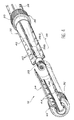
- the rotary actuator comprises two bodies exteriors mounted coaxially on two parts of the inner body, each of these two parts bearing second pallets arranged alternately with the first pallets carried by each body exteriors.
- the rotary actuator then advantageously has symmetry with respect to a cutting median plane the inner body in the middle.
- the heights of the first and second pallets decrease from the median plane of the cylinder towards its ends.
- the internal body comprises, between the two parts carrying the second pallets, a central force transmission part.
- each of the outer bodies includes a terminal part transmission of forces, close to each ends of the cylinder.
- the invention also relates to a control surface.
- aircraft comprising at least one hinged panel on a rear spar of a wing element aircraft, around a hinge axis substantially parallel to this rear spar, and means for panel pivot control around this axis of articulation, characterized in that the means pivot control include at least one cylinder conical rotary machine according to the invention, housed in the panel according to its axis of articulation.
- each of the first bearings is carried by the beam back so you can turn around a first axis perpendicular to the spar and passing through the axis of articulation of the panel.
- each of the first bearings is engaged on the terminal parts transmission of cylinder forces by first connecting means in rotation around the axis of articulation of the panel.
- first connecting means in rotation around the axis of articulation of the panel.
- second connecting means in rotation about the axis of articulation, by which the second landing is engaged on the central part of force transmission from the jack.
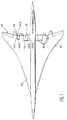
- each elevons 12 and 14 is cut into three panels adjacent articulated, of substantially equal dimensions, in the direction defined by the rear spar 18. These three panels are designated by the references 12a, 12b and 12c for internal elevons 12 and 14a, 14b and 14c for the middle elevons 14.
- each of the panels 12a, 1b and 12c and 14a, 14b and 14c is controlled by a conical rotary actuator 16. More specifically, the three rotary cylinders conical 16 associated with each of elevons 12 and 14 are identical.
- each of the rotary cylinders conical 16 has two transmission end parts of efforts which are connected by two bearings 26 to the rear spar 18 of the corresponding half-wing 10.
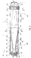
- the rotary actuator conical 16 comprises a body tubular interior 32 forming rotor and two bodies tubular exteriors 34 forming a stator, mounted coaxially.
- each outer body 34 is identical and each of them is received on one of the parts tubular 38 of the inner body 32, so that delimit between this part 38 and the external body 34 corresponding to a tight annular space vis-à-vis from the outside.
- each outer body 34 has on its outer surface a terminal part 62 for transmitting forces, intended to be engaged on the corresponding bearing 26, in a way that will be described further detail later.
- Each of the tubular parts 38 of the body interior 32 carries pallets on its exterior surface 40 oriented radially outwards (figure 5). These pallets 40 are regularly distributed over the periphery of the tubular part 38. They are by example of four in the embodiment represented. The edges of the turned pallets 40 towards the corresponding external body 34 carry seals 42 ensuring the tightness of the contact between these two rooms.
- each of the external bodies 34 has pallets on its inner surface 44 oriented radially inwards. Pallets 44 are regularly distributed around the axis of the cylinder and their number is the same as that of the pallets 40, so that the pallets 40 and 44 are arranged alternately around the cylinder axis. In the embodiment shown, each of the bodies 34 therefore also has four pallets 44. The edges of the pallets 44 turned towards the body interior 32 have seals 46 which are in tight contact with the outer surface of the corresponding tubular part 38 of the interior body 32.
- the end of relatively large diameter of the part 38a substantially frustoconical of each of the tubular parts 38 has an outside diameter substantially equal to inner body diameter 34 received on this part tubular 38.
- Each of the pallets 40 and 44 has an approximately triangular shape. A calculation simple shows that for the same surface activates pallets and for a cylinder with the same outer diameter, the shape given to the pallets 40 and 44 in the conical rotary actuator according to the invention increases the cylinder's efficiency by 16.7% by compared to a design cylindrical rotary actuator traditional.
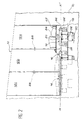
- Each of the bearings 26 is mounted on the beam rear 18 of the corresponding half-wing 10 so that it can rotate around a perpendicular axis yy ' to the rear spar 18 and passing through the axis hinge xx 'of the corresponding panel such as the panel 12a in FIG. 5.
- the arrangement which has just been described ensures the translational connection of the actuator 16 and the spar rear 18 of the corresponding half-wing 10, all by allowing a relative displacement necessary for the bending of the half-wing.
- the bearing 20 is fixed on a force introduction fitting 78, itself fixed to the front spar 22 and to the rib strong median 24 (Figure 2) of the corresponding panel 12a.
- the hollow character of the body inner tubular 32 of each of the cylinders 16 allows to connect the internal bodies 32 in series by a line 86 belonging to a conditioning circuit in temperature of a heat transfer fluid. It is thus possible to circulate in the cylinders a heat transfer fluid allowing in particular to heat these to facilitate their activation when the outside temperature is too low.
- At least one shackle 88 is preferably placed between each pair of adjacent elevon panels, substantially mid-cord of these panels. Shackles 88 allow besides avoiding the rotation of each of the panels around its central rib 24, which could occur due to its rotational drive by a single level 20.
Landscapes
- Engineering & Computer Science (AREA)
- Physics & Mathematics (AREA)
- Fluid Mechanics (AREA)
- Mechanical Engineering (AREA)
- General Engineering & Computer Science (AREA)
- Transmission Devices (AREA)
- Actuator (AREA)
Claims (16)
- Drehzylinder mit einem Innengehäuse (32) und wenigstens einem Außengehäuse (34), das eine koaxial in das andere montiert, sodass sie zwischen sich wenigstens einen ringförmigen Raum definieren, und mit ersten Flügeln (40) und zweiten Flügeln (44), abwechselnd jeweils mit dem Innengehäuse und mit dem Außengehäuse verbunden und in dem genannten ringförmigen Raum so angeordnet, dass sie dort wechselweise dichte erste (48) und zweite (50) Steuerkammern mit variablem Volumen bilden, deren abwechselndes Unterdrucksetzen eine relative Drehung zwischen dem Innengehäuse (32) und dem Außengehäuse (34) bewirkt,
dadurch gekennzeichnet,
dass wenigstens eines der Innen- (32) und Außengehäuse (34) einen sich verändernden Querschnitt aufweist, so dass die ersten (40) und zweiten Flügel (44) eine Höhe aufweisen, die von einem Ende dieser Flügel zum anderen abnimmt. - Drehzylinder nach Anspruch 1, dadurch gekennzeichnet, dass das Außengehäuse (34) einen konstanten Querschnitt aufweist, während das Innengehäuse (32) einen sich verändernden Querschnitt aufweist.
- Drehzylinder nach Anspruch 2, dadurch gekennzeichnet, dass das Innengehäuse (32) einen im wesentlichen kegelstumpfartigen Teil (38a) und einen im wesentlichen zylindrischen Teil (38b) aufweist, der ein Ende mit relativ kleinem Durchmesser des im wesentlichen kegelstumpfartigen Teils verlängert.
- Drehzylinder nach Anspruch 3, dadurch gekennzeichnet, dass ein Ende mit relativ großem Durchmesser des im wesentlichen kegelstumpfartigen Teils des Innengehäuses (32) einen Außendurchmesser aufweist, der im wesentlichen gleich dem Innendurchmesser des Außengehäuses (34) ist.
- Drehzylinder nach einem der vorhergehenden Ansprüche, dadurch gekennzeichnet, dass das Innengehäuse (32) und das Außengehäuse (34) jeweils einen Rotor und einen Stator bilden.
- Drehzylinder nach einem der vorhergehenden Ansprüche, dadurch gekennzeichnet, dass das Innengehäuse (32) ein rohrörmiges Gehäuse ist, das mit einem Temperaturkonditionierungskreis (86) eines flüssigen Kühlmittels verbunden ist.
- Drehzylinder nach einem der vorhergehenden Ansprüche, dadurch gekennzeichnet, dass er zwei Außengehäuse (34) umfasst, die koaxial auf zwei Teile (38) des Innengehäuses (32) montiert sind, wobei jedes dieser beiden Teile erste Flügel (40) trägt, die abwechselnd mit den zweiten Flügeln (44) angeordnet sind, die von jedem der Außengehäuse (34) getragen werden.
- Drehzylinder nach Anspruch 7, dadurch gekennzeichnet, dass er in Bezug auf eine Mittelebene, die das Gehäuse (32) in seiner Mitte durchschneidet, eine Symmetrie aufweist.
- Drehzylinder nach einem der Ansprüche 7 und 8, dadurch gekennzeichnet, dass die Höhen der ersten und zweiten Flügel (40,44) von der Mittelebene zu seinen Enden hin abnehmen.
- Drehzylinder nach einem der Ansprüche 7 bis 9, dadurch gekennzeichnet, dass das Innengehäuse (32) zwischen den die ersten Flügel (40) tragenden Teilen (38) einen Kraftübertragungs-Mittelteil (36) umfasst, wobei jedes der Außengehäuse (34) einen Kraftübertragungs-Endteil (62) in der Nähe von jedem der Enden des Zylinders aufweist.
- Flugzeugruder mit wenigstens einer Klappe (12a,12b, 12c), angelenkt an einem hinteren Träger (18) eines Flugzeugflügelelements, um eine im wesentlichen zu diesem hinteren Träger parallele Schwenkachse (xx') herum, und Schwenksteuerungseinrichtungen der Klappe um diese Schwenkachse herum, dadurch gekennzeichnet, dass die Schwenksteuerungseinrichtungen wenigstens einen Zylinder (16) nach einem der vorhergehenden Ansprüche umfasst, der entsprechend der genannten Schwenkachse (xx') in die Klappe (12a,12b,12c) eingebaut ist.
- Flugzeugruder nach den kombinierten Ansprüchen 10 und 11, dadurch gekennzeichnet, dass die Kraftübertragungs-Endteile (62) des Drehzylinders (16) in erste Lager (26) montiert sind, die durch den hinteren Träger (18) getragen werden, und dass der Kraftübertragungs-Mittelteil (36) des Drehzylinders in ein zweites Lager (20) montiert ist, das durch die Klappe (12a) getragen wird.
- Flugzeugruder nach Anspruch 12, dadurch gekennzeichnet, dass jedes der ersten Lager (26) durch den hinteren Träger (18) so getragen wird, dass es sich um eine erste, zum Träger senkrechte Achse (yy') drehen kann, die durch die Schwenkachse (xx') der Klappe verläuft.
- Flugzeugruder nach einem der Ansprüche 12 und 13, dadurch gekennzeichnet, dass jedes der ersten Lager (26) durch erste Einrichtungen (76) zur Drehverbindung um die Schwenkachse der Klappe mit den Kraftübertragungs-Endteilen (62) des Zylinders in Eingriff ist, und dass das zweite Lager (20) durch zweite Einrichtungen (80) zur Drehverbindung um die Schwenkachse mit dem Kraftübertragungs-Mittelteil (36) in Eingriff ist.
- Flugzeugruder nach einem der Ansprüche 12 bis 14, dadurch gekennzeichnet, dass eines der ersten Lager (26) durch erste Verbindungseinrichtungen zur Translation entsprechend der Schwenkachse der Klappe mit einem der Kraftübertragungs-Endteile (62) des Zylinders in Eingriff ist, und dass das zweite Lager (20) durch zweite Verbindungseinrichtungen (84) zur Translation entsprechend der Schwenkachse mit dem Kraftübertragungs-Mittelteil (36) in Eingriff ist.
- Flugzeugruder nach einem der Ansprüche 11 bis 15, dadurch gekennzeichnet, dass das Ruder (12) wenigstens zwei Klappen (12a,12b) umfasst, die durch wenigstens ein Schäkel bzw. einen Bügel (88) miteinander verbunden sind, wobei in jede der Klappen ein Drehzylinder (16) eingebaut ist.
Applications Claiming Priority (3)
| Application Number | Priority Date | Filing Date | Title |
|---|---|---|---|
| FR9414222A FR2727477A1 (fr) | 1994-11-28 | 1994-11-28 | Verin rotatif conique et son application a la commande d'une gouverne d'aeronef |
| FR9414222 | 1994-11-28 | ||
| US08/562,761 US5722616A (en) | 1994-11-28 | 1995-11-27 | Conical rotary actuator and its application to the control of a rudder |
Publications (2)
| Publication Number | Publication Date |
|---|---|
| EP0715084A1 EP0715084A1 (de) | 1996-06-05 |
| EP0715084B1 true EP0715084B1 (de) | 2000-05-17 |
Family
ID=26231568
Family Applications (1)
| Application Number | Title | Priority Date | Filing Date |
|---|---|---|---|
| EP95402648A Expired - Lifetime EP0715084B1 (de) | 1994-11-28 | 1995-11-23 | Konischer Drehflügelantrieb und seine Verwendung zur Steuerung eines Scharniers eines Flugzeuges |
Country Status (3)
| Country | Link |
|---|---|
| US (1) | US5722616A (de) |
| EP (1) | EP0715084B1 (de) |
| FR (1) | FR2727477A1 (de) |
Families Citing this family (28)
| Publication number | Priority date | Publication date | Assignee | Title |
|---|---|---|---|---|
| NL1003171C2 (nl) * | 1996-05-20 | 1997-11-21 | Arie Van Wieringen Video Film | Vaancilinder. |
| US6672540B1 (en) | 2002-12-03 | 2004-01-06 | Rockwell Collins, Inc. | Actuator for aircraft stabilizers with a failure responsive lock control mechanism |
| GB2470345A (en) * | 2009-03-17 | 2010-11-24 | Vestas Wind Systems A S | Rotary actuator hinge for connecting first and second wind turbine components. |
| GB2472759A (en) | 2009-03-17 | 2011-02-23 | Vestas Wind Sys As | Retractable hinge apparatus for wind turbine control surface |
| FR2992629B1 (fr) * | 2012-06-27 | 2014-09-12 | Airbus Operations Sas | Dispositif de liaison mecanique d'une gouverne a un element structural fixe d'aeronef et element de voilure d'aeronef equipe de ce dispositif |
| US8857757B2 (en) | 2012-08-02 | 2014-10-14 | Bell Helicopter Textron Inc. | Independent blade control system with hydraulic pitch link |
| US9061760B2 (en) | 2012-08-02 | 2015-06-23 | Bell Helicopter Textron Inc. | Independent blade control system with rotary blade actuator |
| US9162760B2 (en) | 2012-08-02 | 2015-10-20 | Bell Helicopter Textron Inc. | Radial fluid device with multi-harmonic output |
| US9376205B2 (en) | 2012-08-02 | 2016-06-28 | Bell Helicopter Textron Inc. | Radial fluid device with variable phase and amplitude |
| US8973864B2 (en) | 2012-08-02 | 2015-03-10 | Bell Helicopter Textron Inc. | Independent blade control system with hydraulic cyclic control |
| US8915176B2 (en) | 2013-02-06 | 2014-12-23 | Woodward, Inc. | Hydraulic blocking rotary actuator |
| US9631645B2 (en) | 2013-02-27 | 2017-04-25 | Woodward, Inc. | Rotary piston actuator anti-rotation configurations |
| US9476434B2 (en) | 2013-02-27 | 2016-10-25 | Woodward, Inc. | Rotary piston type actuator with modular housing |
| US9163648B2 (en) * | 2013-02-27 | 2015-10-20 | Woodward, Inc. | Rotary piston type actuator with a central actuation assembly |
| US9816537B2 (en) * | 2013-02-27 | 2017-11-14 | Woodward, Inc. | Rotary piston type actuator with a central actuation assembly |
| US8955425B2 (en) | 2013-02-27 | 2015-02-17 | Woodward, Inc. | Rotary piston type actuator with pin retention features |
| US9593696B2 (en) * | 2013-02-27 | 2017-03-14 | Woodward, Inc. | Rotary piston type actuator with hydraulic supply |
| US9234535B2 (en) | 2013-02-27 | 2016-01-12 | Woodward, Inc. | Rotary piston type actuator |
| US9915241B2 (en) | 2013-03-14 | 2018-03-13 | Woodward, Inc. | Rotary vane actuator with fluid actuated mechanical lock |
| US9841021B2 (en) | 2013-03-14 | 2017-12-12 | Woodward, Inc. | No corner seal rotary vane actuator |
| JP2016527449A (ja) * | 2013-06-19 | 2016-09-08 | ウッドワード, インコーポレーテッドWoodward, Inc. | 油圧源を備えるロータリ・ピストン型アクチュエータ |
| US9957831B2 (en) * | 2014-07-31 | 2018-05-01 | The Boeing Company | Systems, methods, and apparatus for rotary vane actuators |
| US9950782B2 (en) | 2014-10-31 | 2018-04-24 | The Boeing Company | Methods and apparatus for integrating rotary actuators in flight control systems |
| US10220938B2 (en) | 2014-12-11 | 2019-03-05 | Gulfstream Aerospace Corporation | Aircraft, control surface arrangements, and methods of assembling an aircraft |
| US20170323240A1 (en) | 2016-05-06 | 2017-11-09 | General Electric Company | Computing system to control the use of physical state attainment with inspection |
| US10633080B2 (en) * | 2016-07-22 | 2020-04-28 | The Boeing Company | Electronically controlled rotary actuator for an aircraft control surface |
| US11199248B2 (en) | 2019-04-30 | 2021-12-14 | Woodward, Inc. | Compact linear to rotary actuator |
| WO2021207482A1 (en) | 2020-04-08 | 2021-10-14 | Woodward, Inc. | Rotary piston type actuator with a central actuation assembly |
Family Cites Families (13)
| Publication number | Priority date | Publication date | Assignee | Title |
|---|---|---|---|---|
| US2870748A (en) * | 1953-06-30 | 1959-01-27 | North American Aviation Inc | Rotary actuator |
| DE1024804B (de) * | 1956-09-18 | 1958-02-20 | Ernst Heinkel Fahrzeugbau G M | Hydraulischer Klappenantrieb, insbesondere fuer Flugzeuge |
| US3020008A (en) * | 1957-10-01 | 1962-02-06 | Houdaille Industries Inc | Control surface actuator damper hinge |
| US2951470A (en) * | 1957-10-15 | 1960-09-06 | Richard E Self | Oscillating actuator |
| US2984221A (en) * | 1958-07-01 | 1961-05-16 | Douglas Aircraft Co Inc | Rotary actuator |
| US2966144A (en) * | 1958-07-15 | 1960-12-27 | C L Norsworthy Jr | Oscillatory actuator |
| US3053232A (en) * | 1960-09-08 | 1962-09-11 | Thompson Ramo Wooldridge Inc | Damper reservoir gas actuator |
| DE3565157D1 (en) * | 1984-07-20 | 1988-10-27 | Tol O Matic Inc | Rotary actuator |
| US4738415A (en) * | 1986-10-17 | 1988-04-19 | Weyer Paul P | Hinge line flight actuator |
| FR2606363B1 (fr) * | 1986-11-07 | 1989-03-03 | Aerospatiale | Systeme pour la commande des volets hypersustentateurs d'un aeronef |
| US4838104A (en) * | 1987-08-07 | 1989-06-13 | Pneumo Abex Corporation | Center mounted and center drive helical spline actuator |
| US4945779A (en) * | 1987-12-22 | 1990-08-07 | Hr Textron, Inc. | Ball screw rotary actuator |
| US5098043A (en) * | 1990-02-27 | 1992-03-24 | Grumman Aerospace Corporation | Integrated power hinge actuator |
-
1994
- 1994-11-28 FR FR9414222A patent/FR2727477A1/fr active Granted
-
1995
- 1995-11-23 EP EP95402648A patent/EP0715084B1/de not_active Expired - Lifetime
- 1995-11-27 US US08/562,761 patent/US5722616A/en not_active Expired - Lifetime
Also Published As
| Publication number | Publication date |
|---|---|
| FR2727477A1 (fr) | 1996-05-31 |
| EP0715084A1 (de) | 1996-06-05 |
| FR2727477B1 (de) | 1997-02-14 |
| US5722616A (en) | 1998-03-03 |
Similar Documents
| Publication | Publication Date | Title |
|---|---|---|
| EP0715084B1 (de) | Konischer Drehflügelantrieb und seine Verwendung zur Steuerung eines Scharniers eines Flugzeuges | |
| EP1188933B1 (de) | Steuervorrichtung für verstellbare Leitschaufeln | |
| EP2435302B1 (de) | Verstellvorrichtung der propellerblätter eines turbofantriebwerks mittels festem stellglied | |
| EP2435303B1 (de) | Verstellvorrichtung der propellerblätter eines turbofantriebwerks mittels samt den propellerblättern rotierendem stellglied | |
| EP1346910B1 (de) | Homokinetisch angetriebener Rotor für ein Drehflügelflugzeug | |
| EP0029773B1 (de) | Schwenkbare Schubdüse für Strahlantrieb | |
| WO2010136686A2 (fr) | Dispositif pour la commande de l'orientation des pales de soufflante d'un turbopropulseur | |
| FR3001264A1 (fr) | Systeme pour changer le pas des pales d'une helice. | |
| EP3260715B1 (de) | Ring für lager einer antriebseinheit eines wasserfahrzeugs, das einen in segmente unterteilten aktiven teil umfasst | |
| EP0680876A1 (de) | Eingelassender Gegendrehmomentrotor mit Schaufeln mit eingebautem Spiel | |
| EP0021901A1 (de) | Kompakt-Gelenkrotor für Drehflüger | |
| CA2610056C (fr) | Turbopropulseur comportant un ensemble de pales a orientation reglable | |
| CH711021A1 (fr) | Propulseur pour bateau. | |
| CA2647164A1 (fr) | Profil aerodynamique ou hydrodynamique pouvant etre deforme de maniere continue et controlee | |
| FR2742726A1 (fr) | Dispositif de repliage d'une pale d'un rotor de giravion | |
| EP0457646A1 (de) | Taumelscheibenvorrichtung mit in Nicken und Rollen ausgekuppelten Gelenken montiert für die Einstellwinkelsteuerung der Rotorblätter eines Drehflügelflugzeuges | |
| CA3146451A1 (fr) | Atterrisseur avec voile de renfort | |
| EP0276188A2 (de) | Elektrohydraulisches Servoventil für die Servosteuerung eines hydraulischen Verbrauchers, insbesondere für Servoregler bei Flugzeugsteuerungen | |
| FR2831934A1 (fr) | Boite de transmission basculante avec dispositif de rattrapage de jeu selon l'axe de basculement | |
| EP0332506B1 (de) | Modularer Manipulator-Arm | |
| EP0549455B1 (de) | Zylindrische Elastomer-Lager-Anlage mit grossem WInkelausschlag | |
| EP0042330B1 (de) | Homokinetische Kupplung | |
| EP4380858A1 (de) | Lüftermodul mit schaufeln mit variabler neigung | |
| EP1451066A1 (de) | Kippgetriebe mit gleitlager-schwenkverbindung | |
| EP0615023A1 (de) | Gerät zum rotationsfähigen Einbau eines Arms oder dergleichen zwischen zwei Teilen eines gabelförmigen Elementes |
Legal Events
| Date | Code | Title | Description |
|---|---|---|---|
| PUAI | Public reference made under article 153(3) epc to a published international application that has entered the european phase |
Free format text: ORIGINAL CODE: 0009012 |
|
| AK | Designated contracting states |
Kind code of ref document: A1 Designated state(s): DE GB IT SE |
|
| 17P | Request for examination filed |
Effective date: 19961112 |
|
| GRAG | Despatch of communication of intention to grant |
Free format text: ORIGINAL CODE: EPIDOS AGRA |
|
| 17Q | First examination report despatched |
Effective date: 19990811 |
|
| GRAG | Despatch of communication of intention to grant |
Free format text: ORIGINAL CODE: EPIDOS AGRA |
|
| GRAH | Despatch of communication of intention to grant a patent |
Free format text: ORIGINAL CODE: EPIDOS IGRA |
|
| GRAH | Despatch of communication of intention to grant a patent |
Free format text: ORIGINAL CODE: EPIDOS IGRA |
|
| GRAA | (expected) grant |
Free format text: ORIGINAL CODE: 0009210 |
|
| AK | Designated contracting states |
Kind code of ref document: B1 Designated state(s): DE GB IT SE |
|
| REF | Corresponds to: |
Ref document number: 69516987 Country of ref document: DE Date of ref document: 20000621 |
|
| RAP2 | Party data changed (patent owner data changed or rights of a patent transferred) |
Owner name: AEROSPATIALE MATRA |
|
| ITF | It: translation for a ep patent filed | ||
| GBT | Gb: translation of ep patent filed (gb section 77(6)(a)/1977) |
Effective date: 20000724 |
|
| PLBE | No opposition filed within time limit |
Free format text: ORIGINAL CODE: 0009261 |
|
| STAA | Information on the status of an ep patent application or granted ep patent |
Free format text: STATUS: NO OPPOSITION FILED WITHIN TIME LIMIT |
|
| 26N | No opposition filed | ||
| REG | Reference to a national code |
Ref country code: GB Ref legal event code: IF02 |
|
| PGFP | Annual fee paid to national office [announced via postgrant information from national office to epo] |
Ref country code: DE Payment date: 20101119 Year of fee payment: 16 |
|
| PGFP | Annual fee paid to national office [announced via postgrant information from national office to epo] |
Ref country code: IT Payment date: 20101126 Year of fee payment: 16 Ref country code: SE Payment date: 20101112 Year of fee payment: 16 Ref country code: GB Payment date: 20101118 Year of fee payment: 16 |
|
| REG | Reference to a national code |
Ref country code: SE Ref legal event code: EUG |
|
| GBPC | Gb: european patent ceased through non-payment of renewal fee |
Effective date: 20111123 |
|
| PG25 | Lapsed in a contracting state [announced via postgrant information from national office to epo] |
Ref country code: IT Free format text: LAPSE BECAUSE OF NON-PAYMENT OF DUE FEES Effective date: 20111123 |
|
| REG | Reference to a national code |
Ref country code: DE Ref legal event code: R119 Ref document number: 69516987 Country of ref document: DE Effective date: 20120601 |
|
| PG25 | Lapsed in a contracting state [announced via postgrant information from national office to epo] |
Ref country code: GB Free format text: LAPSE BECAUSE OF NON-PAYMENT OF DUE FEES Effective date: 20111123 Ref country code: SE Free format text: LAPSE BECAUSE OF NON-PAYMENT OF DUE FEES Effective date: 20111124 |
|
| PG25 | Lapsed in a contracting state [announced via postgrant information from national office to epo] |
Ref country code: DE Free format text: LAPSE BECAUSE OF NON-PAYMENT OF DUE FEES Effective date: 20120601 |