EP0715040B1 - Vorrichtung zum Aufschneiden von Ummantelungen - Google Patents
Vorrichtung zum Aufschneiden von Ummantelungen Download PDFInfo
- Publication number
- EP0715040B1 EP0715040B1 EP95118731A EP95118731A EP0715040B1 EP 0715040 B1 EP0715040 B1 EP 0715040B1 EP 95118731 A EP95118731 A EP 95118731A EP 95118731 A EP95118731 A EP 95118731A EP 0715040 B1 EP0715040 B1 EP 0715040B1
- Authority
- EP
- European Patent Office
- Prior art keywords
- tendon
- cutter
- housing
- arm
- cutting
- Prior art date
- Legal status (The legal status is an assumption and is not a legal conclusion. Google has not performed a legal analysis and makes no representation as to the accuracy of the status listed.)
- Expired - Lifetime
Links
- 210000002435 tendon Anatomy 0.000 claims description 74
- 238000004873 anchoring Methods 0.000 claims description 34
- 239000000463 material Substances 0.000 claims description 4
- 229920003023 plastic Polymers 0.000 claims description 4
- 239000004033 plastic Substances 0.000 claims description 4
- 238000005260 corrosion Methods 0.000 description 4
- 230000007797 corrosion Effects 0.000 description 4
- 230000002787 reinforcement Effects 0.000 description 3
- 239000011435 rock Substances 0.000 description 3
- 229910000831 Steel Inorganic materials 0.000 description 2
- 238000009413 insulation Methods 0.000 description 2
- 238000000034 method Methods 0.000 description 2
- 239000010959 steel Substances 0.000 description 2
- 239000004698 Polyethylene Substances 0.000 description 1
- 229910001315 Tool steel Inorganic materials 0.000 description 1
- 230000003321 amplification Effects 0.000 description 1
- 238000005352 clarification Methods 0.000 description 1
- 238000010276 construction Methods 0.000 description 1
- 230000003247 decreasing effect Effects 0.000 description 1
- 238000011161 development Methods 0.000 description 1
- 230000018109 developmental process Effects 0.000 description 1
- 230000009977 dual effect Effects 0.000 description 1
- 239000004519 grease Substances 0.000 description 1
- 238000009434 installation Methods 0.000 description 1
- 230000014759 maintenance of location Effects 0.000 description 1
- 239000004200 microcrystalline wax Substances 0.000 description 1
- 238000012986 modification Methods 0.000 description 1
- 230000004048 modification Effects 0.000 description 1
- 238000003199 nucleic acid amplification method Methods 0.000 description 1
- -1 polyethylene Polymers 0.000 description 1
- 229920000573 polyethylene Polymers 0.000 description 1
- 230000036316 preload Effects 0.000 description 1
- 230000003014 reinforcing effect Effects 0.000 description 1
- 238000007665 sagging Methods 0.000 description 1
- 238000007789 sealing Methods 0.000 description 1
- 238000000926 separation method Methods 0.000 description 1
Images


Classifications
-
- E—FIXED CONSTRUCTIONS
- E04—BUILDING
- E04G—SCAFFOLDING; FORMS; SHUTTERING; BUILDING IMPLEMENTS OR AIDS, OR THEIR USE; HANDLING BUILDING MATERIALS ON THE SITE; REPAIRING, BREAKING-UP OR OTHER WORK ON EXISTING BUILDINGS
- E04G21/00—Preparing, conveying, or working-up building materials or building elements in situ; Other devices or measures for constructional work
- E04G21/12—Mounting of reinforcing inserts; Prestressing
-
- Y—GENERAL TAGGING OF NEW TECHNOLOGICAL DEVELOPMENTS; GENERAL TAGGING OF CROSS-SECTIONAL TECHNOLOGIES SPANNING OVER SEVERAL SECTIONS OF THE IPC; TECHNICAL SUBJECTS COVERED BY FORMER USPC CROSS-REFERENCE ART COLLECTIONS [XRACs] AND DIGESTS
- Y10—TECHNICAL SUBJECTS COVERED BY FORMER USPC
- Y10S—TECHNICAL SUBJECTS COVERED BY FORMER USPC CROSS-REFERENCE ART COLLECTIONS [XRACs] AND DIGESTS
- Y10S83/00—Cutting
- Y10S83/924—Work wrapped or coated around a core, not part of the machine
-
- Y—GENERAL TAGGING OF NEW TECHNOLOGICAL DEVELOPMENTS; GENERAL TAGGING OF CROSS-SECTIONAL TECHNOLOGIES SPANNING OVER SEVERAL SECTIONS OF THE IPC; TECHNICAL SUBJECTS COVERED BY FORMER USPC CROSS-REFERENCE ART COLLECTIONS [XRACs] AND DIGESTS
- Y10—TECHNICAL SUBJECTS COVERED BY FORMER USPC
- Y10S—TECHNICAL SUBJECTS COVERED BY FORMER USPC CROSS-REFERENCE ART COLLECTIONS [XRACs] AND DIGESTS
- Y10S83/00—Cutting
- Y10S83/929—Particular nature of work or product
- Y10S83/947—Particular nature of work or product insulation about wire
-
- Y—GENERAL TAGGING OF NEW TECHNOLOGICAL DEVELOPMENTS; GENERAL TAGGING OF CROSS-SECTIONAL TECHNOLOGIES SPANNING OVER SEVERAL SECTIONS OF THE IPC; TECHNICAL SUBJECTS COVERED BY FORMER USPC CROSS-REFERENCE ART COLLECTIONS [XRACs] AND DIGESTS
- Y10—TECHNICAL SUBJECTS COVERED BY FORMER USPC
- Y10T—TECHNICAL SUBJECTS COVERED BY FORMER US CLASSIFICATION
- Y10T83/00—Cutting
- Y10T83/667—Tool carrier or guide affixed to work during cutting
- Y10T83/68—Entirely work supported
Definitions
- the invention relates to a device for cutting open a sheathing surrounding a tendon.
- Tension members e.g. buildings made of concrete
- the type of reinforcement is one or more high tensile strength Tendons used that are tensioned after a hardening material, e.g. Concrete, brought in is and could harden around them.
- Tendons can also be used to reinforce Steel structures, e.g. Trusses, for rock and Ground anchors and other means that exert tensile stress be used.
- Tendons are often covered with a sheath made of plastic, often made of polyethylene. Usually the space between the Tendon and the sheathing with grease or fatty Connections, e.g. Micro wax, filled.
- the fat-filled Sheathing serves the dual purpose of: To protect tendon against corrosion and also it to keep moving freely in the hardened concrete.
- the coated tendon is used usually installed on site and initially held limp in position, hung up between two anchoring bodies or devices, while the concrete is around it is introduced. After the concrete has hardened a pulling device, e.g. B. a jack, attached to one end of the tendon and actuated so that a tensile force at a predetermined height the tendon is applied. Once the required Tension is applied, are anchoring wedges or other holding means between the tendon and the anchor body or the Anchoring device used to the tendon to determine and maintain the required tension to obtain. Then the clamping press decreased.
- a pulling device e.g. B. a jack
- the Plastic sheath from the end of the tendon be removed so that the clamping jaws of the clamping press and the anchoring wedges the tendon can touch and attack directly.
- the sheath was removed, before the tendon into the Anchoring devices are used, usually well before the concrete is introduced into the component.
- the uncovered end of the Tendon a few days to a few weeks of weather be exposed before the preload is applied so that it can corrode.
- the invention is based on the object a possibility to create a jacket in a simple way Plastic from an already installed tendon as close as possible to an anchoring device, possibly even in the area within one To be able to remove anchoring device.
- the invention partly relies on devices that in the electrical trade for stripping electrical cables be used.
- Such devices as they are described, for example, in FR-A-2 528 635, comprise one consisting of two shell-shaped parts Housing, which is a cable still provided with the insulation can be closed, as well as one within the housing arranged knife, which cuts open the insulation, when the housing is rotated around the cable.
- the housing for the knife with a conical Approach and arrange the knife so that it out this conical approach can emerge. This will achieved that by inserting the housing with the conical Approach in a recess of an anchoring device device according to the invention with respect to the tendon axis is centered and that when rotating the device around Tendon through the knife that surrounding the tendon Sheathing at a deep within the Anchoring device lying cut open can be.
- FIGS. 1 to 10 one has a total device according to the invention designated 11 for cutting open a casing 14
- a "Tendon" of the type described here includes both single-strand as well as multi-strand tendons that for a variety of applications for armouring or Reinforcing concrete parts can be used. Such applications also include, but are not limited to rock and earth anchors and tension members.
- the elongated Housing 23 of the device 11 essentially conical front end part 29 and essentially cylindrical main and rear sections 31 and 33 on.
- Fig. 7 shows that at the front end part 29 a Slot 35 is provided, from which the knife 25 emerges.
- outer surfaces 37 on the front end part 29, 39 and 41 differentiate, each beveled or are conical, and a collar 43 with a substantially flat surface 45 which is flush with the surface 41 is related.
- the front End part 29 with the anchoring device 20 such cooperate that the outer surfaces 37 and 41 a Touch conical inner surface 48 that the Wedge opening 18 of device 20 forms.
- the flat surface 45 lies on an end face 50 of the anchoring device 20 when the device 11 is in Is cutting position, whereby the housing 23 in is substantially coaxial with the tendon 16.
- the front end part 29 is on the collar 43 with the Main part 31 of the housing 23 connected.
- the main part 31 has a substantially cylindrical outer surface 51 and is structurally connected to the rear housing part 33, which has an outer surface 53.
- the outside surface 53 has longitudinal grooves 55 for the user to hold facilitate the device 11 when using it.
- 7 to 10 are the front end part 29, the main part 31 and the rear part 33 of the housing 23 hollow and have surfaces that are slit-shaped Form opening 57, the width of which is greater than the diameter a covered tendon 16, the Jacket cut open by the device 11 shall be.
- 7 shows an inner surface 59 of the front conical part 29 of the housing 23 in essential U shape, in which the radius of curvature of a curved portion 61 is slightly larger than that Radius of one surrounded by a casing 14 Tendon 16.
- FIGS. 8 to 10 have that Main part 31 and rear part 33 an inner surface 63, which has an essentially rectangular shape and an im has substantially flat contact surface 65, the against the casing 14 of the tendon 16 can lay.
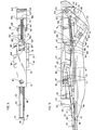
- the Mechanism 27 comprises a block-shaped knife holder 67, a first and a second articulated arm 71 and 73 and a tension spring 75 stretched between the two.
- the knife holder 67 consists of a front Part 77, a rear part 79 and with the rear part 79 structurally connected side parts 81.
- the front part 77 has a recess 83 into which the knife 25 is received, and a threaded bore 85 into which a hexagon socket set screw 87 is rotated lies against the knife 25 and this in the recess holds on.
- FIG. 8 shows grooves 99 on the main housing part 31, in which the side parts 81 of the knife holder 67 sliding are movable.
- the knife holder 67 is thus accommodated in the housing part 31 and can be in Move the longitudinal direction of the housing 23.
- the arm 71 is pivotable attached to the rear part 79 of the knife holder.
- the rear part 79 has two bearing parts 101 and 103 which each have a hole (not shown), through which a bolt 105 is inserted.
- a front one Part 107 of the arm 71 lies between the bearing parts 101 and 103 and also has a (not shown) Bore through which the bolt 105 passes.
- the arm 71 is articulated with its rear part 109 connected to a front part 111 of the arm 73.
- the front part 111 of arm 73 has two bearing parts 113 and 115, each having a bore (not shown) included, through which a bolt 117 is inserted.
- Rear Part of the arm 71 lies between the bearing parts 101 and 103 and also has a (not shown) Bore through which the bolt 117 passes.
- the Arm 73 a rear part 119, which is by means of a bolt 121 pivoted to the housing main part 31 is.
- a bolt 121 pivoted to the housing main part 31
- one is in the main housing part 31
- Recess 123 provided in which the rear part 119 is housed.
- the bolt 121 leads through the Bores 125 and 127 of the housing and a bore 129 in the rear part 119.
- the bolt 121 will by means of an Allen screw 131 in the Bores 125 and 127 of the housing 31 held.
- each arm 71 and 73 has a recess 133 or 135 on their top, whose width is larger than the diameter of the Spring 75.
- Each arm 71 and 73 also has a recess 137 or 139 on the transverse to the recesses 133 and 135 run and between the middle of each Arms and one end 141 and 143 lie.
- the two Arms 71 and 73 also have a longitudinal bar 145 or 147, which runs transversely to the recess and defines openings 149 and 151, respectively.
- the cutting device 11 can be made of hardened Tool steel or other suitable, wear-resistant Be made of materials.
- the device 11 is on the jacketed tendon 16 placed at a freely selectable point, expediently near the anchoring device 20 to achieve that the sheath 14 in immediate Near the area can be removed in which the conical inside 48 of the anchoring device 20 close to the covered tendon 16. With the removal of the sheathing on one such place will ensure that subsequently a (not shown) jig on the exposed tendon can be applied and will also ensure that a sufficient Friction between the exposed The tendon and the anchoring wedges are created between the tendon and the anchoring device 20 can be applied after the prescribed Traction is applied.
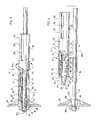
- FIGS. 1 to 4 The operation of the cutting device 11 can will be explained with reference to FIGS. 1 to 4.
- the device 11 to one side of a Tendon 16 brought with the oblique front Part 29 of the device against the anchoring device 20 directed, the opening 57 (see FIG. 7) of the Housing facing the tendon 16.
- the knife 25 is in the withdrawn position Position, the front knife end 95 in the front oblique part 29 of the housing 23 is located.
- the Messerhahe- and -ausfahrmechanik 27 is in one first angled position, the spring 75 being the front End 107 of arm 71 against rear end 119 les Arms 73 pulls.
- the device 11 in the direction of the Tendon 16 moves until the inner surfaces 59 and 63 Read tendon 16 partially, and the area 65 on the casing 14 of the tendon 16 egt.
- the arm 71 touches the Jacket 14, and rear portion 109 of arm 71 is moved towards the spring 75, whereby the front Part 107 of the arm 71 in the longitudinal direction towards the front housing part 29 is moved.
- the spring 75 occurs when the Housing contact surface 65 (see FIG. 9) on the casing 14 butts and the arms 71 and 73 in the longitudinal direction are fully stretched into slots 133 and 135 and the knife holding and extending mechanism 27 is in a second, stretched position. If the mechanics 27 this stretched position has reached, the knife 25 is in an intended Cutting position.
- the knife 89 is located here within slot 35 while top 93 of the knife outside the outer surfaces 37, 39 and 41 of the housing part 29 is and the front end 95 of Knife 25 and the piercing tip 98 from the part 29 beveled at the front against the anchoring arrangement 20 are directed. If the knife 25 of the device 11 is in the cutting position, is the cutting edge 97 near the casing 14 or is against her; however, tip 98 penetrates not yet in the casing 14.
- the device 11 is encased on the Tendon 16 along towards the anchoring device 20 in the direction indicated by arrow 160 in FIG. 2 implied senses pushed up the flat surface 45 of the federal government 43 against the end face 50 of the anchoring device 20 sets, as shown in Fig. 3.
- the front part 29 of the housing 23 in the keying opening 18 occurs through the conical inner surface 48 of the anchoring device 20 is defined, touches the top 93 of the knife 25 the conical Surface 48. This will make the front end 95 of the knife 25 moved in the direction of the casing 14, and pierces the tip 98 at the front knife end 95 the jacket 14 at a preselected location 162 deep inside the wedge opening 18 in the Near the point where the conical surface 48 in the immediate Is near the jacket or touching it.
- the knife tip 98 at this puncture point stands and the cutting edge 97 is thus on the provided cutting point, touch the outside 37 and 41 of the front end piece 29 preferably the conical surface 48 of the entire surface Anchoring device 20 so that device 11 aligned substantially coaxially with the tendon 16 is. This ensures that the cutting edge 97 completely cuts open the casing 14 and the casing 14 is separated from the tendon 16 is when the device 11 around the tendon is rotated.
- the device 11 is now rotated as is indicated by the arrow 164 in Fig. 3, the Cutting edge 97, the sheath 14 along one The circumferential line of the tendon 16 cuts open.
- Some anchoring devices have (not shown) annular sealing element between the tendon 16 and the surface 48 on the Place 162 or near where the face 48 is the tendon 16 reaches.
- An inventive Device 11 can be designed so that the knife cutting edge 97 into a predetermined as needed Puncture / cutting position at a point in the Close to or abutting such a seal brought.
- Tensioning device 16 turns the device into one by one Arrow 166 in the direction indicated in FIG. 4 moves, whereby the knife edge 97 in its original position, lifted off the jacket, return can. Then the device 11 is removed from the tendon 16 removed.
- the spring 75 presses the arm part 107 against the arm part 119, whereby the knife holder 67 backwards towards the rear housing part 33 pushed and the knife 25 in the withdrawn Position is returned.
- the sheath 14 is then removed from the tendon 16 removed by looking in the direction of the arrow 166 in Fig. 4 and pushed over the end of the tendon 16 becomes.
- the cutting device according to the invention and the inventive method is a fast, uncomplicated and effective means of separation a sheathing from a tendon and on a location within the recess of an anchoring device specified. It will be an excellent one Corrosion protection of the tendon achieved because the sheathing the tendon until just before protects the step of tensioning the tendon. After tensioning, the casing can be opened again the tendon be pulled so that corrosion protection continues given is.
- a device according to the invention advantageously works with the existing ones, typically having conical inner walls Anchoring bodies or devices together, by providing a knife that faces the Bends the sheathing and cuts through the sheathing, when the knife touches the inner wall.
- the invention is not limited to use a cutting knife from a wall is deflected to cut open the casing.
- the device can be used with a knife equipment that occupies a fixed position for use in anchoring devices with wide or non-conical locking wedge openings.
- Feed and return mechanics can be dispensed with be.
- the invention therefore does not necessarily have to be be equipped with such a mechanism.
- the invention is based on covered, single-strand tendons for reinforcement of concrete components have been described, however should not be seen as a limitation, because the devices and methods according to the invention can be used to cut jackets single and multi-strand tendons in a variety other applications, including amplification of steel structures, as well as rock and Ground anchors.
Landscapes
- Engineering & Computer Science (AREA)
- Architecture (AREA)
- Mechanical Engineering (AREA)
- Civil Engineering (AREA)
- Structural Engineering (AREA)
- Piles And Underground Anchors (AREA)
Description
- Fig. 1
- zeigt als Seitenriß, teilweise im Schnitt, eine erfindungsgemäße Vorrichtung zum Aufschneiden einer Ummantelung, zusammen mit einem in eine Verankerung eingeführten ummantelten Spannglied;
- Fig. 2
- zeigt als Seitenriß, teilweise im Schnitt, die Vorrichtung nach Fig. 1 in Schneideposition und auf das ummanteite Spannglied aufgesetzt;
- Fig. 3
- ist eine mit Fig. 2 vergleichbare Ansicht der Vorrichtung nach Fig. 1 im Eingriff zum Schneiden;
- Fig. 4
- ist eine mit Fig. 1 vergleichbare Ansicht, nach dem Schneiden.
- Fig. 5
- zeigt in größerem Maßstab als Seitenriß die Messerhalterungs- und -ausfahrmechanik der Vorrichtung nach Fig. 1, wobei zur Verdeutlichung von Einzelheiten einige Teile weggelassen sind;
- Fig. 6
- ist eine Draufsicht auf die Messerhalterungsund -ausfahrmechanik nach Fig. 5 in größerem Maßstab;
- Fig. 7
- zeigt in größerem Maßstab das Ende der Vorrichtung, gesehen aus Richtung der Linie 7-7 in Fig. 1;
- Fig. 8
- zeigt in größerem Maßstab einen Querschnitt durch die Vorrichtung längs der Linie 8-8 in Fig. 1;
- Fig. 9
- zeigt in größerem Maßstab einen Querschnitt durch die Vorrichtung längs der Linie 9-9 in Fig. 1 und
- Fig. 10
- zeigt in größerem Maßstab einen Querschnitt durch die Vorrichtung längs der Linie 10-10 in Fig. 1.
Claims (10)
- Vorrichtung zum Aufschneiden einer ein Spannglied (16) umgebenden Ummantelung (14) aus Kunststoff, insbesondere PE, gekennzeichnet durch1. ein auf einem Abschnitt des Spannglieds drehbar anbringbares Gehäuse (23), in dem ein Messer (25) mit einer Schneidkante (97) und eine Halte- und Betätigungsvorrichtung (27) für das Messer angeordnet sind,2. wobei das Gehäuse (23) einen vorderen Teil (29) mit konischer Außenfläche aufweist, derwenn das von der Ummantelung (14) umgebene Spannglied (16) in eine Verankerungsvorrichtung (20) eingeführt und die Vorrichtung (11) auf dem Spannglied (16) angebracht ist,in eine Ausnehmung (18) einer Verankerungsvorrichtung (20) einführbar ist unddurch Anlage an der Innenfläche (48) der Ausnehmung (18) eine koaxiale Ausrichtung des Gehäuses (23) und des Spannglieds (16) bewirkt, und daß3. die Schneidkante (97) des Messers (25) durch Anlage des Messerrückens (93) an der Innenfläche (48) der Ausnehmung (18) in Kontakt mit der Ummantelung (14) gerät,4. wodurch die Ummantelung (14) an einer ausgewählten Stelle innerhalb der Verankerungsvorrichtung (20) aufgeschnitten wird, wenn die Vorrichtung (11) um das Spannglied (16) gedreht wird.
- Vorrichtung nach Anspruch 1, dadurch gekennzeichnet, daß das Gehäuse (23) eine eine Öffnung (57) definierende Innenfläche (59, 63) aufweist, die das ummantelte Spannglied (16) teilweise umgibt, wenn die Vorrichtung (11) darauf angebracht ist.
- Vorrichtung nach Anspruch 1 oder 2, dadurch gekennzeichnet, daß das Gehäuse (23) einen an den vorderen konischen Teil (29) anschließenden, im wesentlichen zylindrischen Teil (31) umfaßt, in dem die Halte- und Betätigungsvorrichtung (27) für das Messer (25) angeordnet ist.
- Vorrichtung nach einem der Ansprüche 1 bis 3, dadurch gekennzeichnet, daß die Halte- und Betätigungsvorrichtung (27) für das Messer (25) Mittel zum Halten und Ausfahren des Messers in eine erste und eine zweite Position umfaßt, wobei, wenn die Halterung in der ersten Position steht, die Schneidkante (97) des Messers (25) sich innerhalb des Gehäuses (23) befindet und, wenn die Halterung in der zweiten Position steht, die Schneidkante (97) des Messers (25) aus dem Gehäuse (23) in eine gewählte Schneidstellung hinausragt.
- Vorrichtung nach Anspruch 4, dadurch gekennzeichnet, daß der vordere konische Teil (29) des Gehäuses (23) einen Schlitz (35) aufweist, aus dem das Messer (25) hinausragt, wenn die Mittel in der zweiten Position stehen.
- Vorrichtung nach Anspruch 4 oder 5, dadurch gekennzeichnet, daß die Mittel in der zweiten Position stehen, wenn die Vorrichtung (11) auf dem ummantelten Spannglied (16) angebracht ist und daß die Mittel selbsttätig von der zweiten Position in die erste Position übergehen, wenn die Vorrichtung (11) von dem Spannglied (16) abgenommen wird.
- Vorrichtung nach einem der Ansprüche 4 bis 6, dadurch gekennzeichnet, daß die Mittel zum Halten und Ausfahren des Messers (25) einen ersten und einen zweiten Arm (71 bzw. 73) aufweisen, die durch eine Zugfeder (75) miteinander verbunden sind, wobei die Zugfeder den ersten Arm (71) in Richtung auf den zweiten Arm (73) zieht, daß der erste Arm (71) gelenkig an dem Gehäuse (29) und der zweite Arm (73) gelenkig an dem ersten Arm (71) und gelenkig an einer Halterung (67) für das Messer (25) angebracht ist, die an dem Gehäuse (23) gleitend verschiebbar ist.
- Vorrichtung nach Anspruch 7, dadurch gekennzeichnet, daß das Messer (25) an der Messerhalterung (67) lösbar befestigt ist.
- Vorrichtung nach Anspruch 7, dadurch gekennzeichnet, daß der erste und/oder der zweite Arm (71 bzw. 73) sich gegen das ummantelte Spannglied (16) legen, die Zugfeder (75) dehnen und das Messer (25) in die Schneidposition verlagern, wenn die Mittel zum Halten und Ausfahren des Messers sich in der zweiten Position befinden.
- Vorrichtung nach Anspruch 7, dadurch gekennzeichnet, daß die Messerhalterung (67) seitliche Vorsprünge (81) und das Gehäuse seitliche Nuten (99) aufweisen, in denen die Vorsprünge (81) gleitend verschiebbar sind.
Applications Claiming Priority (2)
| Application Number | Priority Date | Filing Date | Title |
|---|---|---|---|
| US34904594A | 1994-12-02 | 1994-12-02 | |
| US349045 | 1994-12-02 |
Publications (2)
| Publication Number | Publication Date |
|---|---|
| EP0715040A1 EP0715040A1 (de) | 1996-06-05 |
| EP0715040B1 true EP0715040B1 (de) | 1998-09-23 |
Family
ID=23370683
Family Applications (1)
| Application Number | Title | Priority Date | Filing Date |
|---|---|---|---|
| EP95118731A Expired - Lifetime EP0715040B1 (de) | 1994-12-02 | 1995-11-29 | Vorrichtung zum Aufschneiden von Ummantelungen |
Country Status (5)
| Country | Link |
|---|---|
| US (1) | US5745996A (de) |
| EP (1) | EP0715040B1 (de) |
| CA (1) | CA2163063C (de) |
| DE (1) | DE59503688D1 (de) |
| MX (1) | MX9504747A (de) |
Families Citing this family (10)
| Publication number | Priority date | Publication date | Assignee | Title |
|---|---|---|---|---|
| DE19733822A1 (de) * | 1997-08-05 | 1999-02-11 | Dyckerhoff & Widmann Ag | Verfahren zum Einbauen und Spannen eines freigespannten Zugglieds und Vorrichtung zum Durchführen des Verfahrens |
| US6311600B1 (en) * | 1999-10-20 | 2001-11-06 | Hong Kong Polytechnic University | Electric power cable sheath cutter |
| US6739229B2 (en) | 2002-06-19 | 2004-05-25 | Thomas D. Scollon | Cable stripping device |
| JP2005218212A (ja) * | 2004-01-29 | 2005-08-11 | Yazaki Corp | 編組の切断装置 |
| US7243429B2 (en) * | 2005-03-23 | 2007-07-17 | Landes Mark J | Wire stripper systems |
| US7316058B2 (en) * | 2005-08-15 | 2008-01-08 | Beam-Chi Jee | Coaxial cable stripper |
| US8443520B2 (en) * | 2008-09-09 | 2013-05-21 | Kyle Viereck | Device for stripping sheathing on unbonded post-tensioning tendons |
| US9615823B2 (en) | 2011-01-27 | 2017-04-11 | Medtronic, Inc. | Tools and methods for removing anchors from medical leads |
| US9517332B2 (en) | 2011-01-27 | 2016-12-13 | Medtronic, Inc. | Anchors including rigid bodies defining full length slots for use with implantable medical leads |
| CN117731105A (zh) * | 2022-09-21 | 2024-03-22 | 卡特里·帕利亚罗 | 美妆笔削笔刀 |
Family Cites Families (38)
| Publication number | Priority date | Publication date | Assignee | Title |
|---|---|---|---|---|
| US2735320A (en) * | 1956-02-21 | green | ||
| US853969A (en) * | 1906-11-05 | 1907-05-21 | John A Goebler | Bottle-wire cutter. |
| US1841251A (en) * | 1926-03-20 | 1932-01-12 | Kenneth W Miller | Cable tool |
| US1801706A (en) * | 1929-07-24 | 1931-04-21 | Loy W Westfall | Slitting tool |
| US2120398A (en) * | 1937-01-16 | 1938-06-14 | Bell Telephone Labor Inc | Cable stripping tool |
| US2187215A (en) * | 1938-05-16 | 1940-01-16 | Lemuel J Wood | Electrical insulation cutter |
| US2385368A (en) * | 1942-06-01 | 1945-09-25 | Henrietta G Montgomery | Cable slitter |
| US2525097A (en) * | 1945-06-28 | 1950-10-10 | Duplan Corp | Rotary knife for cutting yarn on quills |
| US2695537A (en) * | 1952-04-08 | 1954-11-30 | William D Imman | Coaxial cable stripper |
| US2787177A (en) * | 1955-05-05 | 1957-04-02 | William L Frye | Wire stripping tool |
| US3161088A (en) * | 1962-12-04 | 1964-12-15 | Harold J Tolman | Stripper for coaxial cables |
| US3535785A (en) * | 1968-02-26 | 1970-10-27 | James J Matthews | Cable scoring tool |
| DE1930479C3 (de) * | 1969-06-16 | 1975-04-24 | Standard Elektrik Lorenz Ag, 7000 Stuttgart | Abisolier- und Wickelpistole |
| US3851687A (en) * | 1973-10-15 | 1974-12-03 | M Jones | Pencil sharpener |
| US4117749A (en) * | 1976-08-09 | 1978-10-03 | The United States Of America As Represented By The Administrator Of The National Aeronautics And Space Administration | Wire stripper |
| FR2493619A2 (fr) * | 1977-05-27 | 1982-05-07 | Sibille & Cie Ateliers | Couteau de securite pour denuder les cables electriques |
| US4116092A (en) * | 1977-06-13 | 1978-09-26 | Ashtabula Development Co. | Device for stripping insulation from a wire |
| US4227431A (en) * | 1979-02-08 | 1980-10-14 | Martin Marietta Corporation | Axial tube cutter for severing electrical connector coupling rings |
| US4368654A (en) * | 1981-02-23 | 1983-01-18 | O. K. Machine And Tool Corp. | Adjustable stripping tool |
| US4426778A (en) * | 1981-12-14 | 1984-01-24 | Avco Corporation | Device for stripping wire and cable |
| AT382984B (de) * | 1982-06-14 | 1987-05-11 | Krampe Josef | Abisoliergeraet zur entfernung der aeusseren isolierung ein- oder mehradriger kabel |
| US4509257A (en) * | 1982-06-18 | 1985-04-09 | Takashi Moriyama | Method of and apparatus for baring the end of sheathed multicore cable |
| US4447949A (en) * | 1982-09-30 | 1984-05-15 | Kane Michael W | Wire stripper |
| US4543717A (en) * | 1983-12-16 | 1985-10-01 | Tektronix, Inc. | Cable stripper |
| EP0146397A3 (en) * | 1983-12-20 | 1987-04-29 | Vasilije Kokotovich | Wire stripper |
| US4557163A (en) * | 1984-07-11 | 1985-12-10 | The Boeing Company | Shield stripper for electrical wiring |
| US4688707A (en) * | 1985-09-17 | 1987-08-25 | Thomas & Betts Corporation | Method and apparatus for cleaving optical fiber |
| US4741104A (en) * | 1987-03-12 | 1988-05-03 | Northern Telecom Limited | Cutting tool for tubes |
| US4918887A (en) * | 1987-10-14 | 1990-04-24 | Vsl Corporation | Protective tendon tensioning anchor assemblies |
| US4839986A (en) * | 1988-03-18 | 1989-06-20 | Grantham Debs E | Grafting apparatus |
| US4858315A (en) * | 1988-05-09 | 1989-08-22 | N. J. Wheeler | Shield stripping apparatus for electrical cable |
| DE3904323A1 (de) * | 1989-02-14 | 1990-08-16 | P W Weidling & Sohn Gmbh & Co | Geraet zur entfernung der aeusseren isolierung von mehradrigen kabeln |
| US5074043A (en) * | 1990-11-26 | 1991-12-24 | Mills Edward O | Safety-cable jacket remover |
| CH683655A5 (de) * | 1991-11-12 | 1994-04-15 | Jiri Stepan | Verfahren und Vorrichtung zum Durchtrennen einer Kabelummantelung aus Fasern. |
| US5263291A (en) * | 1992-11-02 | 1993-11-23 | Knight David W | Method and apparatus for corrosion protection of the terminal end of a post-tensioned tendon |
| GB9305535D0 (en) * | 1993-03-17 | 1993-05-05 | Charest Michel | Device for sectionning carboard tubes |
| US5347777A (en) * | 1993-04-23 | 1994-09-20 | Post Tension Product Mfg., Inc. | Anchor plate assembly |
| US5632088A (en) * | 1995-05-25 | 1997-05-27 | Naso; Dan | Cable stripper device |
-
1995
- 1995-11-13 MX MX9504747A patent/MX9504747A/es unknown
- 1995-11-16 CA CA002163063A patent/CA2163063C/en not_active Expired - Fee Related
- 1995-11-29 EP EP95118731A patent/EP0715040B1/de not_active Expired - Lifetime
- 1995-11-29 DE DE59503688T patent/DE59503688D1/de not_active Expired - Fee Related
-
1996
- 1996-04-17 US US08/635,037 patent/US5745996A/en not_active Expired - Fee Related
Also Published As
| Publication number | Publication date |
|---|---|
| MX9504747A (es) | 1997-05-31 |
| CA2163063C (en) | 1998-08-11 |
| EP0715040A1 (de) | 1996-06-05 |
| US5745996A (en) | 1998-05-05 |
| DE59503688D1 (de) | 1998-10-29 |
| CA2163063A1 (en) | 1996-06-03 |
Similar Documents
| Publication | Publication Date | Title |
|---|---|---|
| DE2627524C3 (de) | Verpreßanker | |
| DE2642008A1 (de) | Geraet zum abstreifen der verkleidung von arbeitsgegenstaenden | |
| EP0896108B1 (de) | Verfahren zum Einbauen und Spannen eines freigespannten Zugglieds und Vorrichtung zum Durchführen des Verfahrens | |
| DE10062227A1 (de) | Verfahren zum Einbauen und Spannen eines freigespannten Zugglieds, insbesondere eines Schrägseils für eine Schrägseilbrücke sowie Verankerungsvorrichtung zum Durchführen des Verfahrens | |
| EP0715040A1 (de) | Vorrichtung zum Aufschneiden von Ummantelungen | |
| EP3128110A1 (de) | Sicherheitsscharnier | |
| DE29506476U1 (de) | Vorrichtung zur Verwendung beim Einführen der einzelnen Zugelemente eines frei gespannten Zugglieds | |
| DE2637350A1 (de) | Spreizduebel | |
| DE2611677B2 (de) | Vorrichtung zum Einbringen von Rohren | |
| EP0004374A1 (de) | Vorrichtung zum Verbinden von zwei Profilstäben | |
| EP0504587A2 (de) | Vorrichtung zur Befestigung eines Sanitärkörpers | |
| DE19604243C2 (de) | Beschlag zum Verbinden von Bauteilen | |
| EP0622575A2 (de) | Halterung mit einer Rohrschelle oder dergleichen | |
| EP2839911B1 (de) | Schneidwerkzeug | |
| DE3615163C2 (de) | ||
| DE3211580A1 (de) | Vorrichtung zum mechanischen sprengen von gestein | |
| DE68901809T2 (de) | Einsatz fuer u-profile. | |
| DE19527138C1 (de) | Vorrichtung zum Ersetzen einer alten Versorgungsleitung durch eine neue Leitung | |
| EP0996797A1 (de) | Bauteil | |
| AT512411B1 (de) | Ortbetonschutzwand | |
| DE3504942C2 (de) | ||
| DE3309055A1 (de) | Verriegelungssystem | |
| DE3512065C1 (de) | Vorrichtung zum Entfernen eines Abschnittes einer Ummantelung von im wesentlichen stangenförmigen Gegenständen, insbesondere elektrischen Kabeln | |
| DE7317150U (de) | Verankerung fuer seile o.dgl., insbesondere fuer die spannglieder im spannbeton-bau | |
| DE29708469U1 (de) | Transportelement |
Legal Events
| Date | Code | Title | Description |
|---|---|---|---|
| PUAI | Public reference made under article 153(3) epc to a published international application that has entered the european phase |
Free format text: ORIGINAL CODE: 0009012 |
|
| 17P | Request for examination filed |
Effective date: 19960411 |
|
| AK | Designated contracting states |
Kind code of ref document: A1 Designated state(s): BE DE FR NL |
|
| 17Q | First examination report despatched |
Effective date: 19970321 |
|
| GRAG | Despatch of communication of intention to grant |
Free format text: ORIGINAL CODE: EPIDOS AGRA |
|
| GRAG | Despatch of communication of intention to grant |
Free format text: ORIGINAL CODE: EPIDOS AGRA |
|
| GRAH | Despatch of communication of intention to grant a patent |
Free format text: ORIGINAL CODE: EPIDOS IGRA |
|
| GRAH | Despatch of communication of intention to grant a patent |
Free format text: ORIGINAL CODE: EPIDOS IGRA |
|
| GRAA | (expected) grant |
Free format text: ORIGINAL CODE: 0009210 |
|
| AK | Designated contracting states |
Kind code of ref document: B1 Designated state(s): BE DE FR NL |
|
| RIN1 | Information on inventor provided before grant (corrected) |
Inventor name: KAST, GERHARD G. Inventor name: SINGER, DONALD J. Inventor name: KENNY, DANIEL P. |
|
| REF | Corresponds to: |
Ref document number: 59503688 Country of ref document: DE Date of ref document: 19981029 |
|
| ET | Fr: translation filed | ||
| PLBE | No opposition filed within time limit |
Free format text: ORIGINAL CODE: 0009261 |
|
| STAA | Information on the status of an ep patent application or granted ep patent |
Free format text: STATUS: NO OPPOSITION FILED WITHIN TIME LIMIT |
|
| 26N | No opposition filed | ||
| BECA | Be: change of holder's address |
Owner name: *DYWIDAG-SYSTEMS INTERNATIONAL G.M.B.H.DYWIDAGSTRA Effective date: 20030423 |
|
| BECH | Be: change of holder |
Owner name: *DYWIDAG-SYSTEMS INTERNATIONAL G.M.B.H. Effective date: 20030423 |
|
| NLS | Nl: assignments of ep-patents |
Owner name: WALTER BAU-AKTIENGESELLSCHAFT Owner name: DYWIDAG-SYSTEMS INTERNATIONAL GMBH |
|
| REG | Reference to a national code |
Ref country code: FR Ref legal event code: TP |
|
| REG | Reference to a national code |
Ref country code: FR Ref legal event code: TP |
|
| PGFP | Annual fee paid to national office [announced via postgrant information from national office to epo] |
Ref country code: NL Payment date: 20041117 Year of fee payment: 10 |
|
| PGFP | Annual fee paid to national office [announced via postgrant information from national office to epo] |
Ref country code: FR Payment date: 20041118 Year of fee payment: 10 |
|
| PGFP | Annual fee paid to national office [announced via postgrant information from national office to epo] |
Ref country code: BE Payment date: 20041124 Year of fee payment: 10 |
|
| PGFP | Annual fee paid to national office [announced via postgrant information from national office to epo] |
Ref country code: DE Payment date: 20041125 Year of fee payment: 10 |
|
| PG25 | Lapsed in a contracting state [announced via postgrant information from national office to epo] |
Ref country code: BE Free format text: LAPSE BECAUSE OF NON-PAYMENT OF DUE FEES Effective date: 20051130 |
|
| PG25 | Lapsed in a contracting state [announced via postgrant information from national office to epo] |
Ref country code: NL Free format text: LAPSE BECAUSE OF NON-PAYMENT OF DUE FEES Effective date: 20060601 Ref country code: DE Free format text: LAPSE BECAUSE OF NON-PAYMENT OF DUE FEES Effective date: 20060601 |
|
| PG25 | Lapsed in a contracting state [announced via postgrant information from national office to epo] |
Ref country code: FR Free format text: LAPSE BECAUSE OF NON-PAYMENT OF DUE FEES Effective date: 20060731 |
|
| NLV4 | Nl: lapsed or anulled due to non-payment of the annual fee |
Effective date: 20060601 |
|
| REG | Reference to a national code |
Ref country code: FR Ref legal event code: ST Effective date: 20060731 |
|
| BERE | Be: lapsed |
Owner name: *DYWIDAG-SYSTEMS INTERNATIONAL G.M.B.H. Effective date: 20051130 |