EP0714728A1 - Führungs- und Verlegungsvorrichtung für wenigstens zwei vorher angedockten Blechzuschnitten, insbesondere in einer Schweissanlage - Google Patents
Führungs- und Verlegungsvorrichtung für wenigstens zwei vorher angedockten Blechzuschnitten, insbesondere in einer Schweissanlage Download PDFInfo
- Publication number
- EP0714728A1 EP0714728A1 EP95402309A EP95402309A EP0714728A1 EP 0714728 A1 EP0714728 A1 EP 0714728A1 EP 95402309 A EP95402309 A EP 95402309A EP 95402309 A EP95402309 A EP 95402309A EP 0714728 A1 EP0714728 A1 EP 0714728A1
- Authority
- EP
- European Patent Office
- Prior art keywords
- carriages
- carriage
- sheet blanks
- blanks
- shoe
- Prior art date
- Legal status (The legal status is an assumption and is not a legal conclusion. Google has not performed a legal analysis and makes no representation as to the accuracy of the status listed.)
- Granted
Links
- 238000003466 welding Methods 0.000 title claims abstract description 19
- 238000009434 installation Methods 0.000 title claims abstract description 7
- 239000002184 metal Substances 0.000 title claims description 22
- 238000006073 displacement reaction Methods 0.000 claims abstract description 8
- 238000005096 rolling process Methods 0.000 claims abstract description 4
- 230000000712 assembly Effects 0.000 claims abstract description 3
- 238000000429 assembly Methods 0.000 claims abstract description 3
- 239000000463 material Substances 0.000 claims description 6
- 230000000295 complement effect Effects 0.000 claims description 5
- 229920000642 polymer Polymers 0.000 claims description 4
- 239000012530 fluid Substances 0.000 claims description 3
- 229910000831 Steel Inorganic materials 0.000 description 2
- 239000010959 steel Substances 0.000 description 2
- 230000006866 deterioration Effects 0.000 description 1
- 238000004519 manufacturing process Methods 0.000 description 1
- 238000003032 molecular docking Methods 0.000 description 1
Images


Classifications
-
- B—PERFORMING OPERATIONS; TRANSPORTING
- B23—MACHINE TOOLS; METAL-WORKING NOT OTHERWISE PROVIDED FOR
- B23K—SOLDERING OR UNSOLDERING; WELDING; CLADDING OR PLATING BY SOLDERING OR WELDING; CUTTING BY APPLYING HEAT LOCALLY, e.g. FLAME CUTTING; WORKING BY LASER BEAM
- B23K37/00—Auxiliary devices or processes, not specially adapted for a procedure covered by only one of the other main groups of this subclass
- B23K37/04—Auxiliary devices or processes, not specially adapted for a procedure covered by only one of the other main groups of this subclass for holding or positioning work
- B23K37/0408—Auxiliary devices or processes, not specially adapted for a procedure covered by only one of the other main groups of this subclass for holding or positioning work for planar work
-
- B—PERFORMING OPERATIONS; TRANSPORTING
- B23—MACHINE TOOLS; METAL-WORKING NOT OTHERWISE PROVIDED FOR
- B23K—SOLDERING OR UNSOLDERING; WELDING; CLADDING OR PLATING BY SOLDERING OR WELDING; CUTTING BY APPLYING HEAT LOCALLY, e.g. FLAME CUTTING; WORKING BY LASER BEAM
- B23K26/00—Working by laser beam, e.g. welding, cutting or boring
- B23K26/08—Devices involving relative movement between laser beam and workpiece
- B23K26/083—Devices involving movement of the workpiece in at least one axial direction
- B23K26/0838—Devices involving movement of the workpiece in at least one axial direction by using an endless conveyor belt
-
- B—PERFORMING OPERATIONS; TRANSPORTING
- B23—MACHINE TOOLS; METAL-WORKING NOT OTHERWISE PROVIDED FOR
- B23K—SOLDERING OR UNSOLDERING; WELDING; CLADDING OR PLATING BY SOLDERING OR WELDING; CUTTING BY APPLYING HEAT LOCALLY, e.g. FLAME CUTTING; WORKING BY LASER BEAM
- B23K26/00—Working by laser beam, e.g. welding, cutting or boring
- B23K26/20—Bonding
- B23K26/21—Bonding by welding
- B23K26/24—Seam welding
- B23K26/244—Overlap seam welding
-
- B—PERFORMING OPERATIONS; TRANSPORTING
- B23—MACHINE TOOLS; METAL-WORKING NOT OTHERWISE PROVIDED FOR
- B23K—SOLDERING OR UNSOLDERING; WELDING; CLADDING OR PLATING BY SOLDERING OR WELDING; CUTTING BY APPLYING HEAT LOCALLY, e.g. FLAME CUTTING; WORKING BY LASER BEAM
- B23K26/00—Working by laser beam, e.g. welding, cutting or boring
- B23K26/20—Bonding
- B23K26/21—Bonding by welding
- B23K26/24—Seam welding
- B23K26/26—Seam welding of rectilinear seams
-
- B—PERFORMING OPERATIONS; TRANSPORTING
- B23—MACHINE TOOLS; METAL-WORKING NOT OTHERWISE PROVIDED FOR
- B23K—SOLDERING OR UNSOLDERING; WELDING; CLADDING OR PLATING BY SOLDERING OR WELDING; CUTTING BY APPLYING HEAT LOCALLY, e.g. FLAME CUTTING; WORKING BY LASER BEAM
- B23K2101/00—Articles made by soldering, welding or cutting
- B23K2101/18—Sheet panels
Definitions
- the present invention relates to a device for guiding at least two sheet metal blanks previously approached edge to edge, in particular for a continuous welding installation by means of a high energy density beam.
- the welding by means of a high energy density beam, such as for example a laser beam, of two sheet metal blanks has found an important industrial outlet, in particular in the production of butted and welded parts for example for the automobile industry.
- the sheet blanks can be of different geometric shapes and / or of different thicknesses, or even have different grades of steel.
- these welding installations comprise a lateral positioning zone for one of the sheet blanks not relative to the axis of the beam, then a docking zone for the two sheet blanks edge to edge and finally a entrainment area of these blanks below the high energy density beam while keeping the two sheet blanks side by side.
- this type of holding device does not allow sheet metal blanks of different geometric shapes to be welded together.
- a holding device which comprises pairs of pallets, one next to the other each carrying at least one sheet blank.
- the sheet blanks are fixed for example by clamping on the pallets.
- This device also includes, at the welding zone, inclined pressure rollers to hold the sheet blanks from above.
- This device has a drawback which mainly lies in the fact that it does not make it possible to minimize the clearance between the edges to be welded of the two sheet blanks so that at the time of welding, the clearance increases due to the thermal expansion of the welded area thus causing poor quality welds.
- the object of the invention is to avoid these drawbacks by proposing a device for guiding and transferring at least two sheet blanks previously approached edge to edge which makes it possible to control the clearance between the edges to be welded of the two sheet blanks to the during their movement during the entire welding operation.
- the invention therefore relates to a device for guiding and transferring at least two sheet blanks previously approached edge to edge to form a joint plane, in particular in a continuous welding installation by means of a high beam.
- energy density of the type comprising two sets of support and transfer of the sheet blanks in the direction of the high energy density beam, each arranged on either side of the joint plane and movable in synchronization, one with the other, characterized in that each support and transfer assembly comprises at least one lower series of carriages articulated together in a vertical plane and movable parallel to the joint plane on a raceway forming a horizontal reference plane, the carriages of said lower series each supporting at least a shoe movable relative to said carriages perpendicular to the joint plane and constituting a substantially continuous contact surface with the underside of the sheet blanks or at least one upper series of carriages articulated together in a vertical plane, arranged facing said series lower of carriages and movable parallel to the joint plane on a raceway, the carriages of said upper series each supporting at least one shoe
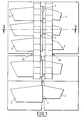
- the device shown schematically in FIG. 1 is intended for guiding and transferring several pairs of sheet blanks 2 and 3 in a continuous edge-to-edge welding installation of said sheet blanks 2 and 3 by means of a high energy density beam 1, as for example a laser beam.
- a high energy density beam 1 as for example a laser beam.
- the sheet blanks 2 and 3 may be of different geometric shapes and / or of different thicknesses, or even have different grades of steel, and are intended, for example, for the automotive industry or for industries using semi-finished parts.
- the two sheet blanks 2 and 3 of each pair are approached edge to edge to form a joint plane 4 and travel continuously below the high energy density beam 1 for their welding.
- the positioning of the sheet blanks 2 and 3 must satisfy, in the weld zone, several requirements which are in particular the relative position of the edges to be welded relative to the axis of the beam to be high energy density 1 and the relative pressure on these edges in order to control and reduce the clearance between said edges during the movement of the sheet blanks 2 and 3.
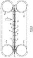
- the device shown in Figs. 1 to 4 includes two sets 20 and 60 of support and transferring the sheet blanks 2 and 3 in the direction of the high energy density beam 1, each arranged on either side of the joint plane 4 and displaceable in synchronization with one another.
- the assembly 20 for supporting and transferring the sheet blanks 2 comprises a lower series 21 of carriages 22 hinged together in a vertical plane and movable parallel to the joint plane 4 of the sheet blanks 2 and 3 on a raceway 23 forming a horizontal reference plane.
- the carriages 22 of the lower series 21 each support at least one shoe 24 movable relative to said carriages 22 perpendicular to the joint plane 4 and constituting a substantially continuous contact surface with the underside of the blanks sheet metal 2.
- the assembly 20 for supporting and transferring the sheet blanks 2 also comprises an upper series 41 of carriages 42 hinged together in a vertical plane, arranged facing the lower series and movable parallel to the joint plane 4 on a path of bearing 43.
- the carriages 42 of the upper series 41 each support at least one shoe 44 movable relative to said carriages 42 perpendicular to the joint plane 4 of the sheet blanks 2 and 3 and constituting a substantially continuous contact surface with the upper surface of the sheet blanks 2.
- the pads 24 of the lower series 21 of carriages 22 cooperate with means 5 for lateral pressure of the edges to be welded sheet metal blanks 2 and 3 by displacement of the pads 24 perpendicular to the joint plane 4 of said sheet blanks 2 and 3 .
- each carriage 22 comprises at one of its ends, such as for example its front end relative to the direction of movement of the carriages 22, a tenon 25.
- each carriage 22 has, at its rear end, a mortise 26 intended to receive the stud 25 of the adjacent carriage.
- the carriages 22 are hinged together in a vertical plane by means of an axis 27 passing through the mortise 26 and the tenon 25 of two adjacent carriages 22.
- Each carriage 22 also comprises at least two rollers 28 with a horizontal axis, each arranged on one side of the carriage 22 and intended to cooperate with the raceway 23 for guiding the carriages 22.
- each carriage 22 has four rollers 28, two on one side of the carriage 22 and two on the other side of said carriage.
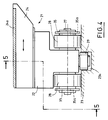
- each carriage 22 comprises at least one roller 29 with a vertical axis intended to cooperate with a groove 23a (FIG. 4) formed in the raceway 23.
- the groove 23a forms a reference axis parallel to the joint plane 4 of the sheet blanks 2 and 3.
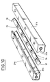
- the pads 24 are independent of each other and each pad 24 is mounted movable perpendicularly to the joint plane 4 on the corresponding carriage 22 by means of two running rails 30 (Fig. 5) each arranged on either side of the longitudinal axis of said shoe 24 and perpendicular to the joint plane 4 of the sheet blanks 2 and 3.
- each running rail 30 is formed by two rods 31a and 31b attached, of rectangular section and provided on their faces opposite a V-shaped groove 32a and 32b with a horizontal axis.
- the running rail 30 also includes a strip 33 of square section, arranged between the strips 31a and 31b at the grooves 32a and 32b.
- This strip 33 comprises cylindrical rollers 34 which project alternately on each of the faces of said strip 33 so that the two rods 31a and 31b slide relative to each other.
- One of the two rods such as for example the rod 31a
- the other of said rods such as for example the rod 31b
- the corresponding pad 24 which allows the displacement of said pad 24 perpendicular to the plane joint 4 of the sheet metal blanks 2 and 3 and prevents any displacement of this shoe 24 relative to the carriage 22 in a direction parallel to said joint plane 4.
- each shoe 24 has a return spring 38 disposed in a recess 39 formed in the upper face of the corresponding carriage 22 in contact with said shoe 24.
- a first end 38a of the return spring 38 is connected to the carriage 22 and a second end 38b of this return spring is connected to a vertical tab 40 secured to the corresponding shoe 24.
- This return spring 38 has the function of returning the corresponding shoe 24 to its initial position after the lateral pressure of the edges to be welded of the sheet blanks 2 and 3.
- the carriages 22 of the series 21 form a loop (Fig. 2) in a vertical plane and comprises drive means with, on the one hand, a first pair of parallel toothed wheels 37a, arranged at a end of the loop, and secondly, a second pair of parallel toothed wheels 37b, disposed at the other end of said loop.
- the means for engaging the carriages 22 are formed by vertical plates 35 fixed to each end of the axes 27 and on either side of the carriages 22. These vertical plates 35 are uniformly distributed over the entire length of the loop formed by the carriages 22 and each have a notch 35a of complementary shape to the teeth of the toothed wheels 37a and 37b.
- the notches 35a cooperate with the teeth toothed wheels 37a and 37b for driving the carriages 22 and the driving in rotation of the toothed wheels 37a and 37b is carried out for example by a geared motor system, not shown, driving one of the pairs of toothed wheels 37a and 37b.
- the carriages 42 are hinged together in a vertical plane by means of an axis passing through the mortise and the tenon of two adjacent carriages 42.
- Each carriage 42 also comprises at least two rollers 28 with a horizontal axis, each arranged on one side of the carriage 42 and intended to cooperate with a raceway 43 for guiding the carriages 42.
- each carriage 42 has four rollers 28, two on one side of the carriage 42 and two on the other side of said carriage.
- each carriage 42 comprises at least one roller 29 with a vertical axis intended to cooperate with a groove 43a (Figs. 3 and 7) formed in the raceway 43.
- the groove 43a also forms a reference axis parallel to the joint plane 4 of the sheet blanks 2 and 3.
- the pads 44 are independent of each other and each pad 44 is mounted movable perpendicular to the joint plane 4 on the corresponding carriage 42 by means of two running rails 30 (Figs. 7 and 8) each arranged on the side and d other from the longitudinal axis of said shoe 44 and perpendicular to the joint plane 4 of the sheet blanks 2 and 3.
- Running rails 30 are identical to those described above for the carriages 22 and the pads 24.
- One of the two rods such as for example the rod 31a of the running rails 30, is integral with the carriage 42 and the other of said rods, such as for example the rod 31b, is integral with the corresponding pad 44 which authorizes the movement of said pad 44 perpendicular to the joint plane 4 of the sheet blanks 2 and 3 and prevents any displacement of this pad 44 relative to the carriage 42 in a direction parallel to said joint plane 4.
- the carriages 42 of the upper series 41 form a loop (FIG. 2) in a vertical block and comprise engagement means with, on the one hand, a first pair of parallel toothed wheels 47a, disposed at one end of the loop and, on the other hand, a second pair of parallel toothed wheels 47b, disposed at the other end of said loop.
- the means for engaging the carriages 42 are identical to the means for engaging the carriages 22 of the lower series 21 and are formed by vertical plates 45 fixed to each end of the axes 27 and on either side of the carts 42.
- These vertical plates 45 are uniformly distributed over the entire length of the loop formed by the carriages 42 and each has notches 45a of complementary shape to the teeth of the toothed wheels 47a and 47b.
- the notches 45a cooperate with the teeth of the toothed wheels 47a and 47b for driving the carriages 42 and the rotational driving of the toothed wheels 47a and 47b is carried out for example by a geared motor system, not shown, causing one pairs of toothed wheels 47a and 47b.
- the pads 44 of the upper series 41 are also provided with return springs in the initial position.
- the assembly 20 for supporting and transferring the sheet blanks 2 cooperates with means 100 for clamping the sheet blanks 2 under vertical force.
- the clamping means 100 at each pad 44 are formed by a jack comprising a body 101 and a piston 102 mounted to slide in the body 101.
- the body 101 and the piston 102 provide an internal chamber 103 containing an incompressible fluid and said piston 102 is returned to the high position by a spring 104 interposed between this piston 102 and the bottom of the chamber 103.
- the piston 102 has at its upper part a roller 105 mounted to rotate freely on a horizontal axis 106 and intended to cooperate with a rolling track 107, as will be seen later.
- the shoe 44 is supported by the carriage 42 at by means of a base 108 and running rails 30 interposed between said carriage 42 and said base 108.
- the shoe 44 is movable, relative to the corresponding carriage 42, on the one hand, in a direction perpendicular to the joint plane 4 of the sheet blanks 2 and 3, by virtue of the running rails 30 and, on the other hand, in a direction perpendicular to the sheet blanks 2.
- the underside of the base 108 comprises a vertical piston 109 intended to penetrate a blind hole 110 formed in the shoe 44.
- the lower surface of the vertical piston 109 provides, with the bottom of the blind hole 110, a chamber 111 connected to the internal chamber 103 by a first conduit 112 disposed in the base 108 and by a second conduit 113 passing through the vertical piston 109.
- the shoe 44 is mounted to slide relative to the base 108 on four vertical rods 114.
- the upper ends of the rods 114 are fixed in the base 112 and the lower ends of these rods are each housed in a recess 115 formed in the shoe 44 and comprises a nut 116.
- a spring 117 is disposed on each rod 114 above the nut 116 in the recess 115 to hold the shoe 44 pressed against the base 112.
- Each shoe 24 and 44 has, on its face in contact with the sheet blanks 2, a layer, respectively 24a and 44a (Figs. 3, 4 and 8), of a material ensuring a coefficient of friction sufficient to create the adhesion to sheet blanks 2.
- This material consists for example of a polymer.
- the means 5 for placing lateral pressure on the edges to be welded sheet metal blanks 2 and 3 are formed for example by a lateral guide path 6 cooperating, on the one hand, with the pads 24 and, on the other hand, with at least one thrust member 7 in a direction perpendicular to the joint plane 4 of the sheet blanks 2 and 3.
- the guide path 6 is formed by rollers 6a with a vertical axis and free to rotate, said rollers 6a being in abutment on the lateral surface of the pads 24 and mounted on a support 6b connected to the thrust member 7.
- the pushing member 7 is constituted for example by a jack.
- the assembly 60 for supporting and transferring the sheet blanks 3 comprises a lower series 61 of carriages 62 hinged together in a vertical plane and movable parallel to the joint plane 4 on a raceway 63 forming a horizontal reference plane.
- the carriages 62 of the lower series 61 each support at least one shoe 64 fixed relative to said carriage 62.
- the pads 64 constitute a substantially continuous contact surface with the underside of the sheet blanks 3.
- the assembly 60 for supporting and transferring the sheet blanks 3 also comprises an upper series 81 of carriages 82 articulated together in a vertical plane, arranged opposite the lower series 61 of carriage 62 and movable parallel to the joint plane 4 on a raceway 83.
- the carriages 82 of the upper series 81 each support at least one shoe 84 constituting a substantially continuous contact surface with the upper surface of the sheet blanks 3.
- the carriages 62 and the pads 64 are identical to the carriages 22 and the pads 24 and the carriages 82 and the pads 84 are identical to the carriages 42 and skates 44.
- the pads 64 and 84 are fixed relative to the carriages 62 and 42 in a direction perpendicular to the joint plane 4 of the sheet blanks 2 and 3 so that these pads 64 and 84 do not have rails for bearing, nor return springs.
- the pads 84 can be moved relative to the carriages 82 in a direction perpendicular to the sheet blanks 3.
- Each shoe 64 and 84 has on its face in contact with the sheet blanks 3, a layer respectively 64a and 84a, of a material ensuring a coefficient of friction sufficient to create adhesion with the sheet blanks 3.
- This material consists for example of a polymer.
- the drive of the carriages 62 of the lower series 61 is identical to the drive of the carriages 22 of the lower series 21.
- the carriages 62 of the lower series 61 form a loop in a vertical plane and comprise meshing means with two pairs of toothed wheels each disposed at one end of said loop and identical to the toothed wheels 37a and 37b.
- the means for engaging the carriages 62 are formed by vertical plates 65 fixed at each end of the axes 27 and on either side of the carriages 62.
- These vertical plates 65 are uniformly distributed over the entire length of the loop formed by the carriages 62 and each have a notch of shape complementary to the teeth of the toothed wheels.
- the drive of the carriages 82 of the upper series 81 is carried out in the same way as the drive of the carriages 42 of the upper series 41.
- the carriages 82 form a mouth in a vertical plane and comprise meshing means with two pairs of toothed wheels each disposed at one end of the loop and identical to the toothed wheels 47a and 47b.
- the means for engaging the carriages 82 are formed by vertical plates 85 fixed to each end of the axes 27 and on either side of the carriages 82.
- These vertical plates 85 are uniformly distributed over the entire length of the loop formed by the carriages 82 and each have a notch of shape complementary to the teeth of the toothed wheels.
- the assembly 60 also includes means 100 for clamping the sheet blanks 3 under vertical force.
- the guiding and transfer device also comprises means for holding in reference along a vertical plane the edge to be welded of one of the sheet blanks 2 or 3 in the axis of the beam with high energy density.
- These retaining means in reference along a vertical plane of the edge to be welded of one of the sheet blanks, for example of the sheet blank 3, are formed by two lateral guide tracks 90a and 90b, parallel and arranged on both sides. other from the horizontal plane of the sheet blanks 2 and 3.
- the guide path 90a is formed by rollers 91a with a vertical axis and free to rotate, said rollers 91a being in abutment on the lateral surface of the pads 64 and mounted on a support 92a fixed on a vertical reference surface 95.
- the guide path 90b is also formed by rollers 91b with a vertical axis and free in rotation, said rollers 91b are in abutment on the lateral surface of the pads 84 and mounted on a support 92b fixed on the vertical reference surface 95.
- the pads 24 and 44 provide with the opposite pads 64 and 84 sufficient space for positioning the beam with a high energy density 1 and welding the edges of the sheet blanks 2 and 3.
- the side face of the pads, respectively 24, 44, 64 and 84, directed towards the edges to be welded of the sheet blanks 2 and 3 is bevelled, while the opposite side face is flat and vertical.
- the rollers 105 of the means 100 for clamping the sheet blanks 2 and 3 progressively come into contact with the rolling tracks 107 which causes the pistons 102 to descend successively against the return springs 64 and this for each shoe 44 and 84 arriving in said welding zone.
- the incompressible fluid moves from the internal chambers 103 into the chambers 111 of the pads 44 and 84, thus exerting vertical surface pressure on said pads so as to pinch the sheet blanks 2 and 3 respectively between the pads 24 and 44; 64 and 84.
- each sheet blank 2 and 3 is progressively pinched between the pads 24, 44, 64 and 84, then driven by adhesion between these pads, thanks to the vertical pressure exerted by the pads 44 and 84.
- the assemblies 20 and 60 are driven in synchronization with each other which makes it possible to drive the sheet blanks 2 and 3 in the direction of the high energy density beam 1, without any possible sliding of said sheet blanks with respect to the pressurized pads.
- the vertical reference surface 95 makes it possible to position the edge to be welded of the sheet blank 3 in the axis of the high energy density beam 1 and to come to apply the edge to be welded of the sheet blank 2 against this edge to be welded of said sheet blank 3 which constitutes a reference plane aligned in the axis of said high energy density beam 1.
- the lateral pressurizing means 5 exert, by means of the pads 24 and 44, a force on the sheet blank 2 directed perpendicular to the joint plane 4 and therefore a pressure at the level of this joint plane, which makes it possible to control the clearance between the edges to be welded of the two sheet blanks during their movement during the entire welding operation and to prevent said edges to be welded apart due to the expansion of the sheet blanks during this welding.
- the applied force is balanced by the contact pressure between the sheet blanks while avoiding relative sliding between the sheet blanks and the pads.
- the raceways 23 and 63 constitute horizontal reference surfaces which makes it possible to position the face of the pads 24 and 64 in contact with the lower faces of the sheet blanks 2 and 3 in a horizontal plane and thus to obtain an alignment of the edges to weld sheet metal blanks 2 and 3.
- each set 20 and 60 comprises a lower series 21 and 61 of carriages 22 and 62 and an upper series 41 and 81 of carriages 42 and 82.
- each set 20 and 60 may include a lower series 21 and 61 of carriages 22 and 62 each supporting at least one shoe 24 and 64 or an upper series 41 and 81 of carriages 42 and 82 each supporting at least one shoe 44 and 84.
- the pads of the series which does not include carriages can cooperate with, for example, support rollers, free to rotate and intended to cooperate with the face of the pads opposite to that in contact with the corresponding sheet blank.
- the mounting of the pads 44 and 84 on a vertical piston 109 supported by a base secured to the corresponding carriage 42 and 82 makes it possible to dissociate the vertical movement of said pads relative to the carriages.
Landscapes
- Physics & Mathematics (AREA)
- Optics & Photonics (AREA)
- Engineering & Computer Science (AREA)
- Mechanical Engineering (AREA)
- Plasma & Fusion (AREA)
- Pressure Welding/Diffusion-Bonding (AREA)
- Laser Beam Processing (AREA)
- Lining Or Joining Of Plastics Or The Like (AREA)
- Footwear And Its Accessory, Manufacturing Method And Apparatuses (AREA)
- Butt Welding And Welding Of Specific Article (AREA)
- Arc Welding In General (AREA)
Applications Claiming Priority (2)
| Application Number | Priority Date | Filing Date | Title |
|---|---|---|---|
| FR9414230A FR2727342A1 (fr) | 1994-11-28 | 1994-11-28 | Dispositif de guidage et de transfert d'au moins deux flans de tole prealablement accostes bord a bord, notamment dans une installation de soudage |
| FR9414230 | 1994-11-28 |
Publications (2)
| Publication Number | Publication Date |
|---|---|
| EP0714728A1 true EP0714728A1 (de) | 1996-06-05 |
| EP0714728B1 EP0714728B1 (de) | 1998-05-06 |
Family
ID=9469210
Family Applications (1)
| Application Number | Title | Priority Date | Filing Date |
|---|---|---|---|
| EP95402309A Expired - Lifetime EP0714728B1 (de) | 1994-11-28 | 1995-10-16 | Führungs- und Verlegungsvorrichtung für wenigstens zwei vorher angedockten Blechzuschnitten, insbesondere in einer Schweissanlage |
Country Status (9)
| Country | Link |
|---|---|
| US (1) | US5747768A (de) |
| EP (1) | EP0714728B1 (de) |
| JP (1) | JPH08224684A (de) |
| KR (1) | KR100378893B1 (de) |
| AT (1) | ATE165755T1 (de) |
| CA (1) | CA2161839A1 (de) |
| DE (1) | DE69502372T2 (de) |
| ES (1) | ES2116051T3 (de) |
| FR (1) | FR2727342A1 (de) |
Families Citing this family (12)
| Publication number | Priority date | Publication date | Assignee | Title |
|---|---|---|---|---|
| EP0205849B1 (de) * | 1985-05-13 | 1991-12-04 | Toray Industries, Inc. | Verfahren zur Herstellung von L-Threonin durch Fermentation |
| JP2578492B2 (ja) * | 1988-11-10 | 1997-02-05 | 協和醗酵工業株式会社 | 発酵法によるl−スレオニンの製造法 |
| DE19511098C1 (de) * | 1995-03-25 | 1996-04-11 | Thyssen Industrie | Verfahren zum kontinuierlichen Stumpfnahtschweißen von Blechtafeln, insbesondere im Karosseriebau der Kfz-Industrie, und Vorrichtung zum Durchführen dieses Verfahrens |
| EP0743134B1 (de) * | 1995-05-15 | 2001-02-21 | Elpatronic Ag | Verfahren und Vorrichtung zum Verbinden von zwei Werkstücken |
| US5814786A (en) * | 1995-11-08 | 1998-09-29 | Littell International, Inc. | System and method for laser butt-welding |
| KR200188569Y1 (ko) * | 2000-02-02 | 2000-07-15 | 한국기계연구원 | 레이저 용접용 클램프 장치 |
| JP2005521894A (ja) † | 2002-04-03 | 2005-07-21 | ドゥ ラ リュ インターナショナル リミティド | 光学的に可変のセキュリティ・デバイス及び方法 |
| US6643908B1 (en) | 2002-05-02 | 2003-11-11 | Michael Patrick Lyons | Body side panel for a motor vehicle |
| EP2560784A1 (de) * | 2010-04-23 | 2013-02-27 | Siemens Vai Metals Technologies SAS | Für induktionswärmebehandlung von schweissnähten geeignete maschine zur verbindung der enden von bandstahl |
| EP2540435A1 (de) * | 2011-07-01 | 2013-01-02 | Siemens Vai Metals Technologies SAS | Sicherheitsraumabgrenzung für Laserstrahlung |
| US10272523B2 (en) * | 2013-08-27 | 2019-04-30 | Andritz Soutec Ag | Method for continuously conveying and butt-welding sheet metal parts and use of said method |
| JP6366818B2 (ja) * | 2015-03-20 | 2018-08-01 | 本田技研工業株式会社 | 板材突合せ装置 |
Citations (1)
| Publication number | Priority date | Publication date | Assignee | Title |
|---|---|---|---|---|
| EP0583999A1 (de) * | 1992-08-14 | 1994-02-23 | Sollac | Vorrichtung zum kontinuierlichen Rand-an-Rand-Ausrichten und Schweissen von mit einer Laserstrahlung mindestens zwei Blechzuschnitten |
Family Cites Families (8)
| Publication number | Priority date | Publication date | Assignee | Title |
|---|---|---|---|---|
| FR583999A (fr) * | 1924-07-25 | 1925-01-27 | Dwight And Llyod Metallurg Com | Perfectionnements aux machines pour le traitement des minerais ou d'autres matières |
| JPH035089A (ja) * | 1989-06-01 | 1991-01-10 | Mitsubishi Electric Corp | レーザビーム溶接機 |
| JP2531298B2 (ja) * | 1990-08-30 | 1996-09-04 | 三菱電機株式会社 | レ―ザビ―ム溶接装置 |
| FR2685232B1 (fr) * | 1991-12-19 | 1994-03-25 | Sollac | Dispositif de cisaillage simultane de deux flans de tole. |
| FR2685236B1 (fr) * | 1991-12-20 | 1994-03-25 | Sollac | Dispositif de guidage et de transfert d'au moins deux flans de tole a souder. |
| FR2694513B1 (fr) * | 1992-08-04 | 1994-11-04 | Lorraine Laminage | Procédé et dispositif de soudage bord à bord de tôles au moyen d'un faisceau laser. |
| FR2698575B1 (fr) * | 1992-11-30 | 1995-03-17 | Lorraine Laminage | Dispositif de positionnement de flans de tôle dans une installation de soudage bord à bord en continu de ces flans de tôle. |
| FR2715092B1 (fr) * | 1994-01-20 | 1996-04-05 | Lorraine Laminage | Dispositif de mise en référence bord à bord d'au moins deux flans de tôle dans une installation de soudage au moyen d'un faisceau à haute densité d'énergie. |
-
1994
- 1994-11-28 FR FR9414230A patent/FR2727342A1/fr active Granted
-
1995
- 1995-10-16 AT AT95402309T patent/ATE165755T1/de not_active IP Right Cessation
- 1995-10-16 EP EP95402309A patent/EP0714728B1/de not_active Expired - Lifetime
- 1995-10-16 DE DE69502372T patent/DE69502372T2/de not_active Expired - Fee Related
- 1995-10-16 ES ES95402309T patent/ES2116051T3/es not_active Expired - Lifetime
- 1995-10-20 US US08/546,359 patent/US5747768A/en not_active Expired - Fee Related
- 1995-10-31 CA CA002161839A patent/CA2161839A1/fr not_active Abandoned
- 1995-11-27 KR KR1019950043952A patent/KR100378893B1/ko not_active Expired - Fee Related
- 1995-11-28 JP JP7309318A patent/JPH08224684A/ja active Pending
Patent Citations (1)
| Publication number | Priority date | Publication date | Assignee | Title |
|---|---|---|---|---|
| EP0583999A1 (de) * | 1992-08-14 | 1994-02-23 | Sollac | Vorrichtung zum kontinuierlichen Rand-an-Rand-Ausrichten und Schweissen von mit einer Laserstrahlung mindestens zwei Blechzuschnitten |
Also Published As
| Publication number | Publication date |
|---|---|
| EP0714728B1 (de) | 1998-05-06 |
| US5747768A (en) | 1998-05-05 |
| JPH08224684A (ja) | 1996-09-03 |
| ES2116051T3 (es) | 1998-07-01 |
| FR2727342A1 (fr) | 1996-05-31 |
| ATE165755T1 (de) | 1998-05-15 |
| KR960017043A (ko) | 1996-06-17 |
| CA2161839A1 (fr) | 1996-05-29 |
| DE69502372D1 (de) | 1998-06-10 |
| FR2727342B1 (de) | 1997-02-14 |
| KR100378893B1 (ko) | 2003-10-17 |
| DE69502372T2 (de) | 1998-10-08 |
Similar Documents
| Publication | Publication Date | Title |
|---|---|---|
| EP0714728B1 (de) | Führungs- und Verlegungsvorrichtung für wenigstens zwei vorher angedockten Blechzuschnitten, insbesondere in einer Schweissanlage | |
| CA2122333C (fr) | Installation de positionnement bord a bord et de soudage au moyen d'un faisceau laser d'au moins deux flans de tole | |
| CA2084914C (fr) | Dispositif de guidage et de transfert d'au moins deux flans de tole a souder | |
| EP0583999B1 (de) | Vorrichtung zum kontinuierlichen Rand-an-Rand-Ausrichten und Schweissen von mit einer Laserstrahlung mindestens zwei Blechzuschnitten | |
| CA2122774C (fr) | Dispositif de guidage et de transfert d'au moins deux flans de tole prealablement accostes bord a bord et installation de soudage comportant un tel dispositif de guidage et de transfert | |
| WO2015170054A1 (fr) | Dispositif de pliage pour former une ondulation dans une tole metallique et procede d'utilisation d'un dispositif de pliage | |
| FR2677285A1 (fr) | Tete de soudage a laser. | |
| WO2018065685A1 (fr) | Machine de pliage pour former une ondulation dans une tole metallique et son procede d'utilisation | |
| EP0501183B1 (de) | Vorrichtung zur Wiederprofilierung von Eisenbahnschienen | |
| FR3080547A1 (fr) | Dispositif de pliage pour former une ondulation dans une tole metallique | |
| EP0600757B1 (de) | Positioniervorrichtung für Blechtafeln in einer Schweisseinrichtung zum kontinuierlichen Stumpfschweissen dieser Blechtafeln | |
| CA1171762A (fr) | Machine pour le sechage et le jointage de placages en continu et par contact | |
| WO2016092211A2 (fr) | Dispositif de transmission d'un moteur, notamment pour un moteur a taux de compression et/ou a cylindree variable | |
| FR2640208A1 (fr) | Systeme de transport et de depose d'au moins une travure d'un vehicule tel qu'un engin blinde du genie | |
| FR2565570A1 (fr) | Escalier roulant permettant de compenser les efforts pour eviter un fonctionnement bruyant et une usure inutile | |
| CH670667A5 (en) | Rail reshaping equipment for railway track - has chassis supported on wheels at one side and with endless grinding belt other side | |
| BE506790A (de) | ||
| EP0581687B1 (de) | Vorrichtung zum Transport volumimöser Teile | |
| FR2604692A1 (fr) | Perfectionnements apportes aux moyens de contention laterale de produits fluides places sur une surface de support en deplacement continu | |
| EP0623562A1 (de) | Modulare Vorrichtung zum Biegen und Härten einer Glasscheibe | |
| FR2903137A1 (fr) | Dispositif d'entrainement d'un vantail de portail | |
| FR3104040A1 (fr) | Système de motorisation pour chariot à râtelier porte-buses | |
| FR2678209A1 (fr) | Machine de soudage en continu de les de matiere plastique. | |
| CH405694A (fr) | Machine pour la fabrication de courroies | |
| FR2582699A1 (fr) | Element de construction autoporteur, procede pour sa fabrication et installation pour la mise en oeuvre de ce procede |
Legal Events
| Date | Code | Title | Description |
|---|---|---|---|
| PUAI | Public reference made under article 153(3) epc to a published international application that has entered the european phase |
Free format text: ORIGINAL CODE: 0009012 |
|
| 17P | Request for examination filed |
Effective date: 19960328 |
|
| AK | Designated contracting states |
Kind code of ref document: A1 Designated state(s): AT BE CH DE DK ES FR GB GR IE IT LI LU NL PT SE |
|
| 17Q | First examination report despatched |
Effective date: 19970604 |
|
| GRAG | Despatch of communication of intention to grant |
Free format text: ORIGINAL CODE: EPIDOS AGRA |
|
| GRAG | Despatch of communication of intention to grant |
Free format text: ORIGINAL CODE: EPIDOS AGRA |
|
| GRAH | Despatch of communication of intention to grant a patent |
Free format text: ORIGINAL CODE: EPIDOS IGRA |
|
| GRAH | Despatch of communication of intention to grant a patent |
Free format text: ORIGINAL CODE: EPIDOS IGRA |
|
| GRAA | (expected) grant |
Free format text: ORIGINAL CODE: 0009210 |
|
| AK | Designated contracting states |
Kind code of ref document: B1 Designated state(s): AT BE CH DE DK ES FR GB GR IE IT LI LU NL PT SE |
|
| PG25 | Lapsed in a contracting state [announced via postgrant information from national office to epo] |
Ref country code: GR Free format text: LAPSE BECAUSE OF FAILURE TO SUBMIT A TRANSLATION OF THE DESCRIPTION OR TO PAY THE FEE WITHIN THE PRESCRIBED TIME-LIMIT Effective date: 19980506 |
|
| REF | Corresponds to: |
Ref document number: 165755 Country of ref document: AT Date of ref document: 19980515 Kind code of ref document: T |
|
| REG | Reference to a national code |
Ref country code: CH Ref legal event code: EP |
|
| ITF | It: translation for a ep patent filed | ||
| GBT | Gb: translation of ep patent filed (gb section 77(6)(a)/1977) |
Effective date: 19980512 |
|
| REF | Corresponds to: |
Ref document number: 69502372 Country of ref document: DE Date of ref document: 19980610 |
|
| REG | Reference to a national code |
Ref country code: ES Ref legal event code: FG2A Ref document number: 2116051 Country of ref document: ES Kind code of ref document: T3 |
|
| PG25 | Lapsed in a contracting state [announced via postgrant information from national office to epo] |
Ref country code: SE Free format text: LAPSE BECAUSE OF FAILURE TO SUBMIT A TRANSLATION OF THE DESCRIPTION OR TO PAY THE FEE WITHIN THE PRESCRIBED TIME-LIMIT Effective date: 19980806 Ref country code: PT Free format text: LAPSE BECAUSE OF FAILURE TO SUBMIT A TRANSLATION OF THE DESCRIPTION OR TO PAY THE FEE WITHIN THE PRESCRIBED TIME-LIMIT Effective date: 19980806 Ref country code: DK Free format text: LAPSE BECAUSE OF FAILURE TO SUBMIT A TRANSLATION OF THE DESCRIPTION OR TO PAY THE FEE WITHIN THE PRESCRIBED TIME-LIMIT Effective date: 19980806 |
|
| REG | Reference to a national code |
Ref country code: IE Ref legal event code: FG4D Free format text: 80224 |
|
| PG25 | Lapsed in a contracting state [announced via postgrant information from national office to epo] |
Ref country code: IE Free format text: LAPSE BECAUSE OF NON-PAYMENT OF DUE FEES Effective date: 19981211 |
|
| REG | Reference to a national code |
Ref country code: IE Ref legal event code: FD4D Ref document number: 80224 Country of ref document: IE |
|
| PLBE | No opposition filed within time limit |
Free format text: ORIGINAL CODE: 0009261 |
|
| STAA | Information on the status of an ep patent application or granted ep patent |
Free format text: STATUS: NO OPPOSITION FILED WITHIN TIME LIMIT |
|
| 26N | No opposition filed | ||
| PG25 | Lapsed in a contracting state [announced via postgrant information from national office to epo] |
Ref country code: LI Free format text: LAPSE BECAUSE OF NON-PAYMENT OF DUE FEES Effective date: 19991031 Ref country code: CH Free format text: LAPSE BECAUSE OF NON-PAYMENT OF DUE FEES Effective date: 19991031 |
|
| REG | Reference to a national code |
Ref country code: CH Ref legal event code: PL |
|
| REG | Reference to a national code |
Ref country code: GB Ref legal event code: IF02 |
|
| PGFP | Annual fee paid to national office [announced via postgrant information from national office to epo] |
Ref country code: LU Payment date: 20020917 Year of fee payment: 8 |
|
| PGFP | Annual fee paid to national office [announced via postgrant information from national office to epo] |
Ref country code: AT Payment date: 20020918 Year of fee payment: 8 |
|
| PGFP | Annual fee paid to national office [announced via postgrant information from national office to epo] |
Ref country code: NL Payment date: 20020919 Year of fee payment: 8 |
|
| PGFP | Annual fee paid to national office [announced via postgrant information from national office to epo] |
Ref country code: ES Payment date: 20020926 Year of fee payment: 8 |
|
| PGFP | Annual fee paid to national office [announced via postgrant information from national office to epo] |
Ref country code: DE Payment date: 20021007 Year of fee payment: 8 |
|
| PGFP | Annual fee paid to national office [announced via postgrant information from national office to epo] |
Ref country code: GB Payment date: 20021008 Year of fee payment: 8 |
|
| PGFP | Annual fee paid to national office [announced via postgrant information from national office to epo] |
Ref country code: FR Payment date: 20021015 Year of fee payment: 8 |
|
| PGFP | Annual fee paid to national office [announced via postgrant information from national office to epo] |
Ref country code: BE Payment date: 20021118 Year of fee payment: 8 |
|
| PG25 | Lapsed in a contracting state [announced via postgrant information from national office to epo] |
Ref country code: LU Free format text: LAPSE BECAUSE OF NON-PAYMENT OF DUE FEES Effective date: 20031016 Ref country code: GB Free format text: LAPSE BECAUSE OF NON-PAYMENT OF DUE FEES Effective date: 20031016 Ref country code: AT Free format text: LAPSE BECAUSE OF NON-PAYMENT OF DUE FEES Effective date: 20031016 |
|
| PG25 | Lapsed in a contracting state [announced via postgrant information from national office to epo] |
Ref country code: ES Free format text: LAPSE BECAUSE OF NON-PAYMENT OF DUE FEES Effective date: 20031017 |
|
| PG25 | Lapsed in a contracting state [announced via postgrant information from national office to epo] |
Ref country code: BE Free format text: LAPSE BECAUSE OF NON-PAYMENT OF DUE FEES Effective date: 20031031 |
|
| BERE | Be: lapsed |
Owner name: S.A. *SOLLAC Effective date: 20031031 |
|
| PG25 | Lapsed in a contracting state [announced via postgrant information from national office to epo] |
Ref country code: NL Free format text: LAPSE BECAUSE OF NON-PAYMENT OF DUE FEES Effective date: 20040501 Ref country code: DE Free format text: LAPSE BECAUSE OF NON-PAYMENT OF DUE FEES Effective date: 20040501 |
|
| GBPC | Gb: european patent ceased through non-payment of renewal fee |
Effective date: 20031016 |
|
| PG25 | Lapsed in a contracting state [announced via postgrant information from national office to epo] |
Ref country code: FR Free format text: LAPSE BECAUSE OF NON-PAYMENT OF DUE FEES Effective date: 20040630 |
|
| NLV4 | Nl: lapsed or anulled due to non-payment of the annual fee |
Effective date: 20040501 |
|
| REG | Reference to a national code |
Ref country code: FR Ref legal event code: ST |
|
| REG | Reference to a national code |
Ref country code: ES Ref legal event code: FD2A Effective date: 20031017 |
|
| PG25 | Lapsed in a contracting state [announced via postgrant information from national office to epo] |
Ref country code: IT Free format text: LAPSE BECAUSE OF NON-PAYMENT OF DUE FEES;WARNING: LAPSES OF ITALIAN PATENTS WITH EFFECTIVE DATE BEFORE 2007 MAY HAVE OCCURRED AT ANY TIME BEFORE 2007. THE CORRECT EFFECTIVE DATE MAY BE DIFFERENT FROM THE ONE RECORDED. Effective date: 20051016 |