EP0714484B1 - Support elastique comportant au moins deux manchons cylindriques, manchons pour un tel support et procede de fabrication du support au moyen desdits manchons - Google Patents
Support elastique comportant au moins deux manchons cylindriques, manchons pour un tel support et procede de fabrication du support au moyen desdits manchons Download PDFInfo
- Publication number
- EP0714484B1 EP0714484B1 EP95920149A EP95920149A EP0714484B1 EP 0714484 B1 EP0714484 B1 EP 0714484B1 EP 95920149 A EP95920149 A EP 95920149A EP 95920149 A EP95920149 A EP 95920149A EP 0714484 B1 EP0714484 B1 EP 0714484B1
- Authority
- EP
- European Patent Office
- Prior art keywords
- sleeve
- sleeves
- mid
- fact
- external
- Prior art date
- Legal status (The legal status is an assumption and is not a legal conclusion. Google has not performed a legal analysis and makes no representation as to the accuracy of the status listed.)
- Expired - Lifetime
Links
- 238000000034 method Methods 0.000 title claims description 6
- 238000004519 manufacturing process Methods 0.000 title claims description 5
- 239000000463 material Substances 0.000 claims abstract description 8
- 230000006835 compression Effects 0.000 claims description 28
- 238000007906 compression Methods 0.000 claims description 28
- 239000013013 elastic material Substances 0.000 claims description 21
- 230000004048 modification Effects 0.000 claims description 5
- 238000012986 modification Methods 0.000 claims description 5
- 239000012858 resilient material Substances 0.000 abstract 1
- 238000000465 moulding Methods 0.000 description 11
- 239000000853 adhesive Substances 0.000 description 4
- 230000001070 adhesive effect Effects 0.000 description 4
- 230000006866 deterioration Effects 0.000 description 4
- 239000002904 solvent Substances 0.000 description 3
- 230000003416 augmentation Effects 0.000 description 2
- 238000001704 evaporation Methods 0.000 description 2
- 230000008020 evaporation Effects 0.000 description 2
- 239000003292 glue Substances 0.000 description 2
- 239000002184 metal Substances 0.000 description 2
- 238000005507 spraying Methods 0.000 description 2
- 238000001035 drying Methods 0.000 description 1
- 230000000694 effects Effects 0.000 description 1
- 238000003754 machining Methods 0.000 description 1
- 238000009987 spinning Methods 0.000 description 1
- 238000004073 vulcanization Methods 0.000 description 1
Images

Classifications
-
- F—MECHANICAL ENGINEERING; LIGHTING; HEATING; WEAPONS; BLASTING
- F16—ENGINEERING ELEMENTS AND UNITS; GENERAL MEASURES FOR PRODUCING AND MAINTAINING EFFECTIVE FUNCTIONING OF MACHINES OR INSTALLATIONS; THERMAL INSULATION IN GENERAL
- F16F—SPRINGS; SHOCK-ABSORBERS; MEANS FOR DAMPING VIBRATION
- F16F1/00—Springs
- F16F1/36—Springs made of rubber or other material having high internal friction, e.g. thermoplastic elastomers
- F16F1/38—Springs made of rubber or other material having high internal friction, e.g. thermoplastic elastomers with a sleeve of elastic material between a rigid outer sleeve and a rigid inner sleeve or pin, i.e. bushing-type
-
- F—MECHANICAL ENGINEERING; LIGHTING; HEATING; WEAPONS; BLASTING
- F16—ENGINEERING ELEMENTS AND UNITS; GENERAL MEASURES FOR PRODUCING AND MAINTAINING EFFECTIVE FUNCTIONING OF MACHINES OR INSTALLATIONS; THERMAL INSULATION IN GENERAL
- F16F—SPRINGS; SHOCK-ABSORBERS; MEANS FOR DAMPING VIBRATION
- F16F1/00—Springs
- F16F1/36—Springs made of rubber or other material having high internal friction, e.g. thermoplastic elastomers
- F16F1/38—Springs made of rubber or other material having high internal friction, e.g. thermoplastic elastomers with a sleeve of elastic material between a rigid outer sleeve and a rigid inner sleeve or pin, i.e. bushing-type
- F16F1/3842—Method of assembly, production or treatment; Mounting thereof
Definitions
- the invention relates to an elastic support comprising at at least two cylindrical sleeves linked together by a material elastic.
- the invention relates to an elastic support comprising two cylindrical sleeves of parallel axes linked together by an elastic material in compression, the compression of the material elastic having been obtained by modifying the length of the line average of the cross section of at least one of said sleeves in the direction which brings radially the mean lines of the cross sections of two adjacent sleeves; as we know, in effect, the elastic material, usually rubber, works preferably in compression rather than in traction, in its vibration damper function.
- an elastic support finds numerous applications in mechanics, such as in production of articulated links, especially for vehicles automobiles, one of the links being associated with a sleeve and the other with the other sleeve.
- a support according to the preamble of claim 1 is known from document EP-A-0 529 629.
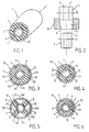
- Figure 1 shows, in perspective, an elastic support of this type, which comprises an external cylindrical sleeve 1 and a internal cylindrical sleeve 2, coaxial, metallic, here in sections circulars; between the two sleeves 1 and 2 is arranged a material elastic 3, such as rubber, secured by bonding 4 to the inner surface of the outer sleeve 1 and the outer surface of the internal sleeve 2.
- a material elastic 3 such as rubber
- FIG. 2 illustrates schematically the most common method used: the support elastic, produced as described above, is forced into the bore 9 of a die 8 of frustoconical shape; after passing through the die 8, the outer diameter 6 of the outer sleeve 1 is less than outside diameter 5 which it had before introduction into the die, this reduction in diameter compressing the rubber 3.
- rubber 3 is the seat of a shrinkage phenomenon due to its vulcanization; diameter reduction must therefore compensate for this withdrawal before we can ensure the rubber compression; we therefore understand that the limitation of reduced to a few percent leads to the creation of a support elastic whose effectiveness is limited, rubber 3 being insufficiently compressed.
- die 8 instead of die 8, a chuck with spaced longitudinal sectors circumferentially, in particular for the production of support elastics with non-circular cross-section, for example polygonal, but the disadvantages mentioned above are the same.
- the present invention relates to an elastic support in which the elastic material is compressed in a degree greater than that known so far, the reduction in diameter cited about the above example of up to twenty percent at instead of five percent, without deterioration of the bonding.
- the subject of the invention is an elastic support comprising at least two cylindrical sleeves with parallel axes, one external and the other internal, linked together by an elastic material in compression, the compression of the elastic material being obtained at least by modification of the length of the straight line of the straight section of said outer sleeve, which is deformable and in contact with said material, changing the length of the middle line of the cross section of said outer sleeve being obtained in the direction which brings the middle lines of the sections radially closer to each other straight of the outer sleeve and the adjacent sleeve, the sleeve external, the mean line of which is modified, presenting tucked in folds longitudinal prepositioned, regularly distributed peripherally, characterized by the fact that the elastic material is not stuck to the surface inside of the outer sleeve only in areas other than those are located to the right of said folds in and those which are located neighborhood of areas.
- the rigidity of the folds inside the outer sleeve is able to maintain compression of the elastic material; we can also foresee that the support according to the invention comprises an intermediate sleeve of the same axis as the outer and inner sleeves, the elastic material being arranged between, on the one hand, the intermediate sleeve and, on the other hand, each of the outer and inner sleeves, and being bonded to the inner surfaces and outside of the intermediate sleeve.
- the mean line of the internal sleeve is modified to present prepositioned longitudinal folds and regularly distributed around the periphery; line modification middle of the inner sleeve creates compression of the material elastic disposed between said inner sleeve and the sleeve intermediate.
- the inner sleeve has a increase up to twenty percent in the length of the middle line of its straight section; the outer sleeve can also present a reduction of up to twenty percent of the length of the middle line of its cross section.
- the tucked folds have adjoining wings.
- the section of at least one of the sleeves is circular or polygonal.
- the invention also relates to a manufacturing process of an elastic support as defined above, comprising at least one external sleeve and an internal cylindrical sleeve of parallel axis linked together by an elastic material, characterized in that it consists in modifying the length of the middle line of the straight section of the outer sleeve by bringing the midlines of the straight sections of the outer sleeve and the adjacent sleeve.
- the method defined above further provides increase by length the average line length of the cross section of the inner sleeve.
- a elastic support according to the present invention, one starts from a internal sleeve 20 cylindrical metal, here of form section general circular, the outer surface of which is coated with an adhesive 4 dries after evaporation of the solvent used to deposit the said adhesive 4 by spraying.
- the inner sleeve 20 is surrounded so concentric with an external sleeve 10, cylindrical, metallic, with circular section.
- the wall of the outer sleeve 10 has folds re-entrant longitudinal sections 111, which are, in fact, primers of more folds important, as will be described below; these folds 111, or fold primers, can be produced by machining, stamping, stamping, drawing, spinning.
- the wall section of the sleeve external 10 to the right of the folds 111 can be of general shape quad deskar, trapezoidal, with sharp or rounded angles.
- the folds 111 are regularly distributed around the periphery of the outer sleeve 10; according to the example shown, there are four folds 111 arranged at eighty ten degrees from each other.
- the two sleeves 10 and 20 are deposited coaxially in a molding machine for the placement by molding of the rubber 3 between the two sleeves 10 and 20: prior to molding, areas 40 are reserved, for example by means of drawers sliding doors provided in the molding machine. These zones 40 are located inside the sleeve 10 to the right 12 of the inside folds 111 and to their neighborhood 13, so that when the rubber 3 is molded between the sleeves 10 and 20, there is no rubber in these zones 40, as shown in figure 3.
- the assembly that comes to be described is forced into a frustoconical die, such as die 8 in FIG. 2, which leads to a reduction in the length of the middle line of the straight section of the sleeve 10, that is to say a reduction in the diameter of the sleeve 10. Thanks to the folds 111 regularly distributed circumferentially, which the sleeve 10, this reduction in diameter takes place symmetrically, the folds 111 being accentuated during this operation until they become folds tucked in 11, the wings of which are contiguous, as shown in the figure 4, but could be non-contiguous.
- the area 31 of the surface thereof which faces the parts 12, 13 of the inner surface of the sleeve 10 is not glued to the sleeve 10 and therefore there is no deterioration bonding in these very mechanically stressed areas during the diameter reduction operation which can be carried out with a rate significant reduction of up to twenty percent.
- Figures 5 and 6 are respectively analogous to Figures 3 and 4 but relate to a variant according to which the zones of reserve 140 are greater, the rubber 3 not surrounding the inner sleeve 20 completely: the rubber 3 is shaped of a plurality of radial arms, here four radial arms.
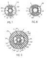
- Figures 7 and 8 show a variant support elastic according to the invention in which the compression of the rubber 3 is obtained not by reducing the length of the middle line of the cross section of the outer sleeve 110 but by an increase in that of the internal link 120.
- an internal sleeve 120 comprising, in FIG. 7, folds outgoing longitudinal 121 regularly distributed peripherally; according to the example shown, the internal sleeve 120 has two folds outgoing 121 arranged at one hundred and eighty degrees.
- the inner sleeve 120 is then subjected to a swaging operation following which the length of the mean line in section of the internal sleeve 120 is increased, the outgoing folds 121 being opened by this operation in generally leaving longitudinal traces 21 called folds out 21.
- the increase in average line length during the expansion can reach up to twenty percent, without deterioration bonding, the material of the inner sleeve 120 not being subject to any lengthening during expansion.
- Figures 9 to 11 relate to another variant of support elastic according to the invention which comprises, in addition to internal sleeves 220 and external 210 similar to those described above in connection Figures 3 to 8, an intermediate sleeve 50 of the same axis as the external 210 and internal 220 sleeves and placed therebetween; on these Figures, the elements of sleeves 220 and 210 similar to those of similar sleeves of the previous figures bear the references that they had on these figures increased by two hundred and will not be described further; rubber 3 is placed between, on the one hand, the intermediate sleeve 50 and, on the other hand, each of the sleeves external 210 and internal 220.
- the rubber 3 is bonded to the sleeves external and internal as in the previous variants, reservations such as 340 and 440 having been provided, and, in addition, on the surfaces inner and outer of the intermediate sleeve 50. According to this variant, the rubber 3 is put in compression by reducing the length of the middle line of the straight section of the outer sleeve 210 and increasing that of the inner sleeve 220.
- Figure 9 represents this variant of elastic support just after molding the rubber 3, the external sleeve 210 being analogous to the sleeve external 10 described with reference to FIG. 3 and the internal sleeve 220 being analogous to the internal sleeve 120 described in connection with FIG. 7.
- FIG. 10 shows the configuration of the elastic support after passage in a die of the external sleeve 210 and FIG. 11 shows the final configuration of the elastic support after expansion of the internal sleeve 220; of course, these two operations, passage in a sector and expansion, can be carried out successively or simultaneously.
Landscapes
- Engineering & Computer Science (AREA)
- General Engineering & Computer Science (AREA)
- Mechanical Engineering (AREA)
- Manufacturing & Machinery (AREA)
- Springs (AREA)
- Support Of The Bearing (AREA)
- Lining Or Joining Of Plastics Or The Like (AREA)
- Gloves (AREA)
- Rigid Pipes And Flexible Pipes (AREA)
Description
- la figure 1 représente en perspective un support élastique de l'état de la technique ;
- la figure 2 illustre schématiquement un procédé de réalisation connu du support élastique de la figure 1 ;
- les figures 3 et 4 sont des vues en coupe transversale d'un support élastique selon l'invention respectivement avant, figure 3, et après, figure 4, mise en compression du matériau élastique, cette mise en compression étant obtenue par diminution de la longueur de la ligne moyenne de la section droite du manchon externe ;
- les figures 5 et 6 sont analogues aux figures 3 et 4 et représentent une variante ;
- les figures 7 et 8 sont des vues en coupe transversale d'un support élastique selon l'invention respectivement avant, figure 7, et après, figure 8, mise en compression du matériau élastique, cette mise en compression étant obtenue par augmentation de la longueur de la ligne moyenne de la section droite du manchon interne ;
- la figure 9 est une vue en coupe transversale d'un support élastique selon l'invention comportant un manchon intermédiaire, avant mise en compression du matériau élastique ;
- la figure 10 représente le support élastique de la figure 9 après une première mise en compression du matériau élastique par diminution de la longueur de la ligne moyenne de la section droite du manchon externe ;
- la figure 11 représente le support élastique de la figure 10 après une deuxième mise en compression du matériau élastique par augmentation de la longueur de la ligne moyenne de la section droite du manchon interne.
Claims (11)
- Support élastique comportant au moins deux manchons (10-210, 20-220) cylindriques d'axes parallèles, l'un externe (10, 210) et l'autre interne (20, 220), liés entre eux par un matériau élastique (3) en compression, la compression du matériau élastique (3) étant obtenue au moins par modification de la longueur de la ligne moyenne de la section droite dudit manchon externe, qui est déformable et en contact avec ledit matériau, la modification de la longueur de la ligne moyenne de la section droite dudit manchon externe étant obtenue dans le sens qui rapproche l'une de l'autre radialement les lignes moyennes des sections droites du manchon externe (10, 210) et du manchon adjacent, le manchon externe (10, 210), dont la ligne moyenne est modifiée, présentant des plis rentrés (11, 211) longitudinaux prépositionnés, régulièrement répartis périphériquement, caractérisé par le fait que le matériau élastique (3) n'est collé à la surface intérieure du manchon externe (10, 210) que dans des zones autres que celles (12) qui sont situées au droit desdits plis rentrés (11, 211) et celles (13) qui sont situées au voisinage des zones (12).
- Support selon la revendication 1, caractérisé par le fait que la rigidité des plis rentrés (11, 211) du manchon externe (10, 210) est apte à maintenir en compression le matériau élastique (3).
- Support selon l'une des revendications 1 ou 2, caractérisé par le fait qu'il comporte un manchon intermédiaire (50) de même axe que les manchons externe (210) et interne (220), le matériau élastique (3) étant disposé entre, d'une part, le manchon intermédiaire (50) et, d'autre part, chacun des manchons externe (210) et interne (220), et étant collé sur les surfaces intérieure et extérieure du manchon intermédiaire (50).
- Support selon l'une des revendications 1 à 3, caractérisé par le fait que la ligne moyenne du manchon interne (220) est modifiée pour présenter des plis sortis (222) longitudinaux prépositionnés et régulièrement répartis périphériquement.
- Support selon les revendications 3 et 4 prises simultanément, caractérisé par le fait que la modification de la ligne moyenne du manchon interne (220) crée une compression du matériau élastique (3) disposé entre ledit manchon interne (220) et le manchon intermédiaire (50).
- Support selon la revendication 4, caractérisé par le fait que le manchon interne (20, 220) présente une augmentation atteignant jusqu'à vingt pour cent de la longueur de la ligne moyenne de sa section droite.
- Support selon l'une des revendications 1 à 6, caractérisé par le fait que les plis rentrés (11, 211) ont des ailes jointives.
- Support selon l'une des revendications 1 à 7, caractérisé par le fait que le manchon externe (10, 210) présente une réduction atteignant jusqu'à vingt pour cent de la longueur de la ligne moyenne de sa section droite.
- Support selon l'une des revendications 1 à 8, caractérisé par le fait que la section de l'un au moins des manchons (10-210, 50, 20-220) est circulaire ou polygonale.
- Procédé de fabrication d'un support élastique comportant au moins un manchon externe (10-210) et un manchon interne (20-220) cylindriques d'axe parallèle liés entre eux par un matériau élastique (3) selon l'une des revendications 1 à 9, caractérisé par le fait qu'il consiste à modifier la longueur de la ligne moyenne de la section droite du manchon externe (10, 210) en rapprochant l'une de l'autre radialement les lignes moyennes des sections droites du manchon externe (10-210) et du manchon adjacent (50, 20-220).
- Procédé selon la revendication 10, caractérisé par le fait qu'il consiste à augmenter, en outre, par dudgeonnage la longueur de la ligne moyenne de la section droite du manchon interne (220).
Applications Claiming Priority (3)
| Application Number | Priority Date | Filing Date | Title |
|---|---|---|---|
| FR9406159A FR2720132B1 (fr) | 1994-05-18 | 1994-05-18 | Support élastique comportant au moins deux manchons cylindriques coaxiaux liés entre eux par un matériau élastique, manchons pour un tel support et procédé de fabrication dudit support. |
| FR9406159 | 1994-05-18 | ||
| PCT/FR1995/000645 WO1995031652A1 (fr) | 1994-05-18 | 1995-05-17 | Support elastique comportant au moins deux manchons cylindriques, manchons pour un tel support et procede de fabrication du support au moyen desdits manchons |
Publications (2)
| Publication Number | Publication Date |
|---|---|
| EP0714484A1 EP0714484A1 (fr) | 1996-06-05 |
| EP0714484B1 true EP0714484B1 (fr) | 1999-10-06 |
Family
ID=9463374
Family Applications (1)
| Application Number | Title | Priority Date | Filing Date |
|---|---|---|---|
| EP95920149A Expired - Lifetime EP0714484B1 (fr) | 1994-05-18 | 1995-05-17 | Support elastique comportant au moins deux manchons cylindriques, manchons pour un tel support et procede de fabrication du support au moyen desdits manchons |
Country Status (10)
| Country | Link |
|---|---|
| EP (1) | EP0714484B1 (fr) |
| JP (1) | JPH09504354A (fr) |
| KR (1) | KR100215142B1 (fr) |
| AT (1) | ATE185407T1 (fr) |
| BR (1) | BR9506202A (fr) |
| CA (1) | CA2166972C (fr) |
| DE (1) | DE69512608T2 (fr) |
| ES (1) | ES2138208T3 (fr) |
| FR (1) | FR2720132B1 (fr) |
| WO (1) | WO1995031652A1 (fr) |
Families Citing this family (12)
| Publication number | Priority date | Publication date | Assignee | Title |
|---|---|---|---|---|
| DE19733478B4 (de) | 1997-08-02 | 2006-03-23 | Daimlerchrysler Ag | Schwingungsdämpfer für eine rohrförmige Gelenkwelle |
| DE10130306C2 (de) * | 2001-06-22 | 2003-07-24 | Zf Boge Gmbh | Dämpfungselement |
| US20060085963A1 (en) * | 2004-10-22 | 2006-04-27 | Paul Balczun | Multiple radial spring rate pivot bushing and method of making |
| JP3951274B1 (ja) * | 2006-02-20 | 2007-08-01 | 東洋ゴム工業株式会社 | 防振ブッシュの製造方法 |
| US8505889B2 (en) | 2007-01-22 | 2013-08-13 | Toyo Tire & Rubber Co., Ltd. | Vibration-isolating bush |
| FR2937701B1 (fr) | 2008-10-29 | 2013-12-06 | Gaby Mameri | Dispositif antivibratoire |
| DE102009022841B4 (de) * | 2009-05-27 | 2013-08-01 | Anvis Deutschland Gmbh | Elastisches Federbeinkopflager für ein Kraftfahrzeug und Verfahren zum Einstellen einer Druckvorspannung in einem elastischen Ringkörper des Federbeinkopflagers |
| DE102015000568A1 (de) * | 2015-01-17 | 2016-07-21 | Audi Ag | Gummi-Metall-Hülsenlager |
| DE102018125199B4 (de) * | 2018-10-11 | 2022-02-10 | Dr. Ing. H.C. F. Porsche Aktiengesellschaft | Mehrteiliges Buchsenlager |
| KR102258238B1 (ko) * | 2019-11-07 | 2021-05-31 | (주)디티알 | 폴더블 마운트 부싱 |
| DE102020007681B3 (de) | 2020-12-15 | 2022-05-05 | Sumitomo Riko Company Limited | Lager, Außenhülse und Verfahren zum Herstellen eines Lagers |
| DE102021213765B4 (de) * | 2021-12-03 | 2024-01-04 | Zf Friedrichshafen Ag | Ringgelenk für eine Gelenkverbindungsanordnung eines Fahrzeugs und Verfahren zu dessen Montage, Gelenkverbindungsanordnung mit dem Ringgelenk und Fahrzeug mit der Gelenkverbindungsanordnung |
Family Cites Families (15)
| Publication number | Priority date | Publication date | Assignee | Title |
|---|---|---|---|---|
| FR680434A (fr) * | 1929-04-06 | 1930-04-29 | Articulation élastique | |
| US2048256A (en) * | 1933-09-15 | 1936-07-21 | Gen Motors Corp | Oscillating pivot joint unit |
| US2509145A (en) * | 1944-11-28 | 1950-05-23 | Lord Mfg Co | Joint |
| US2621923A (en) * | 1947-03-01 | 1952-12-16 | Goodrich Co B F | Rubber spring |
| DE1659989U (de) * | 1952-04-07 | 1953-07-23 | Phaenomen Werke Gustav Hiller | Gummidrehschubfeder fuer hohe spezifische beanspruchungen. |
| GB816311A (en) * | 1956-11-16 | 1959-07-08 | Chrysler Corp | Improvements in or relating to vibration-damping mountings |
| GB869368A (en) * | 1957-09-04 | 1961-05-31 | Wright Howard Clayton Ltd | Improvements relating to resilient bushes |
| DE2841505C2 (de) * | 1978-09-23 | 1983-04-07 | Boge Gmbh, 5208 Eitorf | Hydraulisch dämpfendes Gummilager |
| DE3327817A1 (de) * | 1983-08-02 | 1985-02-14 | Jörn, geb. Roth, Frieda, 7012 Fellbach | Gummi-metall-buchse, insbesondere fuer die lagerung eines stabilisators an einem kraftfahrzeug |
| JPS60256637A (ja) * | 1984-06-02 | 1985-12-18 | Kurashiki Kako Kk | 液体封入サスペンシヨンブツシユ及びその製造方法 |
| JP2783409B2 (ja) * | 1988-10-21 | 1998-08-06 | 株式会社ブリヂストン | 防振装置 |
| JPH04266644A (ja) * | 1991-02-19 | 1992-09-22 | Bridgestone Corp | 防振装置 |
| AU659853B2 (en) * | 1991-08-30 | 1995-06-01 | Neway Corporation | Adjustable bushing |
| DE9112268U1 (de) * | 1991-10-02 | 1991-12-05 | Vorwerk & Sohn Gmbh & Co Kg, 5600 Wuppertal | Schwingungsbuchse, insbesondere für Fahrwerke von Kraftfahrzeugen |
| DE4309425C1 (de) * | 1993-03-24 | 1994-06-01 | Lemfoerder Metallwaren Ag | Gummilager für den Mittelzapfen einer Blattfederaufhängung in einem Kraftfahrzeug |
-
1994
- 1994-05-18 FR FR9406159A patent/FR2720132B1/fr not_active Expired - Fee Related
-
1995
- 1995-05-17 ES ES95920149T patent/ES2138208T3/es not_active Expired - Lifetime
- 1995-05-17 DE DE69512608T patent/DE69512608T2/de not_active Expired - Fee Related
- 1995-05-17 AT AT95920149T patent/ATE185407T1/de not_active IP Right Cessation
- 1995-05-17 CA CA002166972A patent/CA2166972C/fr not_active Expired - Fee Related
- 1995-05-17 JP JP7527419A patent/JPH09504354A/ja not_active Ceased
- 1995-05-17 EP EP95920149A patent/EP0714484B1/fr not_active Expired - Lifetime
- 1995-05-17 BR BR9506202A patent/BR9506202A/pt not_active IP Right Cessation
- 1995-05-17 KR KR1019960700241A patent/KR100215142B1/ko not_active Expired - Fee Related
- 1995-05-17 WO PCT/FR1995/000645 patent/WO1995031652A1/fr not_active Ceased
Also Published As
| Publication number | Publication date |
|---|---|
| ES2138208T3 (es) | 2000-01-01 |
| ATE185407T1 (de) | 1999-10-15 |
| FR2720132B1 (fr) | 1996-07-26 |
| DE69512608D1 (de) | 1999-11-11 |
| CA2166972C (fr) | 1999-07-27 |
| KR100215142B1 (ko) | 1999-08-16 |
| BR9506202A (pt) | 1996-04-23 |
| DE69512608T2 (de) | 2000-05-31 |
| JPH09504354A (ja) | 1997-04-28 |
| FR2720132A1 (fr) | 1995-11-24 |
| KR960704177A (ko) | 1996-08-31 |
| EP0714484A1 (fr) | 1996-06-05 |
| WO1995031652A1 (fr) | 1995-11-23 |
Similar Documents
| Publication | Publication Date | Title |
|---|---|---|
| EP0034549B1 (fr) | Procédé de dudgeonnage et outil susceptible d'être utilisé pour la mise en oeuvre de ce procédé | |
| CA2166972C (fr) | Support elastique comportant au moins deux manchons cylindriques, manchons pour un tel support et procede de fabrication du support au moyen desdits manchons | |
| FR2690208A1 (fr) | Ecrou, notamment écrou pour roue. | |
| FR2818338A1 (fr) | Soufflet d'etancheite, joint de transmission d'un tel soufflet et procede de fixation d'un tel soufflet | |
| EP0737114B1 (fr) | Procede de retreint | |
| FR2848497A1 (fr) | Procede de fabrication d'une enveloppe a soufflets de protection de dispositif de transmission et enveloppe obtenue par la mise en oeuvre du procede | |
| FR2739153A1 (fr) | Articulation elastique, en particulier pour suspension d'un vehicule automobile | |
| FR2601428A1 (fr) | Dispositif d'etancheite destine a realiser l'etancheite au niveau d'une bride | |
| FR2851804A1 (fr) | Bielle anti-vibratoire et son procede de fabrication | |
| FR2601734A1 (fr) | Disque d'embrayage | |
| FR2772875A1 (fr) | Dispositif de raccordement d'un tuyau souple a une paroi, en particulier d'un echangeur de chaleur de vehicule automobile | |
| EP0019256A1 (fr) | Tuyau en fonte ductile à emboîtement | |
| FR2669087A1 (fr) | Bague exterieure de palier de roue. | |
| FR2618090A1 (fr) | Procede de fabrication d'un moyeu d'amortisseur de torsion | |
| EP1478860B1 (fr) | Procede de fixation d'une piece annulaire d'accouplement en materiau elastomerique entre deux tubes emboites l'un dans l'autre, et ensemble obtenu par le procede | |
| EP1317355B1 (fr) | Procede de fixation d'au moins un insert de guidage entre deux tubes coaxiaux, notamment dans un dispositif anti-roulis de vehicule automobile | |
| FR2594205A1 (fr) | Raccord terminal de tuyau souple | |
| EP0192592B1 (fr) | Méthode d'assemblage de flasques de butée sur coussinet lisse par sertissage | |
| FR2775045A1 (fr) | Procede de montage d'un joint souple sur une piece et piece equipee d'un tel joint | |
| EP0656246B1 (fr) | Procédé pour rétreindre une bague à rétreindre placée derrière un obstacle axial et dispositif pour sa mise en oeuvre | |
| EP0537035A1 (fr) | Arbre de transmission à tube composite et son procédé de réalisation | |
| FR2869965A1 (fr) | Ensemble de roulement et joint homocinetique correspondant | |
| EP0661136A1 (fr) | Procédé de rodage de la surface d'une pièce et rodoir pour la mise en oeuvre de ce procédé | |
| FR2750189A1 (fr) | Butee en caoutchouc assurant un amortissement progressif | |
| FR2683772A1 (fr) | Articulation a rotule elastique pour triangle de suspension avant de vehicule. |
Legal Events
| Date | Code | Title | Description |
|---|---|---|---|
| PUAI | Public reference made under article 153(3) epc to a published international application that has entered the european phase |
Free format text: ORIGINAL CODE: 0009012 |
|
| 17P | Request for examination filed |
Effective date: 19951011 |
|
| AK | Designated contracting states |
Kind code of ref document: A1 Designated state(s): AT BE CH DE DK ES FR GB GR IE IT LI LU MC NL PT SE |
|
| 17Q | First examination report despatched |
Effective date: 19970627 |
|
| GRAG | Despatch of communication of intention to grant |
Free format text: ORIGINAL CODE: EPIDOS AGRA |
|
| GRAG | Despatch of communication of intention to grant |
Free format text: ORIGINAL CODE: EPIDOS AGRA |
|
| GRAH | Despatch of communication of intention to grant a patent |
Free format text: ORIGINAL CODE: EPIDOS IGRA |
|
| GRAH | Despatch of communication of intention to grant a patent |
Free format text: ORIGINAL CODE: EPIDOS IGRA |
|
| GRAA | (expected) grant |
Free format text: ORIGINAL CODE: 0009210 |
|
| RAP1 | Party data changed (applicant data changed or rights of an application transferred) |
Owner name: MICHELIN AVS |
|
| AK | Designated contracting states |
Kind code of ref document: B1 Designated state(s): AT BE CH DE DK ES FR GB GR IE IT LI LU MC NL PT SE |
|
| PG25 | Lapsed in a contracting state [announced via postgrant information from national office to epo] |
Ref country code: SE Free format text: THE PATENT HAS BEEN ANNULLED BY A DECISION OF A NATIONAL AUTHORITY Effective date: 19991006 Ref country code: NL Free format text: LAPSE BECAUSE OF FAILURE TO SUBMIT A TRANSLATION OF THE DESCRIPTION OR TO PAY THE FEE WITHIN THE PRESCRIBED TIME-LIMIT Effective date: 19991006 Ref country code: GR Free format text: LAPSE BECAUSE OF NON-PAYMENT OF DUE FEES Effective date: 19991006 Ref country code: AT Free format text: LAPSE BECAUSE OF FAILURE TO SUBMIT A TRANSLATION OF THE DESCRIPTION OR TO PAY THE FEE WITHIN THE PRESCRIBED TIME-LIMIT Effective date: 19991006 |
|
| REF | Corresponds to: |
Ref document number: 185407 Country of ref document: AT Date of ref document: 19991015 Kind code of ref document: T |
|
| REG | Reference to a national code |
Ref country code: CH Ref legal event code: EP |
|
| ITF | It: translation for a ep patent filed | ||
| REF | Corresponds to: |
Ref document number: 69512608 Country of ref document: DE Date of ref document: 19991111 |
|
| GBT | Gb: translation of ep patent filed (gb section 77(6)(a)/1977) |
Effective date: 19991109 |
|
| REG | Reference to a national code |
Ref country code: ES Ref legal event code: FG2A Ref document number: 2138208 Country of ref document: ES Kind code of ref document: T3 |
|
| PG25 | Lapsed in a contracting state [announced via postgrant information from national office to epo] |
Ref country code: PT Free format text: LAPSE BECAUSE OF FAILURE TO SUBMIT A TRANSLATION OF THE DESCRIPTION OR TO PAY THE FEE WITHIN THE PRESCRIBED TIME-LIMIT Effective date: 20000106 Ref country code: DK Free format text: LAPSE BECAUSE OF FAILURE TO SUBMIT A TRANSLATION OF THE DESCRIPTION OR TO PAY THE FEE WITHIN THE PRESCRIBED TIME-LIMIT Effective date: 20000106 |
|
| REG | Reference to a national code |
Ref country code: IE Ref legal event code: FG4D Free format text: FRENCH |
|
| NLV1 | Nl: lapsed or annulled due to failure to fulfill the requirements of art. 29p and 29m of the patents act | ||
| PG25 | Lapsed in a contracting state [announced via postgrant information from national office to epo] |
Ref country code: LU Free format text: LAPSE BECAUSE OF NON-PAYMENT OF DUE FEES Effective date: 20000517 |
|
| PG25 | Lapsed in a contracting state [announced via postgrant information from national office to epo] |
Ref country code: LI Free format text: LAPSE BECAUSE OF NON-PAYMENT OF DUE FEES Effective date: 20000531 Ref country code: CH Free format text: LAPSE BECAUSE OF NON-PAYMENT OF DUE FEES Effective date: 20000531 Ref country code: BE Free format text: LAPSE BECAUSE OF NON-PAYMENT OF DUE FEES Effective date: 20000531 |
|
| PLBE | No opposition filed within time limit |
Free format text: ORIGINAL CODE: 0009261 |
|
| STAA | Information on the status of an ep patent application or granted ep patent |
Free format text: STATUS: NO OPPOSITION FILED WITHIN TIME LIMIT |
|
| 26N | No opposition filed | ||
| PG25 | Lapsed in a contracting state [announced via postgrant information from national office to epo] |
Ref country code: IE Free format text: LAPSE BECAUSE OF NON-PAYMENT OF DUE FEES Effective date: 20001103 |
|
| REG | Reference to a national code |
Ref country code: IE Ref legal event code: FD4D |
|
| BERE | Be: lapsed |
Owner name: MICHELIN AVS Effective date: 20000531 |
|
| PG25 | Lapsed in a contracting state [announced via postgrant information from national office to epo] |
Ref country code: MC Free format text: LAPSE BECAUSE OF NON-PAYMENT OF DUE FEES Effective date: 20001130 |
|
| REG | Reference to a national code |
Ref country code: CH Ref legal event code: PL |
|
| REG | Reference to a national code |
Ref country code: GB Ref legal event code: IF02 |
|
| PGFP | Annual fee paid to national office [announced via postgrant information from national office to epo] |
Ref country code: GB Payment date: 20020502 Year of fee payment: 8 |
|
| PG25 | Lapsed in a contracting state [announced via postgrant information from national office to epo] |
Ref country code: GB Free format text: LAPSE BECAUSE OF NON-PAYMENT OF DUE FEES Effective date: 20030517 |
|
| REG | Reference to a national code |
Ref country code: FR Ref legal event code: CJ |
|
| GBPC | Gb: european patent ceased through non-payment of renewal fee |
Effective date: 20030517 |
|
| PGFP | Annual fee paid to national office [announced via postgrant information from national office to epo] |
Ref country code: DE Payment date: 20040510 Year of fee payment: 10 |
|
| PGFP | Annual fee paid to national office [announced via postgrant information from national office to epo] |
Ref country code: FR Payment date: 20040512 Year of fee payment: 10 |
|
| PGFP | Annual fee paid to national office [announced via postgrant information from national office to epo] |
Ref country code: ES Payment date: 20040518 Year of fee payment: 10 |
|
| PG25 | Lapsed in a contracting state [announced via postgrant information from national office to epo] |
Ref country code: IT Free format text: LAPSE BECAUSE OF NON-PAYMENT OF DUE FEES Effective date: 20050517 |
|
| PG25 | Lapsed in a contracting state [announced via postgrant information from national office to epo] |
Ref country code: ES Free format text: LAPSE BECAUSE OF NON-PAYMENT OF DUE FEES Effective date: 20050518 |
|
| PG25 | Lapsed in a contracting state [announced via postgrant information from national office to epo] |
Ref country code: DE Free format text: LAPSE BECAUSE OF NON-PAYMENT OF DUE FEES Effective date: 20051201 |
|
| PG25 | Lapsed in a contracting state [announced via postgrant information from national office to epo] |
Ref country code: FR Free format text: LAPSE BECAUSE OF NON-PAYMENT OF DUE FEES Effective date: 20060131 |
|
| REG | Reference to a national code |
Ref country code: FR Ref legal event code: ST Effective date: 20060131 |
|
| REG | Reference to a national code |
Ref country code: ES Ref legal event code: FD2A Effective date: 20050518 |