EP0713932B1 - Elektrode mit plattenförmigem Elektrodenkörper - Google Patents
Elektrode mit plattenförmigem Elektrodenkörper Download PDFInfo
- Publication number
- EP0713932B1 EP0713932B1 EP95113065A EP95113065A EP0713932B1 EP 0713932 B1 EP0713932 B1 EP 0713932B1 EP 95113065 A EP95113065 A EP 95113065A EP 95113065 A EP95113065 A EP 95113065A EP 0713932 B1 EP0713932 B1 EP 0713932B1
- Authority
- EP
- European Patent Office
- Prior art keywords
- electrode
- plastic body
- carrier
- electrode according
- fixing
- Prior art date
- Legal status (The legal status is an assumption and is not a legal conclusion. Google has not performed a legal analysis and makes no representation as to the accuracy of the status listed.)
- Expired - Lifetime
Links
- 239000004033 plastic Substances 0.000 claims abstract description 44
- 229920003023 plastic Polymers 0.000 claims abstract description 44
- 229910052751 metal Inorganic materials 0.000 claims abstract description 24
- 239000002184 metal Substances 0.000 claims abstract description 24
- 238000000576 coating method Methods 0.000 claims abstract description 12
- 239000011248 coating agent Substances 0.000 claims abstract description 11
- 230000007797 corrosion Effects 0.000 claims abstract description 11
- 238000005260 corrosion Methods 0.000 claims abstract description 11
- 239000000463 material Substances 0.000 claims abstract description 11
- 210000004027 cell Anatomy 0.000 claims description 9
- 210000002421 cell wall Anatomy 0.000 claims description 5
- 239000003792 electrolyte Substances 0.000 abstract description 8
- 229910000831 Steel Inorganic materials 0.000 description 7
- 239000010959 steel Substances 0.000 description 7
- RTAQQCXQSZGOHL-UHFFFAOYSA-N Titanium Chemical compound [Ti] RTAQQCXQSZGOHL-UHFFFAOYSA-N 0.000 description 4
- 239000010936 titanium Substances 0.000 description 4
- 229910052719 titanium Inorganic materials 0.000 description 4
- XKRFYHLGVUSROY-UHFFFAOYSA-N Argon Chemical compound [Ar] XKRFYHLGVUSROY-UHFFFAOYSA-N 0.000 description 2
- IJGRMHOSHXDMSA-UHFFFAOYSA-N Atomic nitrogen Chemical compound N#N IJGRMHOSHXDMSA-UHFFFAOYSA-N 0.000 description 2
- RYGMFSIKBFXOCR-UHFFFAOYSA-N Copper Chemical compound [Cu] RYGMFSIKBFXOCR-UHFFFAOYSA-N 0.000 description 2
- PXHVJJICTQNCMI-UHFFFAOYSA-N Nickel Chemical compound [Ni] PXHVJJICTQNCMI-UHFFFAOYSA-N 0.000 description 2
- -1 Polyethylene Polymers 0.000 description 2
- 239000004698 Polyethylene Substances 0.000 description 2
- 239000004743 Polypropylene Substances 0.000 description 2
- 229910052782 aluminium Inorganic materials 0.000 description 2
- XAGFODPZIPBFFR-UHFFFAOYSA-N aluminium Chemical compound [Al] XAGFODPZIPBFFR-UHFFFAOYSA-N 0.000 description 2
- 238000005253 cladding Methods 0.000 description 2
- 239000004020 conductor Substances 0.000 description 2
- 229910052802 copper Inorganic materials 0.000 description 2
- 239000010949 copper Substances 0.000 description 2
- 230000000694 effects Effects 0.000 description 2
- 238000009713 electroplating Methods 0.000 description 2
- 239000007789 gas Substances 0.000 description 2
- 229920000573 polyethylene Polymers 0.000 description 2
- 229910001069 Ti alloy Inorganic materials 0.000 description 1
- HCHKCACWOHOZIP-UHFFFAOYSA-N Zinc Chemical compound [Zn] HCHKCACWOHOZIP-UHFFFAOYSA-N 0.000 description 1
- 239000000956 alloy Substances 0.000 description 1
- 229910052786 argon Inorganic materials 0.000 description 1
- 238000005422 blasting Methods 0.000 description 1
- 239000002826 coolant Substances 0.000 description 1
- 238000013016 damping Methods 0.000 description 1
- 230000008021 deposition Effects 0.000 description 1
- 238000004090 dissolution Methods 0.000 description 1
- 239000003365 glass fiber Substances 0.000 description 1
- 238000009434 installation Methods 0.000 description 1
- 238000004519 manufacturing process Methods 0.000 description 1
- 229910001092 metal group alloy Inorganic materials 0.000 description 1
- 229910021645 metal ion Inorganic materials 0.000 description 1
- 150000002739 metals Chemical class 0.000 description 1
- 238000000034 method Methods 0.000 description 1
- 239000000203 mixture Substances 0.000 description 1
- 229910052759 nickel Inorganic materials 0.000 description 1
- 229910052757 nitrogen Inorganic materials 0.000 description 1
- 229920001155 polypropylene Polymers 0.000 description 1
- 230000001681 protective effect Effects 0.000 description 1
- 230000007420 reactivation Effects 0.000 description 1
- 238000005096 rolling process Methods 0.000 description 1
- 125000006850 spacer group Chemical group 0.000 description 1
- 239000000725 suspension Substances 0.000 description 1
- 229920001169 thermoplastic Polymers 0.000 description 1
- 239000004416 thermosoftening plastic Substances 0.000 description 1
- 229910052725 zinc Inorganic materials 0.000 description 1
- 239000011701 zinc Substances 0.000 description 1
Images


Classifications
-
- C—CHEMISTRY; METALLURGY
- C25—ELECTROLYTIC OR ELECTROPHORETIC PROCESSES; APPARATUS THEREFOR
- C25D—PROCESSES FOR THE ELECTROLYTIC OR ELECTROPHORETIC PRODUCTION OF COATINGS; ELECTROFORMING; APPARATUS THEREFOR
- C25D17/00—Constructional parts, or assemblies thereof, of cells for electrolytic coating
- C25D17/10—Electrodes, e.g. composition, counter electrode
- C25D17/12—Shape or form
-
- C—CHEMISTRY; METALLURGY
- C25—ELECTROLYTIC OR ELECTROPHORETIC PROCESSES; APPARATUS THEREFOR
- C25B—ELECTROLYTIC OR ELECTROPHORETIC PROCESSES FOR THE PRODUCTION OF COMPOUNDS OR NON-METALS; APPARATUS THEREFOR
- C25B9/00—Cells or assemblies of cells; Constructional parts of cells; Assemblies of constructional parts, e.g. electrode-diaphragm assemblies; Process-related cell features
- C25B9/60—Constructional parts of cells
- C25B9/65—Means for supplying current; Electrode connections; Electric inter-cell connections
-
- C—CHEMISTRY; METALLURGY
- C25—ELECTROLYTIC OR ELECTROPHORETIC PROCESSES; APPARATUS THEREFOR
- C25D—PROCESSES FOR THE ELECTROLYTIC OR ELECTROPHORETIC PRODUCTION OF COATINGS; ELECTROFORMING; APPARATUS THEREFOR
- C25D17/00—Constructional parts, or assemblies thereof, of cells for electrolytic coating
- C25D17/008—Current shielding devices
-
- C—CHEMISTRY; METALLURGY
- C25—ELECTROLYTIC OR ELECTROPHORETIC PROCESSES; APPARATUS THEREFOR
- C25D—PROCESSES FOR THE ELECTROLYTIC OR ELECTROPHORETIC PRODUCTION OF COATINGS; ELECTROFORMING; APPARATUS THEREFOR
- C25D17/00—Constructional parts, or assemblies thereof, of cells for electrolytic coating
- C25D17/06—Suspending or supporting devices for articles to be coated
Definitions
- the invention relates to an electrode with a plate-shaped electrode carrier for use in a electrolytic cell with corrosion-resistant support, spring element, positioning element or flow guide element opposite a cell wall, in particular an electrode Arrangement for the galvanic coating of continuous strip material, which acts as an electrode carrier has a core made of electrically good conductive material, which is covered by a sheathing is surrounded by valve metal and electrically and mechanically with externally activated electrode parts is firmly connected.
- EP-B 0436 078 describes an anode arrangement with a plate-shaped anode made of valve metal Known with an active surface for electrolytic processes, especially for deposition of metal from metal ion-containing solution on a base, which with a Valve metal power supply is connected; the current is from the outside via well conductive Metals such as Copper, aluminum or steel are fed into the electrolytic cell, the Current through a support immersed in the electrolyte with valve casing to the applied plate-shaped anodes is guided.
- Such electrode or anode arrangements are used, for example, in systems for electrolytic Coil coating used, in which, for example, the continuous metal strip is connected cathodically and a coating with zinc or nickel is carried out; a such coil coating system or steel coil coating system is from EP-B 142 010 or EP-B 167 790 known.
- the invention has the task of the applied casing made of valve metal to protect against mechanical damage, such as in galvanic containers, for example through fixed and / or resilient support elements or flow guide elements to prevent.
- mechanical damage such as in galvanic containers
- fixed and / or resilient support elements or flow guide elements to prevent.
- a spring-like valve metal sheet which serves as a support and flow line is used and rests directly on the valve metal sheath of the electrode.
- the object of the invention is for an electrode arrangement in which support means, spring elements, Positioning elements or flow guiding elements, which come from the cell wall starting from the valve metal casing of the electrode holder, touch the electrode holder to be designed in such a way that, even with hard alloy material, the firm and / or resilient support means, no damage to the valve metal cover of the electrode carrier can arise.
- Electrode carrier the use of thermoplastics as a plastic body for vibration damping in the electrolyte and thus reduces wear on thinner ones Components such as the valve metal cladding occurs.
- fixing elements are designed as part of fastening elements of the active electrode parts, the plastic body on the side of the casing facing away from the electrode parts of the electrode carrier are applied.
- a major advantage of this configuration is the fact that the required anyway Fastening or screwing elements for the active electrode parts additionally as Fasteners for the plastic body are used, so that in practice only a small one Additional effort in material and work is required; furthermore it proves to be advantageous that the plastic body can be easily removed if the reactivation of the concerned Electrode should be required.
- the screwing elements are with recesses provided, engage in the fixing elements for the plastic body; here it proves It is an advantage that the plastic body is already galvanic on the electrode carrier Systems can be applied subsequently, so that here a low-wear in a simple manner Operation is made possible.
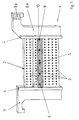
- the electrode 1 consists of a plate-shaped electrode carrier 2, which consists of three carrier plates 3 is assembled, a double-sided bracket 4 with side bracket arms 7, 8a, whereby the carrier plates 3 are combined on both side edges and a current feed 8b; the electrode also includes those that are not visible in the figure active electrode parts, and their fasteners 5 on the electrode parts opposite side of the electrode carrier 2, and one by means of fastening elements 5 and fixing elements 9 positioned plastic body 6, which is designed in the form of a plastic strip.
- the electrode carrier 2 or the carrier plates 3 consist of an electrode base frame made of electrically good conductive material and a casing made of valve metal, preferably made of Titanium sheet, which the enclosed electrically highly conductive metal, for example steel Corrosion protects.
- the two side bracket arms 7, 8a of the bracket 4 serve with their horizontally extending arms of the suspension within the electrochemical cell vessel, wherein a compressed gas connection for flooding the interior of the envelopes of the carrier plates 3 is provided.
- the power supply is in the form of Waveguides formed so that there is a channel for the supply of coolants.
- the bracket arms are made of glass fiber plastic.
- the carrier plate 3 of the electrode carrier consists of a base frame 11 made of electrically highly conductive mechanically stable material, such as steel and one thereupon coating made of a valve metal sheet 12 to the material of the To protect the base frame from corrosion by the electrolyte.
- the basic structure Such an electrode arrangement is described in EP-B 436 078.
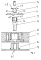
- Active electrode part 13 shown schematically with a welded-on contact socket 14 made of valve metal, which has an internal thread 15 and by means of an Allen screw 16 is attached to the electrode carrier, with hexagon socket screw 16 in its Head area has a welded threaded bushing 17 and an internal thread 18.
- In the internal thread 18 engages in the profile T-shaped fixing screw 9, which through an opening 10 of the plastic body 6 designed as a plastic strip is guided.
- For better Adjustment and counter-mounting of the fixing screw 9 are two recesses 19 in their Head area provided.
- the plastic body 6 shown in the cross-sectional profile lies with its two side flanks 22, 23 on the flat area 34 of the casing 12 or curved by the internal pressure made of valve metal, while the fixing element 9 in the internal thread 18 with the threaded sleeve 17 welded Allen screw 16 engages so that the enlarged head 21 of the Fixing element 9, the flange-like depression extending to the center of the opening 10 25 of the plastic body 6 presses against the casing 12 of the electrode carrier 2, wherein the actual fastening by tightening the fixing element designed as a fixing screw with the help of the recesses 19.
- a locking or securing the entire Fixing screw 9 can be screwed in coaxially after fixing by means of the valve metal Grub screw 35 reached. This also provides security against independent loosening of the fixing element 9.
- the cross section according to FIG. 2a shows that when applying the plastic body 6 no corrosion-prone parts of the Base frame 11 are exposed to the outer electrolyte area.
- sections of the plastic body are recognizable with double-row and simple fastening openings 10, for the purpose of sliding are formed as elongated holes due to thermal expansion; in section A-B and C-D the respective cross section of the plastic strip is shown enlarged.
- the embodiment with double-row fastening openings is particularly suitable for large-format plastic bodies suitable.
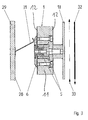
- FIG. 3 shows a part of an electrolytic cell for electroplating, broken away in section of continuous strip material together with that also shown broken Electrode, as is known for example from EP-PS 142 010.
- Electrode 1 with its back and thus with the plastic body 6 to the wall 28 of the partially illustrated cell for electrolytic applications 29 aligned; for spacing opposite the cell wall and for flow regulation is an over the entire electrode width extending spring element or flow guide element 31 is provided which consists of a corrosion-resistant valve metal alloy, preferably a hard titanium alloy; the spring or flow guide element is also used as a support means or positioning element intended.
- PE polyethylene
- PP plastic body
- FIG. 4 schematically shows the composition in a fragmentary exploded drawing the components for fixing the plastic body 6 and the active electrode parts 13; the active electrode part 13 is welded to a T-shaped flange 14 which has an internal thread 15 for screwing in the hexagon socket screw serving as fastening element 6 16; the hexagon socket screw 16 is welded in its head area Provided threaded bushing 17, in whose internal thread 18 the fixing screw which is T-shaped in profile 9 can be screwed in; between the plate-like flange of the head 21 of the fixing screw 9 and the sheath 12 of the electrode carrier, the plastic body 6 is fixed, wherein the flange of the fixing screw on the flange-like recess 25 of the plastic body 6 lies on.
- grub screw 35 is provided for the fixing element, which at Installation through an internal thread 24 of the fixing element on the head surface of the hexagon socket is pressed and thus the fixing element 9 using the counter effect permanently locked; the counter effect is based on the bracing applied by means of counterforce of thread 24; the head of the grub screw is supported on the inside or head surface 26 of the hexagon socket 16 and tensions the thread 24, since in the assembled state there is a torque.
Landscapes
- Chemical & Material Sciences (AREA)
- Organic Chemistry (AREA)
- Chemical Kinetics & Catalysis (AREA)
- Electrochemistry (AREA)
- Materials Engineering (AREA)
- Metallurgy (AREA)
- Engineering & Computer Science (AREA)
- Electrolytic Production Of Metals (AREA)
- Electroplating Methods And Accessories (AREA)
- Battery Electrode And Active Subsutance (AREA)
- Secondary Cells (AREA)
- Hybrid Cells (AREA)
- Prevention Of Electric Corrosion (AREA)
Description
Claims (11)
- Elektrode mit plattenförmigem Elektrodenträger zum Einsatz in einer elektrolytischen Zelle mit korrosionsbeständigem Abstützmittel, Federelement, Positionierelement oder Strömungsleitelement gegenüber einer Zellenwand, insbesondere Elektrode einer Anordnung zur galvanischen Beschichtung durchlaufenden Bandmaterials, die als Elektrodenträger einen Kern aus elektrisch gut leitendem Werkstoff aufweist, der von einer Ummantelung aus Ventilmetall umgeben ist und mit äußeren aktivierten Elektrodenteilen elektrisch und mechanisch fest verbunden ist, dadurch gekennzeichnet, daß auf der dem Abstützmittel, Federelement, Positionierelement oder dem Strömungsleitelement (31) zugewandten Seite der Elektrode (1) ein korrosionsbeständiger Kunststoffkörper (6), aufgebracht ist, der mittels korrosionsbeständiger Befestigungselemente (5) befestigt ist, wobei der Kunststoffkörper zwecks thermischer Ausdehnungsmöglichkeit parallel zur Plattenebene der Elektrode verschiebbar gelagert ist.
- Elektrode nach Anspruch 1, dadurch gekennzeichnet, daß der Kunststoffkörper (6) durch ein in Ausnehmungen der Befestigungselemente (5) einsetzbares und arretierbares Fixierelement (9) mit T-förmigem Profil auf dem Elektrodenträger (2) gehalten ist.
- Elektrode nach Anspruch 1 oder 2, dadurch gekennzeichnet, daß die Fixierelemente (9) als Teil von Befestigungselementen (5) für die aktiven Elektrodenteile (13) ausgebildet sind, wobei der Kunststoffkörper (6) auf der den einseitig aufgebrachten Elektrodenteilen abgewandten Seite des Elektrodenträgers (2) aufgebracht ist.
- Elektrode nach Anspruch 2 oder 3, dadurch gekennzeichnet, daß die Befestigungselemente (5) Innengewinde aufweisen, in die die Fixierelemente (9) zur Halterung bei gleichzeitiger Fixierung der Kunststoffkörper (6) eingeschraubt sind.
- Elektrode nach einem der Ansprüche 1 bis 4, dadurch gekennzeichnet, daß der Elektrodenträger als einteilige Trägerplatte ausgebildet ist.
- Elektrode nach einem der Ansprüche 1 bis 4, dadurch gekennzeichnet, daß der Elektrodenträger (2) in wenigstens zwei Trägerplatten (3) unterteilt ist, von denen wenigstens eine Trägerplatte (3) mit dem Kunststoffkörper (6) versehen ist.
- Elektrode nach einem der Ansprüche 1 bis 6, dadurch gekennzeichnet, daß der Kunststoffkörper (6) als langgestreckte, im Verhältnis von Breite zu Länge schmale Kunststoffleiste ausgebildet ist, deren Längsachse im wesentlichen horizontal angeordnet ist.
- Elektrode nach Anspruch 7, dadurch gekennzeichnet, daß der Kunststoffkörper durchgängige Bohrungen, in Form von Langlöchem aufweist, durch die Fixierelemente (9) geführt sind, welche im Innengewinde der Befestigungselemente (5) für die aktiven Elektrodenteile (13) eingesetzt sind.
- Elektrode nach Anspruch 8, dadurch gekennzeichnet, daß die Langlochbohrungen des Kunststoffkörpers (6) zwecks Verschiebbarkeit und Längenausdehnung gemäß dem Temperaturausdehnungskoeffizienten sich in horizontaler Richtung erstrecken.
- Elektrode nach Anspruch 9, dadurch gekennzeichnet, daß zur Anpassung der Auflage des Kunststoffkörpers an die druckbedingte Ausdehnung der lose aufliegenden Ummantelung, die Fixierelemente (9) in axialer Richtung arretierbar und mittels einer in den Kopf (21) des Fixierelements axial einsetzbaren Madenschraube (35) gegen Lösen gesichert sind.
- Elektrode nach einem der Ansprüche 6 bis 10, dadurch gekennzeichnet, daß der Kunststoffkörper (6) im eingebauten Zustand gegen das an der Zellenwand befestigte Abstützmittel, Positionierelement, Federelement oder Strömungsleitelement (31) stoßend angeordnet ist.
Applications Claiming Priority (2)
| Application Number | Priority Date | Filing Date | Title |
|---|---|---|---|
| DE4442388A DE4442388C2 (de) | 1994-11-29 | 1994-11-29 | Elektrode mit plattenförmigem Elektrodenträger |
| DE4442388 | 1994-11-29 |
Publications (2)
| Publication Number | Publication Date |
|---|---|
| EP0713932A1 EP0713932A1 (de) | 1996-05-29 |
| EP0713932B1 true EP0713932B1 (de) | 1998-01-21 |
Family
ID=6534402
Family Applications (1)
| Application Number | Title | Priority Date | Filing Date |
|---|---|---|---|
| EP95113065A Expired - Lifetime EP0713932B1 (de) | 1994-11-29 | 1995-08-19 | Elektrode mit plattenförmigem Elektrodenkörper |
Country Status (6)
| Country | Link |
|---|---|
| US (1) | US5733424A (de) |
| EP (1) | EP0713932B1 (de) |
| JP (1) | JPH08209397A (de) |
| KR (1) | KR960017929A (de) |
| AT (1) | ATE162560T1 (de) |
| DE (2) | DE4442388C2 (de) |
Families Citing this family (3)
| Publication number | Priority date | Publication date | Assignee | Title |
|---|---|---|---|---|
| JP3606932B2 (ja) * | 1994-12-30 | 2005-01-05 | 石福金属興業株式会社 | 電解用複合電極 |
| US5849164A (en) * | 1996-06-27 | 1998-12-15 | Eltech Systems Corporation | Cell with blade electrodes and recirculation chamber |
| CN114703507B (zh) * | 2022-03-15 | 2024-10-18 | 洛阳双瑞精铸钛业有限公司 | 一种钛铝钛电解锌阴极板 |
Family Cites Families (8)
| Publication number | Priority date | Publication date | Assignee | Title |
|---|---|---|---|---|
| ATE31560T1 (de) * | 1983-11-10 | 1988-01-15 | Hoesch Ag | Verfahren und vorrichtung zum elektrolytischen abscheiden von metallen. |
| DE3421480A1 (de) * | 1984-06-08 | 1985-12-12 | Conradty GmbH & Co Metallelektroden KG, 8505 Röthenbach | Beschichtete ventilmetall-elektrode zur elektrolytischen galvanisierung |
| US4708888A (en) * | 1985-05-07 | 1987-11-24 | Eltech Systems Corporation | Coating metal mesh |
| DE3726674A1 (de) * | 1987-08-11 | 1989-02-23 | Heraeus Elektroden | Elektrodenstruktur fuer elektrochemische zellen |
| JP2722259B2 (ja) * | 1989-09-14 | 1998-03-04 | ペルメレック電極株式会社 | 電極保護体 |
| CA2028759A1 (en) * | 1989-11-22 | 1991-05-23 | Jean-Marie Cassal | Steroids |
| DE3940044C2 (de) | 1989-12-04 | 1994-08-11 | Heraeus Elektrochemie | Anodenanordnung für elektrolytische Prozesse |
| US5531873A (en) * | 1990-06-20 | 1996-07-02 | Savcor-Consulting Oy | Electrode arrangement to be used in the cathodic protection of concrete structures and a fixing element |
-
1994
- 1994-11-29 DE DE4442388A patent/DE4442388C2/de not_active Expired - Fee Related
-
1995
- 1995-08-19 EP EP95113065A patent/EP0713932B1/de not_active Expired - Lifetime
- 1995-08-19 DE DE59501327T patent/DE59501327D1/de not_active Expired - Fee Related
- 1995-08-19 AT AT95113065T patent/ATE162560T1/de not_active IP Right Cessation
- 1995-11-15 US US08/558,829 patent/US5733424A/en not_active Expired - Fee Related
- 1995-11-25 KR KR1019950043762A patent/KR960017929A/ko not_active Withdrawn
- 1995-11-28 JP JP7309113A patent/JPH08209397A/ja active Pending
Also Published As
| Publication number | Publication date |
|---|---|
| KR960017929A (ko) | 1996-06-17 |
| JPH08209397A (ja) | 1996-08-13 |
| DE4442388A1 (de) | 1996-05-30 |
| DE4442388C2 (de) | 1999-01-07 |
| US5733424A (en) | 1998-03-31 |
| EP0713932A1 (de) | 1996-05-29 |
| DE59501327D1 (de) | 1998-02-26 |
| ATE162560T1 (de) | 1998-02-15 |
Similar Documents
| Publication | Publication Date | Title |
|---|---|---|
| DE102009030017A1 (de) | Vorrichtung zur Spannungsversorgung eines Kraftfahrzeugs mit einem Kühlerblock | |
| EP0685658A2 (de) | Haltevorrichtung für eine Mutter | |
| DE19723455C1 (de) | Aluminium-Elektrolytkondensator | |
| DE4442388C2 (de) | Elektrode mit plattenförmigem Elektrodenträger | |
| DE3150469C2 (de) | Vorrichtung zum Galvanisieren eines Rotations-Druckzylinders | |
| DE3940044C2 (de) | Anodenanordnung für elektrolytische Prozesse | |
| DE102007052415A1 (de) | Modulträger mit einer Trägerstruktur für mindestens ein Photovoltaikmodul | |
| DE29804559U1 (de) | Mechanisches Verbindungselement | |
| EP0690151B1 (de) | Elektrode zum Galvanischen Beschichten von Bauteilen | |
| DE68913339T2 (de) | Verriegelungseinrichtung für Batteriepole und Gehäuse. | |
| DE202019104173U1 (de) | Vorrichtung zum Befestigen eines ersten Bauteils an einem zweiten Bauteil | |
| DE102024137037B3 (de) | Verbindungsanordnung, Gehäuseanordnung und Fahrzeug | |
| DE102012214162A1 (de) | Multifunktionales Befestigungsprofil | |
| DE19603511A1 (de) | Wagenkasten eines Schienenfahrzeuges mit Erdungsteilen | |
| DE10203240B4 (de) | Kühlvorrichtung für ein heisses langgestrecktes Metallgut | |
| DE102023004058A1 (de) | Halterungsvorrichtung und Akkumulator | |
| DE102021205252B4 (de) | Batteriegehäuse, Batterie und Kraftfahrzeug mit einer Batterie | |
| DE29701337U1 (de) | Anordnung zur Befestigung eines Gasgenerators, insbesondere eines Rohrgasgenerators in einem Gehäuse, insbesondere in einem Diffusor eines Airbagmoduls | |
| DE102012016495A1 (de) | Vorrichtung zum Verbinden von mindestens zwei Bauteilen | |
| DE19939968B4 (de) | Seitenverkleidungsbefestigung | |
| DE102022109602A1 (de) | Antriebssystem für ein wenigstens teilweise elektrisch angetriebenes Kraftfahrzeug | |
| DE3242546A1 (de) | Klemme zum halten eines werkstueckes bei einer elektrolytischen behandlung | |
| DE9314572U1 (de) | Band für Türen, Fenster u.dgl. | |
| DE2652671A1 (de) | Schraubverbindung zur elektrischen und mechanischen verbindung der blechteile einer leuchte | |
| DE3305440A1 (de) | Stossfaenger |
Legal Events
| Date | Code | Title | Description |
|---|---|---|---|
| PUAI | Public reference made under article 153(3) epc to a published international application that has entered the european phase |
Free format text: ORIGINAL CODE: 0009012 |
|
| 17P | Request for examination filed |
Effective date: 19950901 |
|
| AK | Designated contracting states |
Kind code of ref document: A1 Designated state(s): AT BE DE GB IT LU NL SE |
|
| GRAG | Despatch of communication of intention to grant |
Free format text: ORIGINAL CODE: EPIDOS AGRA |
|
| 17Q | First examination report despatched |
Effective date: 19970513 |
|
| GRAG | Despatch of communication of intention to grant |
Free format text: ORIGINAL CODE: EPIDOS AGRA |
|
| GRAH | Despatch of communication of intention to grant a patent |
Free format text: ORIGINAL CODE: EPIDOS IGRA |
|
| GRAH | Despatch of communication of intention to grant a patent |
Free format text: ORIGINAL CODE: EPIDOS IGRA |
|
| GRAA | (expected) grant |
Free format text: ORIGINAL CODE: 0009210 |
|
| AK | Designated contracting states |
Kind code of ref document: B1 Designated state(s): AT BE DE GB IT LU NL SE |
|
| REF | Corresponds to: |
Ref document number: 162560 Country of ref document: AT Date of ref document: 19980215 Kind code of ref document: T |
|
| GBT | Gb: translation of ep patent filed (gb section 77(6)(a)/1977) |
Effective date: 19980126 |
|
| REF | Corresponds to: |
Ref document number: 59501327 Country of ref document: DE Date of ref document: 19980226 |
|
| ITF | It: translation for a ep patent filed | ||
| PGFP | Annual fee paid to national office [announced via postgrant information from national office to epo] |
Ref country code: DE Payment date: 19980629 Year of fee payment: 4 |
|
| PGFP | Annual fee paid to national office [announced via postgrant information from national office to epo] |
Ref country code: SE Payment date: 19980709 Year of fee payment: 4 |
|
| PGFP | Annual fee paid to national office [announced via postgrant information from national office to epo] |
Ref country code: AT Payment date: 19980817 Year of fee payment: 4 |
|
| PG25 | Lapsed in a contracting state [announced via postgrant information from national office to epo] |
Ref country code: LU Free format text: LAPSE BECAUSE OF NON-PAYMENT OF DUE FEES Effective date: 19980819 |
|
| PGFP | Annual fee paid to national office [announced via postgrant information from national office to epo] |
Ref country code: BE Payment date: 19980911 Year of fee payment: 4 |
|
| PLBE | No opposition filed within time limit |
Free format text: ORIGINAL CODE: 0009261 |
|
| STAA | Information on the status of an ep patent application or granted ep patent |
Free format text: STATUS: NO OPPOSITION FILED WITHIN TIME LIMIT |
|
| 26N | No opposition filed | ||
| PG25 | Lapsed in a contracting state [announced via postgrant information from national office to epo] |
Ref country code: GB Free format text: LAPSE BECAUSE OF NON-PAYMENT OF DUE FEES Effective date: 19990819 Ref country code: AT Free format text: LAPSE BECAUSE OF NON-PAYMENT OF DUE FEES Effective date: 19990819 |
|
| PG25 | Lapsed in a contracting state [announced via postgrant information from national office to epo] |
Ref country code: SE Free format text: THE PATENT HAS BEEN ANNULLED BY A DECISION OF A NATIONAL AUTHORITY Effective date: 19990830 |
|
| PG25 | Lapsed in a contracting state [announced via postgrant information from national office to epo] |
Ref country code: BE Free format text: LAPSE BECAUSE OF NON-PAYMENT OF DUE FEES Effective date: 19990831 |
|
| BERE | Be: lapsed |
Owner name: HERAEUS ELEKTROCHEMIE G.M.B.H. Effective date: 19990831 |
|
| PG25 | Lapsed in a contracting state [announced via postgrant information from national office to epo] |
Ref country code: NL Free format text: LAPSE BECAUSE OF NON-PAYMENT OF DUE FEES Effective date: 20000301 |
|
| GBPC | Gb: european patent ceased through non-payment of renewal fee |
Effective date: 19990819 |
|
| EUG | Se: european patent has lapsed |
Ref document number: 95113065.7 |
|
| NLV4 | Nl: lapsed or anulled due to non-payment of the annual fee |
Effective date: 20000301 |
|
| PG25 | Lapsed in a contracting state [announced via postgrant information from national office to epo] |
Ref country code: DE Free format text: LAPSE BECAUSE OF NON-PAYMENT OF DUE FEES Effective date: 20000601 |
|
| PG25 | Lapsed in a contracting state [announced via postgrant information from national office to epo] |
Ref country code: IT Free format text: LAPSE BECAUSE OF NON-PAYMENT OF DUE FEES;WARNING: LAPSES OF ITALIAN PATENTS WITH EFFECTIVE DATE BEFORE 2007 MAY HAVE OCCURRED AT ANY TIME BEFORE 2007. THE CORRECT EFFECTIVE DATE MAY BE DIFFERENT FROM THE ONE RECORDED. Effective date: 20050819 |