EP0713232B1 - Chambre de coupure d'un disjoncteur électrique - Google Patents
Chambre de coupure d'un disjoncteur électrique Download PDFInfo
- Publication number
- EP0713232B1 EP0713232B1 EP19950410128 EP95410128A EP0713232B1 EP 0713232 B1 EP0713232 B1 EP 0713232B1 EP 19950410128 EP19950410128 EP 19950410128 EP 95410128 A EP95410128 A EP 95410128A EP 0713232 B1 EP0713232 B1 EP 0713232B1
- Authority
- EP
- European Patent Office
- Prior art keywords
- movable contact
- mentioned
- arc
- coolers
- chamber according
- Prior art date
- Legal status (The legal status is an assumption and is not a legal conclusion. Google has not performed a legal analysis and makes no representation as to the accuracy of the status listed.)
- Expired - Lifetime
Links
- 230000015572 biosynthetic process Effects 0.000 claims description 5
- 239000007789 gas Substances 0.000 claims description 3
- 239000000919 ceramic Substances 0.000 claims description 2
- 238000001704 evaporation Methods 0.000 claims description 2
- 230000008020 evaporation Effects 0.000 claims description 2
- 239000002184 metal Substances 0.000 claims description 2
- 238000001816 cooling Methods 0.000 description 6
- 230000008033 biological extinction Effects 0.000 description 4
- 238000000926 separation method Methods 0.000 description 3
- 230000000712 assembly Effects 0.000 description 2
- 238000000429 assembly Methods 0.000 description 2
- 238000011536 re-plating Methods 0.000 description 2
- 230000008034 disappearance Effects 0.000 description 1
- 238000006073 displacement reaction Methods 0.000 description 1
- 230000017525 heat dissipation Effects 0.000 description 1
- 239000000463 material Substances 0.000 description 1
- 230000035515 penetration Effects 0.000 description 1
- 238000007747 plating Methods 0.000 description 1
- 230000003014 reinforcing effect Effects 0.000 description 1
Images


Classifications
-
- H—ELECTRICITY
- H01—ELECTRIC ELEMENTS
- H01H—ELECTRIC SWITCHES; RELAYS; SELECTORS; EMERGENCY PROTECTIVE DEVICES
- H01H9/00—Details of switching devices, not covered by groups H01H1/00 - H01H7/00
- H01H9/52—Cooling of switch parts
-
- H—ELECTRICITY
- H01—ELECTRIC ELEMENTS
- H01H—ELECTRIC SWITCHES; RELAYS; SELECTORS; EMERGENCY PROTECTIVE DEVICES
- H01H9/00—Details of switching devices, not covered by groups H01H1/00 - H01H7/00
- H01H9/30—Means for extinguishing or preventing arc between current-carrying parts
- H01H9/34—Stationary parts for restricting or subdividing the arc, e.g. barrier plate
- H01H9/346—Details concerning the arc formation chamber
Definitions
- the invention relates to the breaking chamber of an electric circuit breaker, comprising a arc forming chamber containing a fixed contact and a movable contact, which, at moment of their separation form an arc between them, said formation chamber communicating with the entrance to a second room, called arc extinction.
- a circuit breaker comprising a breaking chamber, as previously described, is known from document DE 3,619,241.
- the breaking chamber is delimited by side walls comprising reinforcing ribs made of material with the side walls and having a chamber cooling.
- these walls increase heat dissipation at the level of the room dividers, but do not eliminate the risks of reclaking.
- the present invention solves this problem and proposes a circuit breaker breaking chamber in which the risks of re-plating are considerably reduced.
- the present invention relates to a breaking chamber of a circuit breaker electrical as described in claim 1.
- the above-mentioned coolers are placed around the contact mobile.
- the above-mentioned coolers are placed between the contact mobile and the aforementioned extinguishing chamber, at a predetermined distance from said contact mobile.
- the aforementioned coolers are constituted by plates or tubes.
- the above-mentioned coolers comprise two sets of ( plates parallel to each other, arranged on either side of the movable contact.
- these plates extend substantially parallel to the movable contact.
- the above-mentioned coolers comprise two sets of parallel tubes between them, arranged on either side of the movable contact.
- these tubes extend substantially perpendicular to the movable contact.
- the above-mentioned coolers are made of metal or ceramic.
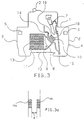
- Figures 1, 2 and 3 are three schematic sectional views, respectively illustrating three particular embodiments of the invention.
- Figures 1a, 2a and 3a are schematic side views, illustrating the shape and the arrangement of the coolers corresponding respectively to FIGS. 1, 2 and 3.
- a pole 1 of miniature circuit breaker comprising an insulating housing B, having on its front face an operating lever 2 and on its two narrow lateral faces 3, 4, connection terminals 5, 6.
- Inside the housing B are housed, as is known per se, a movable contact 7 and a fixed contact 8.
- the movable contact 7 is controlled by a control mechanism (not shown) connecting the aforementioned lever 2 to the contact mobile 7 for contact closure.
- B are also housed a thermal release and electromagnetic release (not shown), susceptible cause, in the event of an overload or short-circuit, an automatic opening of the contacts.
- the lower part of the housing B contains a breaking chamber 9 constituted by a first arc-forming chamber 10, communicating with the entry of a second chamber 11, known as arc extinction, comprising separators 13 constituted by a stack of plates (or sheets) which extend parallel to the base 12 of the housing B.
- the movable contact 7 extends substantially perpendicular to the plane of the plates 13, of so as to draw an arc between the contacts 7, 8, during their separation, the direction of which initial is substantially parallel to the plates 13.
- the aforementioned interrupting chamber 9 is laterally delimited by arc horns 14, 15 respectively connected electrically to the two aforementioned terminals 5, 6. These arc horns 14, 15 are arranged so as to capture the arc pulled between the contacts 7, 8 during their separation.
- circuit breaker As such a circuit breaker is well known to specialists, it will be unnecessary to describe in more detail its arrangement or operation.
- cooling elements 16 are placed around the movable contact 7 and are intended to cool the hot gases present around the movable contact 7 after the switching of the arc.
- These coolers 16 are constituted by two sets 17a, 17b of plates 17 parallel to each other, said assemblies being disposed respectively on either side of the movable contact 7.
- these cooling elements 16, or coolers are constituted by two sets 18a, 18b of tubes 18 parallel to each other, said assemblies 18a, 18b being arranged on either side of the movable contact 7.
- these tubes 18, instead of being arranged around the movable contact 7, are placed in the arc-forming chamber 10, at a certain distance from said contact 7, for example at same distance between the separators 13 and the movable contact 7. It will be noted that in this case, the two sets of tubes 18a, 18b will be separated by a distance a greater than the width of the movable contact 7. In these three embodiments, the large exchange surface of the coolers 16 causes significant cooling of the gas.
Landscapes
- Arc-Extinguishing Devices That Are Switches (AREA)
- Circuit Breakers (AREA)
Description
Dans ces trois réalisations, la surface d'échange importante des refroidisseurs 16 entraíne un refroidissement significatif du gaz.
Claims (10)
- Chambre de coupure d'un disjoncteur électrique comprenant une chambre de formation d'arc renfermant un contact fixe et un contact mobile, lesquels, au moment de leur séparation forment un arc entre eux, ladite chambre de formation communiquant avec l'entrée d'une deuxième chambre dite d'extinction d'arc, caractérisée en ce qu'elle comporte en outre au moins un refroidisseur (16) placé à l'intérieur de la chambre de formation d'arc (10) de manière à refroidir les gaz produits autour du contact mobile (7) sous l'effet de l'évaporation des parois latérales du boítier après la commutation de l'arc.
- Chambre de coupure selon la revendication 1, caractérisée en ce que les refroidisseurs précités (16) sont placés autour du contact mobile (7).
- Chambre de coupure selon la revendication 1, caractérisée en ce que les refroidisseurs précités (16) sont placés entre le contact mobile (7) et la chambre d'extinction précitée (11), à une distance prédéterminée dudit contact mobile (7).
- Chambre de coupure selon l'une quelconque des revendications précédentes, caractérisée en ce que les refroidisseurs précités (16) sont constitués par des plaques (17).
- Chambre de coupure selon l'une quelconque des revendications 1 à 3, caractérisée en ce que les refroidisseurs précités (16) sont constitués par des tubes (18).
- Chambre de coupure selon la revendication 4, caractérisée en ce que les refroidisseurs précités (16) comprennent deux ensembles de plaques (17a, 17b) parallèles entre elles, disposés de part et d'autre du contact mobile (7).
- Chambre de coupure selon la revendication 5, caractérisée en ce que les refroidisseurs précités comprennent deux ensembles de tubes (18a, 18b) parallèles entre eux, disposés de part et d'autre du contact mobile (7).
- Chambre de coupure selon la revendication 6, caractérisée en ce que les plaques précitées (17) s'étendent sensiblement parallèlement au contact mobile (7).
- Chambre de coupure selon la revendication 7, caractérisée en ce que les tubes précités (18) s'étendent sensiblement perpendiculairement au contact mobile (7).
- Chambre de coupure selon l'une quelconque des revendications précédentes, caractérisée en ce que les refroidisseurs précités (16) sont réalisés en métal ou en céramique.
Applications Claiming Priority (2)
| Application Number | Priority Date | Filing Date | Title |
|---|---|---|---|
| FR9414006 | 1994-11-18 | ||
| FR9414006A FR2727240B1 (fr) | 1994-11-18 | 1994-11-18 | Chambre de coupure d'un disjoncteur electrique |
Publications (2)
| Publication Number | Publication Date |
|---|---|
| EP0713232A1 EP0713232A1 (fr) | 1996-05-22 |
| EP0713232B1 true EP0713232B1 (fr) | 1999-07-28 |
Family
ID=9469049
Family Applications (1)
| Application Number | Title | Priority Date | Filing Date |
|---|---|---|---|
| EP19950410128 Expired - Lifetime EP0713232B1 (fr) | 1994-11-18 | 1995-11-10 | Chambre de coupure d'un disjoncteur électrique |
Country Status (4)
| Country | Link |
|---|---|
| EP (1) | EP0713232B1 (fr) |
| DE (1) | DE69511046T2 (fr) |
| ES (1) | ES2135025T3 (fr) |
| FR (1) | FR2727240B1 (fr) |
Families Citing this family (3)
| Publication number | Priority date | Publication date | Assignee | Title |
|---|---|---|---|---|
| DE102007001802B4 (de) * | 2006-12-22 | 2010-02-25 | Abb Ag | Elektrisches Schaltgerät |
| US8164018B2 (en) * | 2009-03-23 | 2012-04-24 | Siemens Industry, Inc. | Circuit breaker arc chambers and methods for operating same |
| DE102017204942B4 (de) * | 2017-03-23 | 2022-01-20 | Siemens Aktiengesellschaft | Elektromechanisches Schutzschaltgerät |
Family Cites Families (4)
| Publication number | Priority date | Publication date | Assignee | Title |
|---|---|---|---|---|
| DE1922747A1 (de) * | 1969-05-03 | 1970-11-05 | Bbc Brown Boveri & Cie | Lichtbogenkammer |
| DE3443122A1 (de) * | 1984-11-27 | 1986-05-28 | Brown, Boveri & Cie Ag, 6800 Mannheim | Vorrichtung zur unterbrechung von stromkreisen |
| FR2575861B1 (fr) * | 1985-01-07 | 1987-01-16 | Merlin Gerin | Disjoncteur electrique miniature a chambre de formation d'arc |
| DE3619241C2 (de) * | 1986-06-07 | 1994-07-21 | Kloeckner Moeller Gmbh | Löscheinrichtung für einen Leitungsschutzschalter |
-
1994
- 1994-11-18 FR FR9414006A patent/FR2727240B1/fr not_active Expired - Fee Related
-
1995
- 1995-11-10 EP EP19950410128 patent/EP0713232B1/fr not_active Expired - Lifetime
- 1995-11-10 ES ES95410128T patent/ES2135025T3/es not_active Expired - Lifetime
- 1995-11-10 DE DE1995611046 patent/DE69511046T2/de not_active Expired - Lifetime
Also Published As
| Publication number | Publication date |
|---|---|
| FR2727240A1 (fr) | 1996-05-24 |
| DE69511046D1 (de) | 1999-09-02 |
| DE69511046T2 (de) | 2000-02-17 |
| FR2727240B1 (fr) | 1996-12-13 |
| EP0713232A1 (fr) | 1996-05-22 |
| ES2135025T3 (es) | 1999-10-16 |
Similar Documents
| Publication | Publication Date | Title |
|---|---|---|
| EP2061051B1 (fr) | Chambre de coupure et disjoncteur équipé d'une telle chambre de coupure | |
| EP0236202B1 (fr) | Appareil de coupure de courant à commutateur statique et disjoncteur de protection | |
| EP1146529B1 (fr) | Pôle pour un disjoncteur électrique limiteur de basse tension de puissance et disjoncteur muni d'un tel pôle | |
| EP0042778B1 (fr) | Disjoncteur miniature unipolaire et neutre | |
| EP0817223A1 (fr) | Dispositif de désionisation des gaz notamment des gaz de coupure dans une chambre d'extinction d'arc d'un disjoncteur basse tension à boítier moulé et chambre d'extinction d'arc équipée de ce dipositif | |
| FR2803686A1 (fr) | Pole pour disjoncteur electrique, muni d'une chambre d'extinction d'arc a ecrans dielectriques | |
| FR3073974A1 (fr) | Disjoncteur multipolaire a basse tension | |
| EP0713232B1 (fr) | Chambre de coupure d'un disjoncteur électrique | |
| EP2804189B1 (fr) | Chambre de coupure pour un appareil de protection électrique et appareil de protection électrique le comportant | |
| EP1667179B1 (fr) | Dispositif électrique de coupure avec recyclage des gaz de coupure | |
| FR2461349A1 (fr) | Chambre de coupure perfectionnee pour disjoncteur basse tension multipolaire a boitier moule | |
| EP0649155B1 (fr) | TÔle de conduction double pour chambre de conduction d'arc de disjoncteur | |
| FR3141796A1 (fr) | Contacteur électrique à recirculation des gaz ionisés | |
| EP3035363B1 (fr) | Chambre de coupure d'arc pour un disjoncteur electrique, et disjoncteur comportant une telle chambre | |
| FR2959347A1 (fr) | Pole de coupure avec deflecteur d'arc et contacteur le comprenant | |
| EP0619592B1 (fr) | Disjoncteur électrique à répulsion électrodynamique des contacts et à chambres de coupure double | |
| EP0148058A2 (fr) | Disjoncteur miniature à tenue diélelectrique améliorée | |
| EP1667180B1 (fr) | Dispositif électrique de coupure avec chambre d'extinction d'arc à ailettes de désionisation | |
| EP1103996B1 (fr) | Dispositif de coupure pour appareil interrupteur | |
| EP1764811A1 (fr) | Dispositif de coupure comportant une chambre d'extinction d'arc de taille réduite | |
| FR2905795A1 (fr) | Dispositif de contact pour appareil electrique et appareil electrique equipe d'un tel dispositif | |
| FR2733352A1 (fr) | Pole pour appareil limiteur de courant | |
| EP0269530B1 (fr) | Chambre de coupure d'un disjoncteur électrique | |
| FR2584230A1 (fr) | Chambre d'extinction d'arc pour disjoncteur a basse tension a coupure dans l'air | |
| EP0646938A1 (fr) | Disjoncteur à chambre d'extinction d'arc perfectionnée |
Legal Events
| Date | Code | Title | Description |
|---|---|---|---|
| PUAI | Public reference made under article 153(3) epc to a published international application that has entered the european phase |
Free format text: ORIGINAL CODE: 0009012 |
|
| AK | Designated contracting states |
Kind code of ref document: A1 Designated state(s): DE ES GB IT |
|
| 17P | Request for examination filed |
Effective date: 19961108 |
|
| 17Q | First examination report despatched |
Effective date: 19970423 |
|
| GRAG | Despatch of communication of intention to grant |
Free format text: ORIGINAL CODE: EPIDOS AGRA |
|
| GRAG | Despatch of communication of intention to grant |
Free format text: ORIGINAL CODE: EPIDOS AGRA |
|
| GRAH | Despatch of communication of intention to grant a patent |
Free format text: ORIGINAL CODE: EPIDOS IGRA |
|
| GRAH | Despatch of communication of intention to grant a patent |
Free format text: ORIGINAL CODE: EPIDOS IGRA |
|
| GRAA | (expected) grant |
Free format text: ORIGINAL CODE: 0009210 |
|
| AK | Designated contracting states |
Kind code of ref document: B1 Designated state(s): DE ES GB IT |
|
| REF | Corresponds to: |
Ref document number: 69511046 Country of ref document: DE Date of ref document: 19990902 |
|
| RAP2 | Party data changed (patent owner data changed or rights of a patent transferred) |
Owner name: SCHNEIDER ELECTRIC INDUSTRIES SA |
|
| REG | Reference to a national code |
Ref country code: ES Ref legal event code: FG2A Ref document number: 2135025 Country of ref document: ES Kind code of ref document: T3 |
|
| ITF | It: translation for a ep patent filed | ||
| GBT | Gb: translation of ep patent filed (gb section 77(6)(a)/1977) |
Effective date: 19991102 |
|
| PLBE | No opposition filed within time limit |
Free format text: ORIGINAL CODE: 0009261 |
|
| STAA | Information on the status of an ep patent application or granted ep patent |
Free format text: STATUS: NO OPPOSITION FILED WITHIN TIME LIMIT |
|
| 26N | No opposition filed | ||
| REG | Reference to a national code |
Ref country code: GB Ref legal event code: IF02 |
|
| REG | Reference to a national code |
Ref country code: DE Ref legal event code: R084 Ref document number: 69511046 Country of ref document: DE Effective date: 20111228 |
|
| PGFP | Annual fee paid to national office [announced via postgrant information from national office to epo] |
Ref country code: DE Payment date: 20121112 Year of fee payment: 18 |
|
| PGFP | Annual fee paid to national office [announced via postgrant information from national office to epo] |
Ref country code: GB Payment date: 20131106 Year of fee payment: 19 |
|
| PGFP | Annual fee paid to national office [announced via postgrant information from national office to epo] |
Ref country code: IT Payment date: 20131114 Year of fee payment: 19 Ref country code: ES Payment date: 20131011 Year of fee payment: 19 |
|
| PG25 | Lapsed in a contracting state [announced via postgrant information from national office to epo] |
Ref country code: DE Free format text: LAPSE BECAUSE OF NON-PAYMENT OF DUE FEES Effective date: 20140603 |
|
| REG | Reference to a national code |
Ref country code: DE Ref legal event code: R119 Ref document number: 69511046 Country of ref document: DE Effective date: 20140603 |
|
| GBPC | Gb: european patent ceased through non-payment of renewal fee |
Effective date: 20141110 |
|
| PG25 | Lapsed in a contracting state [announced via postgrant information from national office to epo] |
Ref country code: GB Free format text: LAPSE BECAUSE OF NON-PAYMENT OF DUE FEES Effective date: 20141110 |
|
| REG | Reference to a national code |
Ref country code: ES Ref legal event code: FD2A Effective date: 20151229 |
|
| PG25 | Lapsed in a contracting state [announced via postgrant information from national office to epo] |
Ref country code: IT Free format text: LAPSE BECAUSE OF NON-PAYMENT OF DUE FEES Effective date: 20141110 |
|
| PG25 | Lapsed in a contracting state [announced via postgrant information from national office to epo] |
Ref country code: ES Free format text: LAPSE BECAUSE OF NON-PAYMENT OF DUE FEES Effective date: 20141111 |