EP0712964B1 - Mixing valve water outlet - Google Patents
Mixing valve water outlet Download PDFInfo
- Publication number
- EP0712964B1 EP0712964B1 EP95117456A EP95117456A EP0712964B1 EP 0712964 B1 EP0712964 B1 EP 0712964B1 EP 95117456 A EP95117456 A EP 95117456A EP 95117456 A EP95117456 A EP 95117456A EP 0712964 B1 EP0712964 B1 EP 0712964B1
- Authority
- EP
- European Patent Office
- Prior art keywords
- accordance
- carrier
- pipe
- water outlet
- pipe section
- Prior art date
- Legal status (The legal status is an assumption and is not a legal conclusion. Google has not performed a legal analysis and makes no representation as to the accuracy of the status listed.)
- Expired - Lifetime
Links
- XLYOFNOQVPJJNP-UHFFFAOYSA-N water Substances O XLYOFNOQVPJJNP-UHFFFAOYSA-N 0.000 title claims abstract description 101
- 230000001681 protective effect Effects 0.000 claims description 15
- 125000006850 spacer group Chemical group 0.000 claims description 9
- 230000007704 transition Effects 0.000 claims description 3
- 238000006073 displacement reaction Methods 0.000 claims description 2
- 230000002093 peripheral effect Effects 0.000 claims description 2
- 230000003014 reinforcing effect Effects 0.000 claims description 2
- 230000000284 resting effect Effects 0.000 claims description 2
- 230000003319 supportive effect Effects 0.000 claims 2
- 239000007788 liquid Substances 0.000 description 5
- 238000004519 manufacturing process Methods 0.000 description 5
- 239000008399 tap water Substances 0.000 description 4
- 235000020679 tap water Nutrition 0.000 description 4
- 238000009434 installation Methods 0.000 description 3
- 244000089486 Phragmites australis subsp australis Species 0.000 description 2
- 238000010276 construction Methods 0.000 description 2
- 230000000694 effects Effects 0.000 description 2
- 230000004048 modification Effects 0.000 description 2
- 238000012986 modification Methods 0.000 description 2
- 241001295925 Gegenes Species 0.000 description 1
- 210000001015 abdomen Anatomy 0.000 description 1
- 238000005452 bending Methods 0.000 description 1
- 239000013013 elastic material Substances 0.000 description 1
- 238000003780 insertion Methods 0.000 description 1
- 230000037431 insertion Effects 0.000 description 1
- 230000002452 interceptive effect Effects 0.000 description 1
- 230000036316 preload Effects 0.000 description 1
- 238000007789 sealing Methods 0.000 description 1
- 239000007787 solid Substances 0.000 description 1
- 239000007921 spray Substances 0.000 description 1
- 229910001220 stainless steel Inorganic materials 0.000 description 1
- 239000010935 stainless steel Substances 0.000 description 1
- 238000003466 welding Methods 0.000 description 1
Images



Classifications
-
- E—FIXED CONSTRUCTIONS
- E03—WATER SUPPLY; SEWERAGE
- E03C—DOMESTIC PLUMBING INSTALLATIONS FOR FRESH WATER OR WASTE WATER; SINKS
- E03C1/00—Domestic plumbing installations for fresh water or waste water; Sinks
- E03C1/02—Plumbing installations for fresh water
- E03C1/04—Water-basin installations specially adapted to wash-basins or baths
- E03C1/0404—Constructional or functional features of the spout
-
- E—FIXED CONSTRUCTIONS
- E03—WATER SUPPLY; SEWERAGE
- E03C—DOMESTIC PLUMBING INSTALLATIONS FOR FRESH WATER OR WASTE WATER; SINKS
- E03C1/00—Domestic plumbing installations for fresh water or waste water; Sinks
- E03C1/02—Plumbing installations for fresh water
- E03C1/04—Water-basin installations specially adapted to wash-basins or baths
- E03C2001/0417—Water-basin installations specially adapted to wash-basins or baths having space-saving features, e.g. retractable, demountable
Definitions
- mixer taps e.g. B. for kitchen sinks
- an approximately circular cylindrical housing which with a vertical housing axis in an opening of a Sink, a sink or a built-in sink or a basin-receiving table or cover plate mounted a mixer valve cartridge or cartridge and above a mostly lever-like, tiltable and swiveling control element for the mixing valve cartridge;
- a crane-like water outlet branches off from the housing a crane-like water outlet, the be pivoted together with a housing part around the cylinder axis can.
- Mixer taps with one by one are also known vertical axis swiveling, crane - like water outlet and two separate and also attachable, each water valves with a control element for cold and hot water.
- Known mixer tap water outlet devices of the first type are, although most widely used, often called perceived as annoying because it is over the carrier (be it a Sink, a built-in sink or the cover plate of a base cabinet a fitted kitchen, a bathroom fixture or the like) protrude considerably upward and therefore not only when handling in the area of Interfering with the water outlet device (many items of crockery was by striking such a water outlet device damaged or even destroyed), but e.g. Belly then be perceived as annoying when on the sink, the Cover plate or the like placed larger objects should be. It can also be such a known water outlet device make impossible one behind it Open the window fully, d. H. this window or one Swing the window sash all the way open, namely whenever the parapet is not at a level above the highest point of the water outlet device; just behind a sink you would often like to be in a kitchen to place a window.
- FR-A-990 965 is now a water outlet device which emerges via a multi-part straight guide tube has that with a vertical axis in an opening of a Table, cover or worktop mounted and so on can be specified that the guide tube this plate relatively slightly towered over.
- the guide tube there is a straight water pipe whose outer diameter is significantly smaller than the inside diameter of the guide tube; this with the latter coaxial water pipe is on upper end of the guide tube in the axial direction and kept sealed and guided, and at the top, open end of the water pipe is a crane-like water outlet attached, which slants at an angle of approx. 40 ° protrudes above.
- Embodiment of the known water outlet device mitigates the problems described above are eliminated but not for two reasons: the means, which of the rotatable bearing and the sliding guide of the extendable Water pipe and the seal between it and serve the stationary guide tube, build over the Plate in which the water outlet device is installed, relatively high, and also the crane-like protrudes Water outlet obliquely upwards, so that even when completely lowered water pipe the highest point of the water outlet is a considerable distance above the plate.
- the invention was based on the object, the above in Connection with other known mixer tap water discharge devices problems described better, d. H. complete, to solve than this according to the water outlet facilities the FR-A-990 965 assets.
- Valve unit forms a separate part and in side Distance from the movable parts of the water outlet device can be mounted, it allows the invention Construction, the vertically movable straight Pipe area including the pipe end area in a non-use position lower, in which the pipe end area together with the the mouthpiece provided with a whole small distance from the top of the plate-like carrier has, whereby itself in this position thanks to the the flexible hose pullable out of the pipe end area and with the mouthpiece provided with the water outlet opening the water outlet device according to the invention is still relatively can work without restrictions.
- a plate-like carrier When a plate-like carrier is mentioned above, of course, this also includes an area of a sink or Built-in sink, a built-in basin, such as a washbasin, or the like, which is at least approximately has horizontal top.
- the water outlet opening Level of the top of the carrier is immediately adjacent, so this also includes cases in which the Area of the water outlet device comprising the water outlet opening is slightly below this level - if it is Pipe area z. B. at a so-called battery bank Sink is arranged in the lower position with the area of the water outlet device provided with the water outlet opening also something in a neighboring of the battery bank Protrude into the sink. Also with the water outlet opening provided area of the water outlet device lie on top of the sink, e.g. B. on the top the mentioned battery bank.
- the guide could take the form of a flat surface, one vertically extending rib or the like to have; However, embodiments are preferred in which the guide includes the straight tube area all around all with regard to the desired rotatability of the straight Pipe area around its axis.
- the guide also with one on the outer circumference of the straight Provide the tube area around the elastic seal which not only prevent that between Guide and the pipe area water, other liquids or Dirt can get down, but with such a elastic seal can also be achieved that the water outlet device located in its upper position of use, if you let them go, either not at all or only sinks slowly and not to its lower position falls down.
- embodiments are preferred in which the Water outlet device by a locking device in is held in its upper position of use, d. H. Embodiments, where to hold the straight pipe section in its upper position provided a locking device and this is designed such that the straight tube area can be lowered manually into its lower position.
- This locking device could e.g. B. as a manually overcome spring locking device be designed, easier to manufacture and
- the backdrop then only has to be designed in such a way that it all wants Allows movement of the straight pipe area. Even though the backdrop provided on the straight tube area and the locking member could be arranged stationary, arise Manufacturing and assembly advantages when the backdrop on the Guide provided and the locking member firmly with the straight Pipe area is connected.
- the design of the Backdrop any desired movement of the straight tube area and to allow the water outlet opening.
- the water outlet device is geometrically adequate simply designed and therefore easy and cheap producible backdrop that the shape of a groove or one Slot with an upper, approximately horizontal first backdrop area, an approximately vertical second backdrop area and a lower one, again roughly horizontally extending third backdrop area, the Locking member designed as a projection engaging in the backdrop is.
- the exact water outlet device in their upper or in their lower Position at z. B. pivot 90 ° or 180 °, and the length the approximately vertical second backdrop area determines the stroke of the water outlet device.
- the Backdrop z. B. may have the shape of a lying H, is sufficient a simpler shape similar for all requirements a lying U.
- the upper, first backdrop area is a hump forms, which cooperates with the backdrop Head start by lifting and turning the straight tube area must be run over before the projection in the vertical second backdrop area can be brought.
- the hump is conveniently located at the transition from the first to the second backdrop area.
- the straight pipe area is multi-part and one straight lower tube and a detachably connected to it, especially screwed, upper tube is formed.
- the actual water outlet device projects least above the level of the top of the carrier, if slidable in the approximately vertical direction straight pipe section above an approximately horizontal extending pipe area connects, even if to the Place the latter z. B. a slightly bent pipe area could kick.
- the straight pipe area and the approximate horizontally extending pipe area could be forming meet at a right angle in particular, for production, however, it is easier if between the straight pipe area and the horizontal pipe area Pipe bend with a relatively small radius of curvature, since then the two pipe areas are easily formed have a single piece of pipe made by bending and z. B. welding work can be avoided.
- a protective and stiffening tube is attached, which not just dirt from outside Backdrop prevents, but also the qualities of leadership improved for the vertically displaceable, straight pipe area and excludes that the actual water outlet device in its upper position of use to the side and can be moved around.
- the guide tube and that Protection and stiffening pipe not with tight tolerances very much need to be manufactured precisely will be another improvement achieved in that between the guide tube and the Protection tube at least two elastic snap ring-like ring elements be arranged at an axial distance from one another, each of which from the protective tube in the radial direction against the Guide tube is pressed. Then at least expediently above and below the backdrop, even better at the top and at the such a ring element at the lower end of the protective tube arranged to close the gap between the two pipes at his to seal the upper and lower ends.
- the carrier holding the valve unit can act about the same that the parts that can be raised and lowered are provided, or else another carrier, for example around a built-in sink receiving cover plate or - which is to be preferred - um a second battery bank of the built-in sink.
- a built-in sink receiving cover plate or - which is to be preferred - um a second battery bank of the built-in sink can be inventively easily design the valve unit so that it is in a standardized, circular fitting installation opening of built-in sinks, which has a diameter of 35 mm, preferably insert from below and then fasten.
- Thickness dimension in the direction perpendicular to the plate-like Carrier
- the cap is the nut or possibly the collar spreads as far as possible to prevent the ingress of Liquids and other dirt from above into the valve unit to prevent as much as possible, but without the Hinder or limit the tilting movement of the control pin, it is easiest that in constructions where the control pin from a rest position in which the mixing valve cartridge is closed and the control pin is approximately vertical runs into an inclined position in which the mixing valve cartridge is fully open, the cap can be tilted is designed so that an overlapping the mother or the collar Circumferential area of the cap on the inclination assigned side shorter (in the direction of the control pin axis measured) than on the opposite side, and so short that the cap prevents the tilting movement of the control pin not limited.
- FIG. 1 shows a carrier plate 10, namely in one Section along a vertical plane, which before the invention Water outlet device is so that one of the latter penetrated opening in the form of a circular Hole in the carrier plate is not recognizable.
- a guide tube 12 is inserted from above, which has at its upper end a collar 14, the Outside diameter is larger than the opening in the carrier plate 10 and which rests on the latter.
- Below the Ring collar 14, the guide tube 12 has an external thread 16, on which a fastening nut 18 is screwed with whose help the support plate 10 between the collar 14 and the mounting nut 18 can be clamped.
- On the A protective tube 20 is pushed onto the guide tube 12 from below and kept in a manner to be explained later.
- FIG. 1 One along a vertical, i.e. H. perpendicular to the carrier plate 10 extending tube axis 22 in the guide tube 12 slidably and water discharge crane held pivotable about this axis 24 has, as far as this can be seen in FIG. 1, an approximately inverted L-shaped upper tube 26 with a vertical pipe section 28, a pipe bend 30 and a horizontal pipe section 32, in which according to FIG. 1 right end one with a downward water outlet opening 34 provided mouthpiece 36 is inserted, so that it is from the pipe section 32 of FIG. 1 to the right can be pulled out.
- This mouthpiece 36 forms a hose shower, and that formed by the leaking water shower spray was designated 40.
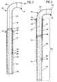
- Figures 3 and 4 show that the vertical pipe section 28 of the upper tube 26 with the lower tube 44 is connected by a screw 46 and as a straight pipe section 48, which is composed of the lower pipe 44 is formed with the vertical tube section 28 in the guide tube 12 is guided and held, namely so that the unit formed by the two tubes 26 and 44 in the direction the tube axis 22 is slidable and rotatable about this axis - In cross section is both the inner contour of the guide tube 12 as well as the outer contour of the straight tube area 48 circular.
- an elastic sealing ring 50 is arranged, which under lighter Preload against the outer circumference of the straight pipe area 48 is present and not just the annular gap between the guide tube 12 and straight pipe area 48 seals, but also leads to that of the two tubes 26 and 44th unit formed from its upper one, in FIGS. 1 and 3 shown position of use not freely in their in the figures 2 and 4 shown lower position can fall, but slowly slides down when this is in her unit in the upper position of use is released and a locking device to be described later is ineffective.
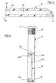
- the mouthpiece 36 shown in FIG. 5 has one on its outer circumference stepped, as shown in FIG. 5 left end region 62 with a circular cylindrical ring surface 64 and one External thread 66; 5 shows the diameter of the ring surface 64 is smaller than the outer diameter of the mouthpiece 36 to the right of the end region 62, and the external thread 66 has an outer diameter, which in turn is smaller than the diameter of the ring surface 64.
- the end portion is 62 into the right end of the horizontal according to FIGS. 1 to 4 Pipe section 32 insertable; for this purpose the the latter a circular cylindrical fit 68, the inside diameter corresponds to the outer diameter of the ring surface 64.
- the backdrop 56 is formed Slot in the guide tube 12 from an upper, horizontal extending first slot region 56a, one extending vertically second slot area 56b and a lower one, likewise horizontally extending third slot area 56c, which together form a backdrop with the shape of a lying U form.
- the horizontal upper slot area 56a forms a bump 56d, the slot forming the backdrop 56 being everywhere, however has a slot width that is the same or very slight is larger than the outer diameter of the grub screw 58.
- the upper horizontal slot area 56a (including hump 56d) and the lower horizontal slot area 56c extend each over a circumferential angle of the guide tube 12, which is freely selectable and for example a little more than 90 ° or a little more than 180 ° around the water outlet crane 24 (taking into account the diameter of the grub screw 58) pivot around the pipe axis 22 by 90 ° or 180 ° to be able (the left ends of the two Slot areas 56a and 56c cannot be seen in the drawing).
- FIGS. 1 and 2 Protection tube 20 shows that shown in FIGS. 1 and 2 Protection tube 20 in a longitudinal section.
- each of the two ring grooves 52 and 54 can be in the Figures 9A and 9B shown snap ring-like ring element 74 insert from an elastic material; this has three projections 74a on its inner circumference, which then engage in the elongated holes 52a and 54a and twist prevent the ring elements 74 with respect to the guide tube 12.
- the diameter of the bottom of the annular groove 52 or 54, the inner diameter of the protective tube 20, the outer diameter the ring elements 74 and their inner diameter between the Projections 74a are now coordinated with one another such that after the protective tube 20 over the guide tube 12 and the two ring elements 74 has been pushed, the protective tube 20 about the ring elements 74, the guide tube 12 in a radial Compresses direction; also prevents the lower ring element 74 that dirt from below in the annular gap between the protective tube 20 and the guide tube 12 and thus in the Area of the backdrop 56 can penetrate.
- the ring members 74 are attached to the guide tube 12 so that their gaps 74b - viewed in the direction of the tube axis 22 - not in the area of the backdrop 56.
- the length of the protective tube 20 must therefore be at least the axial distance between the two Annular grooves 52 and 54 correspond to each other and is preferred slightly larger than this distance.
- the water discharge crane 24 is in its upper position of use or always in its lower position locks when the grub screw 58 in the upper slot area 56a to the left (according to FIG. 6) of the hump 56d or in the lower one Slot area 56c to the left of the vertical slot area 56b is located.
- the water discharge crane 24 is in its upper Use position, the grub screw 58 can either by slightly lifting and slightly pivoting the Water discharge crane 24 lifted over the hump 56d and over the vertical slot area 56b, thanks the rounded flank of the bump 56d as shown in FIG. 6 the latter can also be done simply by swiveling the Overcome water outlet crane 24 because doing so the left flank of the hump 56d automatically causes the water discharge crane is raised slightly.
- FIGS. 10A and 10B show a carrier plate 10 'in which it is the carrier plate shown in Figures 1 and 2 10, but can also be a different carrier plate.
- the carrier plate 10 ' has a particularly circular opening 100, in which a valve unit designated as a whole by 102 is attached.
- This includes a pot-shaped housing 104, a commercial mixing valve cartridge accommodated by the latter 106 with a control pin 108 for actuation the mixing valve cartridge, a nut 110 and an operating element 112 with a handle 114 for actuating the valve unit 102.
- the housing 104 has a lower housing part 104a and an upper housing part 104b, which after the insertion of the Mixing valve cartridge 106 in the lower housing part via a Screw connection 104c are connected to one another.
- the upper housing part 104b has a collar 104d which defines the opening 104 reaches through and on which by means of a screw connection 104e Nut 110 can be attached.
- the collar 104d has an outer diameter which corresponds to that Diameter of the opening 100 corresponds, so that the valve unit Do not move 102 in the carrier plate 10 ' can, and thus the upper housing part 104b from below into the Opening 100 can be used, the outer diameter of the collar 104d in the area of the screw connection 104e in no way be larger than the diameter of this opening.
- the thickness of the carrier plate 10 ' take into account (in the case of a thicker carrier plate, a less thick spacer 120 used and vice versa), so that guaranteed by choosing an appropriate spacer ring can be that the valve unit 102 is always the same distance protrudes upward over the top of the carrier plate 10 '.
- Mixing valve cartridges of the type in question can be Operate in the following way: By tilting the control pin 108 from its vertical position shown in Fig. 10A in the oblique position shown in Fig. 10B, the Mixing valve cartridge completely in the course of the tilting movement open - it is in the vertical position of the control pin completely closed - and by turning the control pin 108 its pin axis 108a can be any mixing ratio between cold water and hot water.
- the backdrop 56 is approximately C-shaped; with it and the same water outlet device e.g. with built-in sinks can be combined, one of which is a Sink to the right of the installation point for the water outlet device and the others left of this place the tube area corresponding to the straight tube area 48 a modified embodiment is not just about about 90 °, but pivotable about 180 °, it would be advantageous if this pipe area in could be lowered in both pivoting end positions. This can be achieved in a simple manner in that the Backdrop - of course in a developed form - roughly that Has the shape of a rectangle.
- the backdrop is in the outer guide 12 provided that with the backdrop cooperating locking member 58 on the pivotable and height-adjustable straight tube area 48.
- modification of the device according to the invention is the backdrop in the outer circumference of the straight tube area incorporated and the locking member attached to the guide.
- Such embodiments are preferred this variant, which three such spring-loaded locking elements possess that at equal angular distances from each other are distributed so as to bring about a centering effect.
Landscapes
- Health & Medical Sciences (AREA)
- Life Sciences & Earth Sciences (AREA)
- Engineering & Computer Science (AREA)
- Hydrology & Water Resources (AREA)
- Public Health (AREA)
- Water Supply & Treatment (AREA)
- Domestic Plumbing Installations (AREA)
- Filling, Topping-Up Batteries (AREA)
Abstract
Description
Herkömmliche sogenannte Mischbatterien, z. B. für Küchenspülen, haben häufig ein ungefähr kreiszylindrisches Gehäuse, welches mit vertikaler Gehäuseachse in einer Öffnung einer Spüle, eines Waschbeckens oder einer eine Einbauspüle oder ein Becken aufnehmenden Tisch- oder Abdeckplatte montiert wird, eine Mischventilpatrone oder -kartusche aufnimmt und oben ein meist hebelartiges, kipp- und schwenkbares Bedienungselement für die Mischventilpatrone trägt; außerdem zweigt von dem Gehäuse ein kranartiger Wasserauslaß ab, der samt einem Gehäuseteil um die Zylinderachse geschwenkt werden kann. Bekannt sind aber auch Mischbatterien mit einem um eine vertikale Achse schwenkbaren, kranartigen Wasserauslaß und zwei hiervon getrennten und auch getrennt anbringbaren, jeweils mit einem Bedienungselement versehbaren Wasserventilen für Kalt- und Warmwasser. Conventional so-called mixer taps, e.g. B. for kitchen sinks, often have an approximately circular cylindrical housing, which with a vertical housing axis in an opening of a Sink, a sink or a built-in sink or a basin-receiving table or cover plate mounted a mixer valve cartridge or cartridge and above a mostly lever-like, tiltable and swiveling control element for the mixing valve cartridge; Moreover branches off from the housing a crane-like water outlet, the be pivoted together with a housing part around the cylinder axis can. Mixer taps with one by one are also known vertical axis swiveling, crane - like water outlet and two separate and also attachable, each water valves with a control element for cold and hot water.
Bekannte Mischbatterie-Wasserauslaufeinrichtungen der erstgenannten Art werden, obwohl sie am weitesten verbreitet sind, häufig als störend empfunden, da sie über den Träger (sei es nun eine Spüle, eine Einbauspüle oder die Abdeckplatte eines Unterbauschranks einer Einbauküche, eines Badezimmereinrichtungsgegenstands oder dergleichen) beträchtlich nach oben hinausragen und deshalb nicht nur beim Hantieren im Bereich der Wasserauslaufeinrichtung stören (schon so manches Geschirrteil wurde durch Anschlagen an eine solche Wasserauslaufeinrichtung beschädigt oder gar zerstört), sondern z. B. auch dann als störend empfunden werden, wenn auf der Spüle, der Abdeckplatte oder dergleichen größere Gegenstände abgelegt werden sollen. Auch kann es eine solche bekannte Wasserauslaufeinrichtung unmöglich machen, ein hinter ihr befindliches Fenster ganz zu öffnen, d. h. dieses Fenster oder einen Fensterflügel ganz aufzuschwenken, nämlich immer dann, wenn die Fensterbrüstung sich nicht auf einem Niveau über der höchsten Stelle der Wasserauslaufeinrichtung befindet; gerade hinter einer Spüle würde man in einer Küche aber oft gerne ein Fenster plazieren. Known mixer tap water outlet devices of the first type are, although most widely used, often called perceived as annoying because it is over the carrier (be it a Sink, a built-in sink or the cover plate of a base cabinet a fitted kitchen, a bathroom fixture or the like) protrude considerably upward and therefore not only when handling in the area of Interfering with the water outlet device (many items of crockery was by striking such a water outlet device damaged or even destroyed), but e.g. Belly then be perceived as annoying when on the sink, the Cover plate or the like placed larger objects should be. It can also be such a known water outlet device make impossible one behind it Open the window fully, d. H. this window or one Swing the window sash all the way open, namely whenever the parapet is not at a level above the highest point of the water outlet device; just behind a sink you would often like to be in a kitchen to place a window.
Aus der FR-A-990 965 geht nun eine Wasserauslaufeinrichtung hervor, welche über ein mehrteiliges gerades Führungsrohr verfügt, das mit vertikaler Achse in einer Öffnung einer Tisch-, Abdeck- oder Arbeitsplatte montiert und an dieser so festgelegt werden kann, daß das Führungsrohr diese Platte verhältnismäßig geringfügig überragt. In dem Führungsrohr befindet sich ein gerades Wasserrohr, dessen Außendurchmesser wesentlich kleiner ist als der Innendurchmesser des Führungsrohrs; dieses mit letzterem koaxiale Wasserrohr ist am oberen Ende des Führungsrohrs in axialer Richtung verschiebbar und abgedichtet gehalten und geführt, und am oberen, offenen Ende des Wasserrohrs ist ein kranartiger Wasserauslaß befestigt, welcher unter einem Winkel von ca. 40° schräg nach oben ragt. In seiner unteren Stellung endet das unten offene Wasserrohr kurz über dem unteren Ende des unten verschlossenen Führungsrohrs, an dessen Mantel eine Kalt- und eine Warmwasserleitung angeschlossen sind, so daß Wasser zwischen dem verschiebbaren Wasserrohr und dem Führungsrohr zum offenen unteren Ende des Wasserrohrs und dann in diesem nach oben zu dem kranartigen Wasserauslaß strömen kann. Diese Ausführungsform der bekannten Wasserauslaufeinrichtung mildert zwar die vorstehend geschilderten Probleme, beseitigt sie jedoch nicht, und zwar aus zwei Gründen: Die Mittel, welche der drehbaren Lagerung sowie der Gleitführung des ausziehbaren Wasserrohrs sowie der Abdichtung zwischen diesem und dem stationären Führungsrohr dienen, bauen über der Platte, in die die Wasserauslaufeinrichtung eingebaut ist, verhältnismäßig hoch, und außerdem ragt der kranartigte Wasserauslaß schräg nach oben, so daß selbst bei vollständig abgesenktem Wasserrohr die höchste Stelle des Wasserauslasses sich in einem erheblichen Abstand über der Platte befindet.FR-A-990 965 is now a water outlet device which emerges via a multi-part straight guide tube has that with a vertical axis in an opening of a Table, cover or worktop mounted and so on can be specified that the guide tube this plate relatively slightly towered over. In the guide tube there is a straight water pipe whose outer diameter is significantly smaller than the inside diameter of the guide tube; this with the latter coaxial water pipe is on upper end of the guide tube in the axial direction and kept sealed and guided, and at the top, open end of the water pipe is a crane-like water outlet attached, which slants at an angle of approx. 40 ° protrudes above. In its lower position, the one open at the bottom ends Water pipe just above the bottom of the bottom closed guide tube, on the jacket of a cold and a hot water pipe is connected so that water between the sliding water pipe and the guide pipe to the open lower end of the water pipe and then in this can flow up to the crane-like water outlet. This Embodiment of the known water outlet device mitigates the problems described above are eliminated but not for two reasons: the means, which of the rotatable bearing and the sliding guide of the extendable Water pipe and the seal between it and serve the stationary guide tube, build over the Plate in which the water outlet device is installed, relatively high, and also the crane-like protrudes Water outlet obliquely upwards, so that even when completely lowered water pipe the highest point of the water outlet is a considerable distance above the plate.
Bei einer sich aus der FR-A-990 965 ergebenden, gegenüber der vorstehend beschriebenen Wasserauslaufeinrichtung modifizierten Ausführungsform ist in den oberen Endbereich des stationären Führungsrohrs ein Wasserauslaßventil integriert, so daß selbst bei vollständig abgesenktem ausziehbarem Wasserrohr der kranartige Wasserauslaß einen noch größeren Abstand von der die Wasserauslaufeinrichtung haltenden Platte aufweist als bei der zunächst beschriebenen ersten Ausführungsform, und zwar obwohl bei dieser Variante der kranartige Wasserauslaß nur unter einem verhältnismäßig kleinen Winkel von ca. 10° schräg nach oben ragt.With a resulting from the FR-A-990 965, opposite the Modified water outlet device described above Embodiment is in the upper end of the stationary Guide tube integrated a water outlet valve, so that even with the retractable water pipe completely lowered the crane-like water outlet an even greater distance from of the plate holding the water outlet device than in the first embodiment described first, and although in this variant the crane-like water outlet only at a relatively small angle of approx. 10 ° upwards.
Der Erfindung lag nun die Aufgabe zugrunde, die vorstehend in Verbindung mit anderen bekannten Mischbatterie-Wasserauslaufeinrichtungen geschilderten Probleme besser, d. h. vollständiger, zu lösen als dies die Wasserauslaufeinrichtungen gemäß der FR-A-990 965 vermögen.The invention was based on the object, the above in Connection with other known mixer tap water discharge devices problems described better, d. H. complete, to solve than this according to the water outlet facilities the FR-A-990 965 assets.
Zur Lösung dieser Aufgabe wird von einer Wasserauslaufeinrichtung gemäß der FR-A-990 965 ausgegangen, d. h. von einer Wasserauslaufeinrichtung mit den Merkmalen des Oberbegriffs des beigefügten Anspruchs 1, und erfindungsgemäß wird eine solche Wasserauslaufeinrichtung entsprechend dem Kennzeichen des Anspruchs 1 gestaltet. To solve this problem, a water outlet device in accordance with FR-A-990 965, d. H. from one Water outlet device with the features of the generic term of appended claim 1, and according to the invention one such water outlet device according to the license plate of claim 1 designed.
Da bei der erfindungsgemäßen Wasserauslaufeinrichtung die Ventileinheit ein separates Teil bildet und in seitlichem Abstand von den verschiebbaren Teilen der Wasserauslaufeinrichtung montiert werden kann, erlaubt es die erfindungsgemäße Konstruktion, den vertikal verschiebbaren geraden Rohrbereich samt Rohrendbereich in eine Nicht-Gebrauchsstellung abzusenken, in der der Rohrendbereich samt dem mit der Wasserauslaßöffnung versehenen Mundstück einen ganz geringen Abstand von der Oberseite des plattenartigen Trägers aufweist, wobei sich selbst in dieser Stellung Dank des aus dem Rohrendbereich herausziehbaren flexiblen Schlauchs und dessen mit der Wasserauslaßöffnung versehenen Mundstücks mit der erfindungsgemäßen Wasserauslaufeinrichtung noch verhältnismäßig uneingeschränkt arbeiten läßt. Since in the water outlet device according to the invention Valve unit forms a separate part and in side Distance from the movable parts of the water outlet device can be mounted, it allows the invention Construction, the vertically movable straight Pipe area including the pipe end area in a non-use position lower, in which the pipe end area together with the the mouthpiece provided with a whole small distance from the top of the plate-like carrier has, whereby itself in this position thanks to the the flexible hose pullable out of the pipe end area and with the mouthpiece provided with the water outlet opening the water outlet device according to the invention is still relatively can work without restrictions.
Wenn vorstehend von einem plattenartigen Träger die Rede ist, so ist hierunter natürlich auch ein Bereich einer Spüle bzw. Einbauspüle, eines Einbaubeckens, wie eines Waschbeckens, oder dergleichen zu verstehen, welcher eine mindestens ungefähr horizontale Oberseite besitzt.When a plate-like carrier is mentioned above, of course, this also includes an area of a sink or Built-in sink, a built-in basin, such as a washbasin, or the like, which is at least approximately has horizontal top.
An die Stelle eines einzigen Wasserschlauchs können auch zwei derartige Leitungen (eine für Kalt- und eine für Warmwasser) treten, welche in dem geraden Rohrbereich verlaufen. Instead of a single water hose, too two such lines (one for cold and one for hot water) which occur in the straight pipe area run.
Wenn vorstehend davon die Rede ist, daß in der unteren Stellung des geraden Rohrbereichs die Wasserauslaßöffnung dem Niveau der Trägeroberseite unmittelbar benachbart ist, so sind hierunter auch Fälle zu verstehen, bei denen der die Wasserauslaßöffnung umfassende Bereich der Wasserauslaufeinrichtung etwas unter diesem Niveau liegt - wenn der gerade Rohrbereich z. B. an einer sogenannten Batteriebank einer Spüle angeordnet ist, kann in seiner unteren Stellung der mit der Wasserauslaßöffnung versehene Bereich der Wasserauslaufeinrichtung auch etwas in ein der Batteriebank benachbartes Becken der Spüle hineinragen. Auch kann der mit der Wasserauslauföffnung versehene Bereich der Wasserauslaufeinrichtung auf der Oberseite der Spüle aufliegen, z. B. auf der Oberseite der erwähnten Batteriebank.If the above is said to be in the lower position of the straight pipe area the water outlet opening Level of the top of the carrier is immediately adjacent, so this also includes cases in which the Area of the water outlet device comprising the water outlet opening is slightly below this level - if it is Pipe area z. B. at a so-called battery bank Sink is arranged in the lower position with the area of the water outlet device provided with the water outlet opening also something in a neighboring of the battery bank Protrude into the sink. Also with the water outlet opening provided area of the water outlet device lie on top of the sink, e.g. B. on the top the mentioned battery bank.
Damit die Wasserauslaßöffnung zumindest in der oberen Gebrauchsstellung der Wasserauslaufeinrichtung über verschiedene Stellen der Umgebung der letzteren gebracht werden kann, empfiehlt es sich, den geraden Rohrbereich und seine Führung so zu gestalten, daß der Rohrbereich in der Führung um seine Rohrachse drehbar ist.So that the water outlet opening at least in the upper position of use the water outlet device via various Places around the latter can be brought it is recommended to use the straight pipe area and its guidance to be designed so that the pipe area in the guide around its Pipe axis is rotatable.
Wenn der gerade Rohrbereich an irgendeiner Stelle seines Außenumfangs (im Querschnitt) von der Kreisform abweicht, könnte die Führung die Gestalt einer ebenen Fläche, einer sich in vertikaler Richtung erstreckenden Rippe oder dergleichen haben; bevorzugt werden jedoch Ausführungsformen, bei denen die Führung den geraden Rohrbereich ringsum umfaßt, vor allem auch im Hinblick auf die gewünschte Drehbarkeit des geraden Rohrbereichs um seine Achse. Bei einer den Rohrbereich umfassenden Führung kann, wie dies besonders zu bevorzugen ist, die Führung auch mit einer am Außenumfang des geraden Rohrbereichs ringsum anliegenden elastischen Dichtung versehen werden, durch die nicht nur verhindert wird, daß zwischen Führung und dem Rohrbereich Wasser, andere Flüssigkeiten oder Schmutz nach unten gelangen können, sondern mit einer solchen elastischen Dichtung läßt sich auch erreichen, daß sich die in ihrer oberen Gebrauchsstellung befindliche Wasserauslaufeinrichtung, wenn man sie losläßt, entweder überhaupt nicht oder nur langsam absinkt und nicht etwa in ihre untere Stellung hinunterfällt.If the straight pipe area at any point on his Outer circumference (in cross section) deviates from the circular shape, the guide could take the form of a flat surface, one vertically extending rib or the like to have; However, embodiments are preferred in which the guide includes the straight tube area all around all with regard to the desired rotatability of the straight Pipe area around its axis. At one the pipe area Comprehensive leadership may particularly like this is, the guide also with one on the outer circumference of the straight Provide the tube area around the elastic seal which not only prevent that between Guide and the pipe area water, other liquids or Dirt can get down, but with such a elastic seal can also be achieved that the water outlet device located in its upper position of use, if you let them go, either not at all or only sinks slowly and not to its lower position falls down.
Bevorzugt werden jedoch Ausführungsformen, bei denen die Wasserauslaufeinrichtung durch eine Arretiervorrichtung in ihrer oberen Gebrauchsstellung gehalten wird, d. h. Ausführungsformen, bei denen zum Halten des geraden Rohrbereichs in dessen oberer Stellung eine Arretiervorrichtung vorgesehen und diese derart ausgebildet ist, daß der gerade Rohrbereich manuell in seine untere Stellung absenkbar ist. Diese Arretiervorrichtung könnte z. B. als manuell überwindbare Federrastvorrichtung gestaltet sein, einfacher herstellbar und bedienungsfreundlicher ist jedoch eine Konstruktion, bei der die Arretiervorrichtung eine Kulisse sowie ein mit dieser zusammenwirkendes Arretierglied umfaßt, von denen das eine Element bezüglich des Trägers und das andere Element bezüglich des geraden Rohrbereichs fest anbringbar ist. Die Kulisse muß dann nur so gestaltet werden, daß sie alle erwünschten Bewegungen des geraden Rohrbereichs zuläßt. Obwohl die Kulisse am geraden Rohrbereich vorgesehen und das Arretierglied stationär angeordnet werden könnte, ergeben sich Fertigungs- und Montagevorteile dann, wenn die Kulisse an der Führung vorgesehen und das Arretierglied fest mit dem geraden Rohrbereich verbunden ist.However, embodiments are preferred in which the Water outlet device by a locking device in is held in its upper position of use, d. H. Embodiments, where to hold the straight pipe section in its upper position provided a locking device and this is designed such that the straight tube area can be lowered manually into its lower position. This locking device could e.g. B. as a manually overcome spring locking device be designed, easier to manufacture and However, a design in which the locking device a backdrop and one with this cooperating locking member, one of which Element regarding the carrier and the other element regarding of the straight pipe area is firmly attachable. The The backdrop then only has to be designed in such a way that it all wants Allows movement of the straight pipe area. Even though the backdrop provided on the straight tube area and the locking member could be arranged stationary, arise Manufacturing and assembly advantages when the backdrop on the Guide provided and the locking member firmly with the straight Pipe area is connected.
Damit für den vertikal verschiebbaren und gegebenenfalls auch verdrehbaren geraden Rohrbereich eine Führung mit einer grossen Führungslänge zur Verfügung steht, wird empfohlen, die Konstruktion so zu gestalten, daß die Führung ein am Träger befestigbares Führungsrohr besitzt. Dieses kann dann an seinem oberen Ende mit einem von oben gegen den Träger anlegbaren Ringbund versehen werden, um so die axiale Position des Führungsrohrs auf einfache Weise festzulegen. Versieht man das Führungsrohr unter dem Ringbund mit einem Außengewinde für eine von unten gegen den Träger anziehbare Mutter, so läßt sich das Führungsrohr auch besonders einfach gegen eine Verschiebung nach oben sichern. Obwohl die vorstehend erwähnte und gegen den Außenumfang des geraden Rohrbereichs anliegende Dichtung z. B. auch am Rand der Trägeröffnung angeordnet werden könnte, empfiehlt es sich beim Vorhandensein eines mit dem genannten Ringbund versehenen Führungsrohres, die Dichtung in diesem Ringbund anzuordnen und gegen axiales Verschieben gesichert zu halten. Dann wird verhindert, daß Flüssigkeiten oder fester Schmutz von oben in den Spalt zwischen Führungsrohr und geführtem Rohrbereich eindringen kann.So for the vertically movable and possibly also twistable straight tube area a guide with a large Guide length is available, it is recommended that To design so that the guide one on the carrier has attachable guide tube. This can then its upper end with one that can be placed against the carrier from above Ring collar are provided so as to the axial position of the Set guide tube in a simple way. One misses the guide tube under the collar with an external thread for a mother that can be tightened against the carrier from below, see above the guide tube can also be particularly easy against one Secure upward shift. Although the one mentioned above and bear against the outer circumference of the straight tube area Seal z. B. also arranged at the edge of the carrier opening it is advisable to have one with the said collar provided guide tube, the Arrange the seal in this collar and prevent axial displacement to keep secured. Then it prevents liquids or solid dirt from above into the gap between Guide tube and pipe area can penetrate.
Wie bereits erwähnt, kann durch entsprechende Gestaltung der Kulisse jede gewünschte Bewegung des geraden Rohrbereichs und damit der Wasserauslaßöffnung ermöglicht werden. Für eine Verschwenkbarkeit der Wasserauslaßöffnung und die vertikale Beweglichkeit des geraden Rohrbereichs bzw. der eigentlichen Wasserauslaufeinrichtung genügt jedoch eine geometrisch verhältnismäßig einfach gestaltete und deshalb leicht und billig herstellbare Kulisse, die die Gestalt einer Nut oder eines Schlitzes mit einem oberen, ungefähr horizontal verlaufenden ersten Kulissenbereich, einem ungefähr vertikal verlaufenden zweiten Kulissenbereich und einem unteren, wiederum ungefähr horizontal verlaufen dritten Kulissenbereich hat, wobei das Arretierglied als in die Kulisse eingreifender Vorsprung ausgebildet ist. Je nach Länge der ungefähr horizontal verlaufenden Kulissenbereiche läßt sich dann die eigentliche Wasserauslaufeinrichtung in ihrer oberen bzw. in ihrer unteren Stellung um z. B. 90° oder 180° verschwenken, und die Länge des ungefähr vertikal verlaufenden zweiten Kulissenbereichs bestimmt den Hub der Wasserauslaufeinrichtung. Obwohl die Kulisse z. B. die Gestalt eines liegenden H haben kann, genügt für alle Anforderungen eine einfachere Gestalt ähnlich einem liegenden U.As already mentioned, the design of the Backdrop any desired movement of the straight tube area and to allow the water outlet opening. For one Swiveling of the water outlet opening and the vertical Mobility of the straight tube area or the actual one However, the water outlet device is geometrically adequate simply designed and therefore easy and cheap producible backdrop that the shape of a groove or one Slot with an upper, approximately horizontal first backdrop area, an approximately vertical second backdrop area and a lower one, again roughly horizontally extending third backdrop area, the Locking member designed as a projection engaging in the backdrop is. Depending on the length of the approximately horizontal Scenery areas can then be the actual water outlet device in their upper or in their lower Position at z. B. pivot 90 ° or 180 °, and the length the approximately vertical second backdrop area determines the stroke of the water outlet device. Although the Backdrop z. B. may have the shape of a lying H, is sufficient a simpler shape similar for all requirements a lying U.
Damit bei einer ein Verschwenken der Wasserauslaßöffnung ermöglichenden Kulisse die sich in ihrer oberen Gebrauchsstellung befindliche Wasserauslaufeinrichtung nicht versehentlich in eine Schwenkposition gebracht werden kann, aus der sie nach unten absinken kann, wird empfohlen, die Kulisse so zu gestalten, daß der obere, erste Kulissenbereich einen Höcker bildet, welcher mit dem mit der Kulisse zusammenwirkenden Vorsprung durch Anheben und Drehen des geraden Rohrbereichs überfahren werden muß, ehe der Vorsprung in den vertikal verlaufenden zweiten Kulissenbereich gebracht werden kann. Um nun den durch die Länge des oberen, ersten Kulissenbereichs bestimmten Schwenkwinkel der Wasserauslaufeinrichtung nicht unnötig zu begrenzen, befindet sich der Höcker zweckmäßigerweise am Übergang des ersten in den zweiten Kulissenbereich.So that a pivoting of the water outlet opening Backdrop that is in its upper use position located water outlet device not accidentally can be brought into a pivot position from which it can sink down, it is recommended to set the backdrop like this shape that the upper, first backdrop area is a hump forms, which cooperates with the backdrop Head start by lifting and turning the straight tube area must be run over before the projection in the vertical second backdrop area can be brought. Around now by the length of the upper, first backdrop area not certain swivel angle of the water outlet device To limit unnecessarily, the hump is conveniently located at the transition from the first to the second backdrop area.
Für die Herstellung, aber auch für die Montage der erfindungsgemäßen Wasserauslaufeinrichtung ist es von Vorteil, wenn der gerade Rohrbereich mehrteilig ist und von einem geraden unteren Rohr und einem mit diesem lösbar verbundenen, insbesondere verschraubten, oberen Rohr gebildet wird.For the production, but also for the assembly of the invention Water outlet device, it is advantageous if the straight pipe area is multi-part and one straight lower tube and a detachably connected to it, especially screwed, upper tube is formed.
Am wenigsten ragt die eigentliche Wasserauslaufeinrichtung über das Niveau der Trägeroberseite nach oben hinaus, wenn sich an den in ungefähr vertikaler Richtung verschiebbar geführten geraden Rohrbereich oben ein sich ungefähr horizontal erstreckender Rohrbereich anschließt, auch wenn an die Stelle des letzteren z. B. ein geringfügig gebogener Rohrbereich treten könnte. Der gerade Rohrbereich und der sich ungefähr horizontal erstreckende Rohrbereich könnten unter Bildung eines insbesondere rechten Winkels aufeinandertreffen, für die Fertigung einfacher ist es jedoch, wenn sich zwischen dem geraden Rohrbereich und dem horizontalen Rohrbereich ein Rohrbogen mit verhältnismäßig kleinem Krümmungsradius befindet, da sich dann die beiden Rohrbereiche ohne weiteres aus einem einzigen Rohrstück durch Biegen herstellen lassen und z. B. Schweißarbeiten vermieden werden können. The actual water outlet device projects least above the level of the top of the carrier, if slidable in the approximately vertical direction straight pipe section above an approximately horizontal extending pipe area connects, even if to the Place the latter z. B. a slightly bent pipe area could kick. The straight pipe area and the approximate horizontally extending pipe area could be forming meet at a right angle in particular, for production, however, it is easier if between the straight pipe area and the horizontal pipe area Pipe bend with a relatively small radius of curvature, since then the two pipe areas are easily formed have a single piece of pipe made by bending and z. B. welding work can be avoided.
Insbesondere dann, wenn aus Gründen einer kostengünstigen Fertigung die Kulisse als in das Führungsrohr eingearbeiteter Schlitz gestaltet ist, empfiehlt sich eine Ausführungsform der erfindungsgemäßen Einrichtung, bei der auf das Führungsrohr ein Schutz- und Versteifungsrohr aufgesteckt ist, welches nicht nur ein Eindringen von Schmutz von außen in die Kulisse verhindert, sondern auch die Qualitäten der Führung für den vertikal verschiebbaren, geraden Rohrbereich verbessert und ausschließt, daß die eigentliche Wasserauslaufeinrichtung in ihrer oberen Gebrauchsstellung seitlich hin- und herbewegt werden kann. Damit das Führungsrohr und das Schutz- und Versteifungsrohr nicht mit engen Toleranzen sehr präzise gefertigt werden müssen, wird eine weitere Verbesserung dadurch erreicht, daß zwischen dem Führungsrohr und dem Schutzrohr wenigstens zwei elastische Sprengring-artige Ringelemente in axialem Abstand voneinander angeordnet werden, deren jedes vom Schutzrohr in radialer Richtung gegen das Führungsrohr gepreßt wird. Zweckmäßigerweise wird dann zumindest über und unter der Kulisse, noch besser am oberen und am unteren Ende des Schutzrohrs jeweils ein solches Ringelement angeordnet, um den Spalt zwischen den beiden Rohren an seinem oberen und seinem unteren Ende abzudichten.Especially if for reasons of an inexpensive Manufacturing the backdrop as incorporated in the guide tube An embodiment is recommended the device according to the invention, on the guide tube a protective and stiffening tube is attached, which not just dirt from outside Backdrop prevents, but also the qualities of leadership improved for the vertically displaceable, straight pipe area and excludes that the actual water outlet device in its upper position of use to the side and can be moved around. So that the guide tube and that Protection and stiffening pipe not with tight tolerances very much need to be manufactured precisely, will be another improvement achieved in that between the guide tube and the Protection tube at least two elastic snap ring-like ring elements be arranged at an axial distance from one another, each of which from the protective tube in the radial direction against the Guide tube is pressed. Then at least expediently above and below the backdrop, even better at the top and at the such a ring element at the lower end of the protective tube arranged to close the gap between the two pipes at his to seal the upper and lower ends.
Bei dem die Ventileinheit haltenden Träger kann es sich um denselben handeln, an dem auch die anheb- und absenkbaren Teile vorgesehen sind, oder aber um einen anderen Träger, beispielsweise um eine eine Einbauspüle aufnehmende Abdeckplatte oder - was zu bevorzugen ist - um eine zweite Batteriebank der Einbauspüle. Für den Einbau der Ventileinheit in eine Einbauspüle läßt sich erfindungsgemäß die Ventileinheit ohne weiteres so gestalten, daß sie sich in eine genormte, kreisrunde Armaturen-Einbauöffnung von Einbauspülen, welche einen Durchmesser von 35 mm hat, vorzugsweise von unten einsetzen und dann befestigen läßt.The carrier holding the valve unit can act about the same that the parts that can be raised and lowered are provided, or else another carrier, for example around a built-in sink receiving cover plate or - which is to be preferred - um a second battery bank of the built-in sink. For the installation of the Valve unit in a built-in sink can be inventively easily design the valve unit so that it is in a standardized, circular fitting installation opening of built-in sinks, which has a diameter of 35 mm, preferably insert from below and then fasten.
Es wird empfohlen, die Ventileinheit so zu gestalten, daß sie umfaßt
- ein ungefähr topfförmiges Gehäuse mit einem Kragen zum Durchgreifen einer Öffnung in dem der Ventileinheit zugeordneten Träger sowie einer nach oben weisenden Abstützschulter, welche den Fuß des Kragens umgibt;
- eine im Gehäuse angeordnete Mischventilpatrone bzw. -kartusche mit einem nach oben vorstehenden und in den Kragen hineinragenden kipp- und drehbaren Steuerzapfen;
- eine auf ein Außengewinde des Kragens aufschraubbare und gegen die Oberseite des genannten Trägers festziehbare Mutter, sowie
- einen auswechselbaren, den Kragen umfassenden und auf der Abstützschulter aufliegenden Distanzring zum Einspannen des genannten Trägers zwischen der Mutter und dem Distanzring.
- an approximately pot-shaped housing with a collar for gripping through an opening in the carrier assigned to the valve unit and an upwardly pointing support shoulder which surrounds the base of the collar;
- a mixing valve cartridge or cartridge arranged in the housing with an upwardly projecting and pivoting control pin projecting into the collar;
- a nut that can be screwed onto an external thread of the collar and tightened against the top of the carrier mentioned, and
- an interchangeable spacer ring encircling the collar and resting on the support shoulder for clamping said carrier between the nut and the spacer ring.
Auf diese Weise kann durch Wahl eines Distanzrings entsprechender Dicke (Abmessung in Richtung senkrecht zum plattenartigen Träger) sichergestellt werden, daß alle über den Träger nach oben vorstehenden Bereiche der Ventileinheit unabhängig von der Dicke des plattenartigen Trägers stets gleich weit über dessen Oberseite überstehen, ohne daß sonstige Änderungen an der Ventileinheit erforderlich sind - in diesem Zusammenhang muß man sich vor Augen halten, daß die Dicke (Plattenstärke) z. B. einer aus Edelstahlblech hergestellten Einbauspüle nur ein Bruchteil der Dicke einer z. B. gegossenen oder gepreßten Kunststoff-Einbauspüle ist.In this way, by choosing a spacer ring more appropriate Thickness (dimension in the direction perpendicular to the plate-like Carrier) to ensure that all of the Carrier upward projecting areas of the valve unit regardless of the thickness of the plate-like carrier protrude equally far over the top without other Changes to the valve unit are required - in In this context it must be borne in mind that the Thickness (plate thickness) z. B. one made of stainless steel sheet Built-in sink only a fraction of the thickness of a z. B. cast or pressed plastic built-in sink.
Der Vorteil, daß dann Kragen und Steuerzapfen der Ventileinheit stets um vorgegebene Maße über die Trägeroberseite hinausragen, gewinnt dann besondere Bedeutung, wenn das Bedienungselement mit einer die Mutter (oder gegebenenfalls den Kragen) übergreifenden Kappe versehen ist, denn nur dann ist gewährleistet, daß sich diese Kappe in gleicher Weise wie der Steuerzapfen kippen läßt, um die Ventileinheit voll zu öffnen. Damit die Kappe die Mutter oder gegebenenfalls den Kragen so weit wie möglich übergreift, um das Eindringen von Flüssigkeiten und anderem Schmutz von oben in die Ventileinheit möglichst weitgehend zu verhindern, ohne jedoch die Kippbewegung des Steuerzapfens zu behindern bzw. zu begrenzen, ist es am einfachsten, daß bei Konstruktionen, bei denen der Steuerzapfen aus einer Ruhestellung, in der die Mischventilpatrone geschlossen ist und der Steuerzapfen ungefähr vertikal verläuft, in eine Schrägstellung, in der die Mischventilpatrone voll geöffnet ist, gekippt werden kann, die Kappe so ausgebildet wird, daß ein die Mutter bzw. den Kragen übergreifender Umfangsbereich der Kappe auf der der Schrägstellung zugeordneten Seite kürzer (in Richtung der Steuerzapfenachse gemessen) als auf der gegenüberliegenden Seite ist, und zwar so kurz, daß die Kappe die Kippbewegung des Steuerzapfens nicht begrenzt. The advantage that then the collar and control pin of the valve unit always by predetermined dimensions over the top of the beam protrude, gains particular importance when the control element with a mother (or possibly the Collar) is provided, because only then is ensures that this cap in the same way as the Tilt control pin to fully open the valve unit. So that the cap is the nut or possibly the collar spreads as far as possible to prevent the ingress of Liquids and other dirt from above into the valve unit to prevent as much as possible, but without the Hinder or limit the tilting movement of the control pin, it is easiest that in constructions where the control pin from a rest position in which the mixing valve cartridge is closed and the control pin is approximately vertical runs into an inclined position in which the mixing valve cartridge is fully open, the cap can be tilted is designed so that an overlapping the mother or the collar Circumferential area of the cap on the inclination assigned side shorter (in the direction of the control pin axis measured) than on the opposite side, and so short that the cap prevents the tilting movement of the control pin not limited.
Weitere Merkmale, Vorteile und Einzelheiten der Erfindung ergeben sich aus der nachfolgenden Beschreibung sowie der beigefügten zeichnerischen Darstellung einer besonders vorteilhaften Ausführungsform der erfindungsgemäßen Mischbatterie-Wasserauslaufeinrichtung; in der Zeichnung zeigen:
- Fig. 1
- eine Seitenansicht der in einer im Schnitt dargestellten Trägerplatte montierten eigentlichen Wasserauslaufeinrichtung ohne Ventileinheit, wobei die Wasserauslaufeinrichtung ihre obere Gebrauchsstellung einnimmt;
- Fig. 2
- die in Fig. 1 dargestellten Teile wiederum in einer Seitenansicht, jedoch nach dem Absenken der eigentlichen Wasserauslaufeinrichtung in deren untere Stellung;
- Fig. 3
- einen axialen Schnitt durch eine Baugruppe der Wasserauslaufeinrichtung, welche ein oberes und ein mit diesem fest verbundenes unteres Rohr, die zusammen den verschiebbar geführten geraden Rohrbereich bilden, sowie die Führung für diesen Rohrbereich umfaßt, wobei letzterer seine obere Gebrauchsstellung einnimmt;
- Fig. 4
- einen der Fig. 3 entsprechenden axialen Schnitt, wobei sich jedoch der gerade Rohrbereich in seiner unteren Stellung befindet;
- Fig. 5
- einen axialen Schnitt durch ein in das obere Ende des oberen Rohres einsteckbares Mundstück, welches Bestandteil einer Schlauchbrause sein soll;
- Fig. 6
- eine Seitenansicht des in den Figuren 3 und 4 im Schnitt dargestellten und die Führung bildenden Führungsrohres;
- Fig. 7
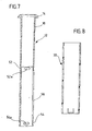
- einen axialen Schnitt durch dieses Führungsrohr;
- Fig. 8
- einen axialen Schnitt durch ein Verstärkungs- und Schutzrohr, welches auf das Führungsrohr aufschiebbar und im unteren Bereich der Fig. 1 bzw. der Fig. 2 in einer Seitenansicht dargestellt ist;
- Fig. 9A
- eine Draufsicht auf ein zwischen Führungsrohr und Schutzrohr anzubringendes, Sprengring-artiges Ringelement;
- Fig. 9B
- einen Schnitt nach der Linie 9B-9B in Fig. 9A;
- Fig. 10A
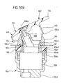
- einen axialen Schnitt durch die separate Ventileinheit der Wasserauslaufeinrichtung, und zwar nach Montage der Ventileinheit in einer Öffnung einer im Schnitt dargestellten Trägerplatte, wobei die Mischventilkartusche der Ventileinheit nur schematisch und in der Seitenansicht dargestellt wurde und das Bedienungselement der Ventileinheit sich in derjenigen Position befindet, in der die Mischventilkartusche geschlossen ist, und
- Fig. 10B
- eine der Fig. 10A entsprechende Schnittdarstellung, wobei jedoch das Bedienungselement eine Stellung einnimmt, in der die Mischventilkartusche voll geöffnet ist.
- Fig. 1
- a side view of the actual water outlet device mounted in a carrier plate shown in section without a valve unit, the water outlet device assuming its upper position of use;
- Fig. 2
- the parts shown in Figure 1 again in a side view, but after lowering the actual water outlet device in its lower position.
- Fig. 3
- an axial section through an assembly of the water outlet device, which comprises an upper and a lower pipe firmly connected to this, which together form the slidably guided straight pipe section, and the guide for this pipe section, the latter assuming its upper position of use;
- Fig. 4
- an axial section corresponding to Figure 3, but with the straight tube area in its lower position;
- Fig. 5
- an axial section through a plug-in into the upper end of the upper tube, which is to be part of a hose shower;
- Fig. 6
- a side view of the guide tube shown in Figures 3 and 4 in section and forming the guide;
- Fig. 7
- an axial section through this guide tube;
- Fig. 8
- an axial section through a reinforcing and protective tube which can be pushed onto the guide tube and is shown in a side view in the lower region of FIG. 1 and FIG. 2;
- Figure 9A
- a plan view of a snap ring-like ring element to be attached between the guide tube and the protective tube;
- Figure 9B
- a section along the line 9B-9B in Fig. 9A;
- Figure 10A
- an axial section through the separate valve unit of the water outlet device, namely after mounting the valve unit in an opening of a carrier plate shown in section, the mixing valve cartridge of the valve unit was only shown schematically and in side view and the control element of the valve unit is in that position in that the mixing valve cartridge is closed, and
- Figure 10B
- 10A is a sectional view corresponding to FIG. 10A, but the control element assumes a position in which the mixing valve cartridge is fully open.
Die Fig. 1 zeigt eine Trägerplatte 10, und zwar.in einem
Schnitt längs einer vertikalen Ebene, welche vor der erfindungsgemäßen
Wasserauslaufeinrichtung liegt, so daß eine von
letzterer durchgriffene Öffnung in Form eines kreisrunden
Loches in der Trägerplatte nicht erkennbar ist. In diese
Öffnung ist von oben ein Führungsrohr 12 eingesetzt, welches
an seinem oberen Ende einen Ringbund 14 besitzt, dessen
Außendurchmesser größer ist als die Öffnung in der Trägerplatte
10 und der auf letzterer aufliegt. Unterhalb des
Ringbundes 14 hat das Führungsrohr 12 ein Außengewinde 16,
auf das eine Befestigungsmutter 18 aufgeschraubt ist, mit
deren Hilfe die Trägerplatte 10 zwischen dem Ringbund 14 und
der Befestigungsmutter 18 eingespannt werden kann. Auf das
Führungsrohr 12 ist von unten ein Schutzrohr 20 aufgeschoben
und in später noch zu erläuternder Weise gehalten.1 shows a
Ein entlang einer vertikalen, d. h. senkrecht zur Trägerplatte
10 verlaufenden Rohrachse 22 im Führungsrohr 12 verschiebbar
und um diese Achse verschwenkbar gehaltener Wasserauslaufkran
24 besitzt, soweit dies die Fig. 1 erkennen läßt,
ein ungefähr umgekehrt L-förmig gestaltetes oberes Rohr 26
mit einem vertikalen Rohrabschnitt 28, einem Rohrbogen 30 und
einem horizontalen Rohrabschnitt 32, in dessen gemäß Fig. 1
rechtes Ende ein mit einer nach unten gerichteten Wasserauslauföffnung
34 versehenes Mundstück 36 eingesteckt ist, so
daß es aus dem Rohrabschnitt 32 gemäß Fig. 1 nach rechts
herausgezogen werden kann. Dieses Mündungsstück 36 bildet
eine Schlauchbrause, und der vom auslaufenden Wasser gebildete
Brausestrahl wurde mit 40 bezeichnet.One along a vertical, i.e. H. perpendicular to the
Während die Fig. 1 den Wasserauslaufkran 24 in seiner oberen
Gebrauchsstellung zeigt, nimmt er in Fig. 2 seine untere
Stellung ein, in der der vertikale Rohrabschnitt 28 vollständig
in das Führungsrohr 12 eingeschoben ist, jedoch ein
später noch näher zu beschreibendes unteres Rohr 44, das am
unteren Ende des vertikalen Rohrabschnitts 28 befestigt ist,
nach unten aus dem Schutzrohr 20 herausragt.1 the
Die Figuren 3 und 4 lassen erkennen, daß der vertikale Rohrabschnitt
28 des oberen Rohres 26 mit dem unteren Rohr 44
mittels einer Verschraubung 46 verbunden ist und wie ein
gerader Rohrbereich 48, welcher vom unteren Rohr 44 zusammen
mit dem vertikalen Rohrabschnitt 28 gebildet wird, im Führungsrohr
12 geführt und gehalten ist, nämlich so, daß die
von den beiden Rohren 26 und 44 gebildete Einheit in Richtung
der Rohrachse 22 verschiebbar und um diese Achse drehbar ist
- im Querschnitt ist sowohl die Innenkontur des Führungsrohrs
12 als auch die Außenkontur des geraden Rohrbereichs 48
kreisförmig. In einer inneren Ringnut des Ringbundes 14 ist
ein elastischer Dichtring 50 angeordnet, welcher unter leichter
Vorspannung gegen den Außenumfang des geraden Rohrbereichs
48 anliegt und nicht nur den Ringspalt zwischen Führungsrohr
12 und geradem Rohrbereich 48 abdichtet, sondern
auch dazu führt, daß die von den beiden Rohren 26 und 44
gebildete Einheit aus ihrer oberen, in den Figuren 1 und 3
gezeigten Gebrauchsstellung nicht frei in ihre in den Figuren
2 und 4 dargestellte untere Stellung herabfallen kann, sondern
langsam nach unten gleitet, wenn diese sich in ihrer
oberen Gebrauchsstellung befindliche Einheit losgelassen wird
und eine später noch zu beschreibende Arretiervorrichtung
unwirksam ist.Figures 3 and 4 show that the
Am Außenumfang des Führungsrohrs 12 sind in axialem Abstand
voneinander eine obere Ringnut 52 und eine untere Ringnut 54
vorgesehen, zwischen denen sich eine Kulisse 56 befindet, die
Bestandteil der erwähnten Arretiervorrichtung ist und die Gestalt
eines in das Führungsrohr 12 eingearbeiteten Schlitzes
hat, dessen Verlauf später noch erläutert werden wird. Mit
dieser Kulisse wirkt ein am unteren Rohr 44 vorgesehener Vorsprung
zusammen, bei dem es sich um eine in diesen Schlitz
eingreifende Madenschraube 58 handelt, welche in eine Gewindebohrung
60 des unteren Rohres 44 eingeschraubt ist und mit
dem Außenumfang des Führungsrohrs 12 bündig abschließt.On the outer circumference of the
Das in Fig. 5 näher dargestellte Mundstück 36 hat einen an
seinem Außenumfang abgestuften, gemäß Fig. 5 linken Endbereich
62 mit einer kreiszylindrischen Ringfläche 64 und einem
Außengewinde 66; wie die Fig. 5 zeigt, ist der Durchmesser
der Ringfläche 64 kleiner als der Außendurchmesser des Mundstücks
36 rechts vom Endbereich 62, und das Außengewinde 66
hat einen Außendurchmesser, welcher seinerseits kleiner ist
als der Durchmesser der Ringfläche 64. Der Endbereich 62 ist
in das gemäß den Figuren 1 bis 4 rechte Ende des horizontalen
Rohrabschnitts 32 einsteckbar; zu diesem Zweck besitzt der
letztere einen kreiszylindrischen Paßsitz 68, dessen Innendurchmesser
dem Außendurchmesser der Ringfläche 64 entspricht.
Auf das Außengewinde 66 ist ein nicht dargestellter
flexibler Schlauch aufgeschraubt, welcher durch das obere
Rohr 26 und das untere Rohr 44 verläuft und über den dem
Mundstück 36 Leitungswasser zugeführt werden kann, sei es
Kaltwasser oder Warmwasser oder Mischwasser mit der gewünschten
Temperatur. Dieses fließt dann in einen Innenkanal 70 des
Mundstücks 36, in dessen Wasserauslaßöffnung 34 z. B. ein
üblicher Siebeinsatz eingeschraubt werden kann.The
Wie die Fig. 6 erkennen läßt, besteht der die Kulisse 56 bildende
Schlitz im Führungsrohr 12 aus einem oberen, horizontal
verlaufenden ersten Schlitzbereich 56a, einem vertikal verlaufen
zweiten Schlitzbereich 56b und einem unteren, gleichfalls
horizontal verlaufenden dritten Schlitzbereich 56c,
welche zusammen eine Kulisse mit der Gestalt eines liegenden
U bilden. Am Übergang des oberen horizontalen Schlitzbereichs
56a in den vertikal verlaufenden zweiten Schlitzbereich 56b
bildet der horizontale obere Schlitzbereich 56a einen Höcker
56d, wobei der die Kulisse 56 bildende Schlitz jedoch überall
eine Schlitzbreite aufweist, die gleich oder ganz geringfügig
größer ist als der Außendurchmesser der Madenschraube 58. Der
obere horizontale Schlitzbereich 56a (inklusive Höcker 56d)
und der untere horizontale Schlitzbereich 56c erstrecken sich
jeweils über einen Umfangswinkel des Führungsrohrs 12, welcher
frei wählbar ist und beispielsweise etwas mehr als 90°
oder etwas mehr als 180° betragen kann, um den Wasserauslaufkran
24 (unter Berücksichtigung des Durchmessers der Madenschraube
58) um die Rohrachse 22 um 90° bzw. 180° verschwenken
zu können (die gemäß Fig. 6 linken Enden der beiden
Schlitzbereiche 56a und 56c sind in der Zeichnung nicht erkennbar).As can be seen in FIG. 6, the
Die Fig. 7 mit einem Längsschnitt durch das Führungsrohr 12
dient nur dem Zweck darzustellen, daß in der Wand des Führungsrohrs
im Bereich der Ringnuten 52 und 54 mehrere Langlöcher
52a bzw. 54a vorgesehen sind, welche über den Umfang
des Führungsrohrs 12 in Abständen voneinander verteilt angeordnet
sind und deren Zweck nachfolgend noch erläutert werden
wird.7 with a longitudinal section through the
Die Fig. 8 zeigt das in den Figuren 1 und 2 dargestellte
Schutzrohr 20 in einem Längsschnitt.8 shows that shown in FIGS. 1 and 2
In jede der beiden Ringnuten 52 und 54 läßt sich ein in den
Figuren 9A und 9B dargestelltes Sprengring-artiges Ringelement
74 aus einem elastischen Werkstoff einsetzen; dieses
besitzt an seinem Innenumfang drei Vorsprünge 74a, welche
dann in die Langlöcher 52a bzw. 54a eingreifen und ein Verdrehen
der Ringelemente 74 gegenüber dem Führungsrohr 12 verhindern.
Der Durchmesser des Grunds der Ringnut 52 bzw. 54,
der Innendurchmesser des Schutzrohrs 20, der Außendurchmesser
der Ringelemente 74 und deren Innendurchmesser zwischen den
Vorsprüngen 74a sind nun so aufeinander abgestimmt, daß,
nachdem das Schutzrohr 20 über das Führungsrohr 12 und die
beiden Ringelemente 74 geschoben worden ist, das Schutzrohr
20 über die Ringelemente 74 das Führungsrohr 12 in radialer
Richtung zusammenpreßt; außerdem verhindert das untere Ringelement
74, daß Schmutz von unten in den Ringspalt zwischen
dem Schutzrohr 20 und dem Führungsrohr 12 und damit in den
Bereich der Kulisse 56 eindringen kann. Zu diesem Zweck werden
die Ringelemente 74 so am Führungsrohr 12 befestigt, daß
ihre Lücken 74b - in Richtung der Rohrachse 22 gesehen -
nicht im Bereich der Kulisse 56 liegen. Die Länge des Schutzrohres
20 muß also mindestens dem axialen Abstand der beiden
Ringnuten 52 und 54 voneinander entsprechen und ist vorzugsweise
etwas größer als dieser Abstand.In each of the two
Wie sich aus den Figuren 3 und 4 in Verbindung mit Fig. 6
ergibt, ist der Wasserauslaufkran 24 in seiner oberen Gebrauchsstellung
bzw. in seiner unteren Stellung immer dann
verriegelt, wenn sich die Madenschraube 58 im oberen Schlitzbereich
56a links (gemäß Fig. 6) vom Höcker 56d bzw. im unteren
Schlitzbereich 56c links vom vertikalen Schlitzbereich
56b befindet. Ist der Wasserauslaufkran 24 in seiner oberen
Gebrauchsstellung, so kann die Madenschraube 58 entweder
durch leichtes Anheben und geringfügiges Verschwenken des
Wasserauslaufkrans 24 über den Höcker 56d hinweggehoben und
über den vertikalen Schlitzbereich 56b gebracht werden, dank
der abgerundeten, gemäß Fig. 6 linken Flanke des Höckers 56d
läßt sich letzterer aber auch allein durch Verschwenken des
Wasserauslaufkrans 24 überwinden, weil dabei die linke Flanke
des Höckers 56d automatisch dazu führt, daß der Wasserauslaufkran
geringfügig angehoben wird.As can be seen from FIGS. 3 and 4 in connection with FIG. 6
results, the
Die Figuren 10A und 10B zeigen eine Trägerplatte 10', bei der
es sich um die in den Figuren 1 und 2 gezeigte Trägerplatte
10, aber auch um eine andere Trägerplatte handeln kann. Auch
die Trägerplatte 10' hat eine insbesondere kreisförmige Öffnung
100, in der eine als Ganzes mit 102 bezeichnete Ventileinheit
befestigt ist. Diese umfaßt ein topfförmiges Gehäuse
104, eine von letzterem aufgenommene handelsübliche Mischventilkartusche
106 mit einem Steuerzapfen 108 zur Betätigung
der Mischventilkartusche, eine Mutter 110 und ein Bedienungselement
112 mit einem Griff 114 zur Betätigung der Ventileinheit
102. Das Gehäuse 104 hat ein Gehäuseunterteil 104a und
ein Gehäuseoberteil 104b, welche nach dem Einsetzen der
Mischventilkartusche 106 in das Gehäuseunterteil über eine
Verschraubung 104c miteinander verbunden werden. Das Gehäuseoberteil
104b hat einen Kragen 104d, welcher die Öffnung 104
durchgreift und an dem mittels einer Verschraubung 104e die
Mutter 110 befestigt werden kann. Unterhalb der Verschraubung
104e hat der Kragen 104d einen Außendurchmesser, welcher dem
Durchmesser der Öffnung 100 entspricht, so daß sich die Ventileinheit
102 in der Trägerplatte 10' keinesfalls verschieben
kann, und damit das Gehäuseoberteil 104b von unten in die
Öffnung 100 eingesetzt werden kann, darf der Außendurchmesser
des Kragens 104d im Bereich der Verschraubung 104e keinesfalls
größer sein als der Durchmesser dieser Öffnung. Damit
die über die Oberseite der Trägerplatte 10' nach oben hinausragenden
Teile der Ventileinheit 102 unabhängig von der Dicke
der Trägerplatte 10' stets gleich weit über diese nach oben
überstehen, sitzt auf einer vom Gehäuseoberteil 104b gebildeten
Abstützschulter 104f ein austauschbarer Distanzring 116,
zwischen dem und der Mutter 110 die Trägerplatte 10' eingespannt
ist, nachdem die Mutter angezogen wurde. Durch verwendung
eines Distanzrings 116 entsprechender Dicke - gemessen
in Richtung senkrecht zu der von der Trägerplatte 10' definierten
Ebene - läßt sich also die Dicke der Trägerplatte 10'
berücksichtigen (bei einer dickeren Trägerplatte wird ein
weniger dicker Distanzring 120 verwendet und umgekehrt), so
daß durch Wahl eines entsprechenden Distanzrings gewährleistet
werden kann, daß die Ventileinheit 102 stets gleich weit
nach oben über die Oberseite der Trägerplatte 10' hinausragt.FIGS. 10A and 10B show a carrier plate 10 'in which
it is the carrier plate shown in Figures 1 and 2
10, but can also be a different carrier plate. Also
the carrier plate 10 'has a particularly
Mischventilkartuschen der in Rede stehenden Art lassen sich
in folgender Weise betätigen: Durch Kippen des Steuerzapfens
108 aus seiner in Fig. 10A dargestellten vertikalen Position
in die in Fig. 10B gezeichnete schräge Position läßt sich die
Mischventilkartusche im Laufe der Kippbewegung vollständig
öffnen - in der vertikalen Position des Steuerzapfens ist sie
ganz geschlossen -, und durch Drehen des Steuerzapfens 108 um
seine Zapfenachse 108a läßt sich jedes beliebige Mischverhältnis
zwischen Kaltwasser und Warmwasser einstellen. Um
diese Bewegungen des Steuerzapfens 108 bewirken zu können,
andererseits aber zu verhindern, daß Flüssigkeiten und
Schmutz von oben in die von der Ringmutter 110 und dem Kragen
104d gebildete Öffnung eindringen können, bildet das mittels
geeigneter Schraubmittel am Steuerzapfen 108 befestigte Bedienungselement
112 eine Kappe 120, deren Umfangsbereich
einen Kappenmantel 122 mit einer abgeschrägten Unterkante 124
bildet. Durch die Abschrägung dieser Unterkante wird erreicht,
daß sich das Bedienungselement 112 in die in Fig. 10B
dargestellte gekippte Position bringen läßt, weil der auf der
der Schrägstellung zugeordneten Seite befindliche Unterkantenbereich
124a in der in Fig. 10A gezeigten Schließstellung
der Mischventilkartusche 106 einen größeren Abstand von
der Trägerplatte 10' hat als der gegenüberliegende Unterkantenbereich
124b. Gleichzeitig überfängt die Kappe 120 die
Mutter 110 jedoch in allen Stellungen des Bedienungselements
112 so weit, daß in der Praxis Flüssigkeiten, Schmutz und
dergleichen nicht in die von der Mutter 110 und dem Kragen
104d gebildete Öffnung der Ventileinheit 102 gelangen können.Mixing valve cartridges of the type in question can be
Operate in the following way: By tilting the
Nachdem die beigefügte Zeichnung im Zusammenhang mit der vorstehenden Beschreibung des zeichnerisch dargestellten Ausführungsbeispiels letzteres in allen Einzelheiten verständlich macht, werden die im folgenden beschriebenen alternativen Ausführungsformen der erfindungsgemäßen Einrichtung vom Fachmann auch ohne deren zeichnerische Darstellung ohne weiteres verstanden werden.After the attached drawing in connection with the Above description of the illustrated Embodiment of the latter understandable in all details makes, are described below alternative embodiments of the device according to the invention by the specialist even without their graphic representation can be easily understood.
Bei der zeichnerisch dargestellten Ausführungsform hat
die Kulisse 56 eine ungefähr C-förmige Gestalt; damit ein
und dieselbe Wasserauslaufeinrichtung z.B. mit Einbauspülen
kombiniert werden kann, von denen die einen ein
Spülbecken rechts der Montagestelle für die Wasserauslaufeinrichtung
und die anderen links dieser Stelle haben,
sollte der dem geraden Rohrbereich 48 entsprechende Rohrbereich
einer modifizierten Ausführungsform nicht nur um
ungefähr 90°, sondern um ungefähr 180° schwenkbar sein,
wobei es vorteilhaft wäre, wenn dieser Rohrbereich in
beiden Schwenkendstellungen abgesenkt werden könnte. Dies
läßt sich in einfacher Weise dadurch erreichen, daß die
Kulisse - natürlich in abgewickelter Form - ungefähr die
Gestalt eines Rechtecks hat. Has in the illustrated embodiment
the
Bei der dargestellten Ausführungsform ist die Kulisse in
der äußeren Führung 12 vorgesehen, das mit der Kulisse
zusammenwirkende Arretierglied 58 an dem verschwenkbaren
und höhenverstellbaren geraden Rohrbereich 48. Bei einer
Modifikation der erfindungsgemäßen Einrichtung ist hingegen
die Kulisse in den Außenumfang des geraden Rohrbereichs
eingearbeitet und das Arretierglied an der Führung angebracht.In the illustrated embodiment, the backdrop is in
the
Bei einer weiteren Variante treten an die Stelle der Kulisse zwei in vertikalem Abstand voneinander angeordnete Ringnuten und an die Stelle des starren Arretiergliedes ein in radialer Richtung gefedertes Rastelement mit abgerundetem Kopfende zum Einfallen in die obere bzw. untere Ringnut. Bevorzugt werden solche Ausführungsformen dieser Variante, welche drei solcher gefederter Rastelemente besitzen, die in gleichen Winkelabständen voneinander verteilt sind, um so eine Zentrierwirkung herbeizuführen. Diese beiden vorstehend beschriebenen Modifikationen bringen den Vorteil mit sich, daß die Wasserauslaßöffnung über volle 360° geschwenkt werden kann.In another variant, the Backdrop two vertically spaced Ring grooves and in place of the rigid locking member a locking element sprung in the radial direction with rounded head end for falling into the upper or lower ring groove. Such embodiments are preferred this variant, which three such spring-loaded locking elements possess that at equal angular distances from each other are distributed so as to bring about a centering effect. These two modifications described above bring the advantage that the water outlet opening can be swiveled through a full 360 °.
Claims (26)
- Mixing tap with a water outlet device for assembly on a plate-like carrier (10; 10'), comprising a water outlet pipe leading to a water outlet opening (34), a straight pipe section (48) mountable in an opening of the carrier with a pipe axis (22) extending approximately vertically in relation to the upper side of the carrier and adjoined at the top by an end pipe section (32) extending approximately vertically in relation to the pipe axis (22), and at least one operating element (112) for a water outlet valve and water mixing device (102), the straight pipe section (48) being mountable in the carrier opening in a guide (12) fixedly attachable with respect to the carrier (10; 10') for displacement in the direction of the pipe axis (22) and thus being displaceable from an upper operating position into a lower position in which the water outlet opening (34) is located immediately adjacent to the level of the upper side of the carrier, characterized in that(a) a mouthpiece (36) provided with the water outlet opening (34) and connected to a flexible water hose arranged in the straight pipe section (48) and in the end pipe section (32) is inserted into the free end of the end pipe section (32),
and in that(b) the operating element (112) is part of a valve unit (102) mountable separately from the displaceable parts (36, 26, 44) in a plate-like carrier (10'). - Device in accordance with Claim 1, characterized in that the straight pipe section (48) is held in the guide (12) for rotation about its pipe axis (22).
- Device in accordance with Claim 1 or 2, characterized in that the guide (12) surrounds the straight pipe section (48) all the way round.
- Device in accordance with Claim 3, characterized in that the guide (12) is provided with an elastic seal (50) which rests all the way round against the outer circumference of the straight pipe section (48).
- Device in accordance with any one or several of the preceding claims, characterized in that a locking device (56, 58) is provided for holding the straight pipe section (48) in its upper operating position and is designed in such a way that the straight pipe section (48) is manually lowerable into its lower position.
- Device in accordance with Claim 5, characterized in that the locking device (56, 58) comprises a coulisse element (56) and a locking element (58) co-operating with the coulisse element (56), one of said elements (56) being fixedly mountable with respect to the carrier (10) and the other element (58) with respect to the straight pipe section (48).
- Device in accordance with Claim 6, characterized in that the coulisse element (56) is provided on the guide (12) and the locking element (58) is fixedly connected to the straight pipe section (48).
- Device in accordance with any one or several of the preceding claims, characterized in that the guide comprises a guide pipe (12) attachable to the carrier (10).
- Device in accordance with Claim 8, characterized in that the guide pipe (12) is provided at its upper end with a ring collar (14) which can be placed from above against the carrier (10).
- Device in accordance with Claim 9, characterized in that the guide pipe (12) is provided below the ring collar (14) with an external thread (16) for a nut (18) which is tightenable from below against the carrier (10).
- Device in accordance with Claim 4 and any one or several of Claims 8 to 10, characterized in that the seal (50) is arranged in the ring collar (14).
- Device in accordance with Claim 7 and any one or several of Claims 8 to 11, characterized in that the coulisse element (56) is configured as a groove or a slot with an upper, approximately horizontally extending, first coulisse element section (56a), an approximately vertically extending, second coulisse element section (56b), and a lower, approximately horizontally extending, third coulisse element section (56c), and in that the locking element is designed as a projection (58) for engagement in the coulisse element (56).
- Device in accordance with Claim 12, characterized in that the upper, first coulisse element section (56a) forms a hump (56d), over which the projection (58) has to be moved by raising the straight pipe section (48) before the projection can be brought into the vertically extending, second coulisse element section (56b).
- Device in accordance with Claim 13, characterized in that the hump (56d) is located at the transition from the first coulisse element section (56a) to the second coulisse element section (56b).
- Device in accordance with any one or several of Claims 12 to 14 and any one or several of Claims 8 to 11, characterized in that the coulisse element (56) is configured as a slot formed in the guide pipe (12).
- Device in accordance with Claim 15 and any one or several of Claims 12 to 14, characterized in that the projection is in the form of a screw (58) screwable from outside into the straight pipe section (48).
- Device in accordance with any one or several of the preceding claims, characterized in that the straight pipe section (48) is formed by a straight lower pipe (44) and an upper pipe (26) releasably connected thereto.
- Device in accordance with Claim 17, characterized in that the lower pipe (44) and the upper pipe (26) are screwed to one another.
- Device in accordance with any one or several of the preceding claims, characterized in that a pipe bend (30) is located between the straight pipe section (48) and the end pipe section (32).
- Device in accordance with any one or several of the preceding claims, characterized in that the end pipe section (32) is located immediately above the level of the upper side of the carrier when the straight pipe section (48) is in its lower position.
- Device in accordance with any one or several of Claims 8 to 20, characterized by a reinforcing protective pipe (20) slipped onto the guide pipe (12).
- Device in accordance with Claim 21, characterized in that at least two elastic snap-ring-like ring elements (74) are arranged in axially spaced relation to one another between the guide pipe (12) and the protective pipe (20), each of these elements being pressed in radial direction by the protective pipe (20) against the guide pipe (12).
- Device in accordance with any one or several of the preceding claims, characterized in that the valve unit (102) comprises an approximately pot-shaped housing (104) having a collar (104d) for engaging through an opening (100) in the said carrier (10'), and in that a nut (110) screwable onto an external thread (104e) of the collar and positionable against the upper side of the said carrier (10') is provided.
- Device in accordance with Claim 23, characterized in that the housing (104) has a supportive shoulder (104f) pointing upwards and surrounding the foot of the collar (104d), in that a mixing valve cartridge (106) with a tiltable and rotatable control pin (108) projecting upwards and extending into the collar (104d) is arranged in the housing (104), and in that an exchangeable spacer ring (116) enclosing the collar (104d) and resting on the supportive shoulder (104f) is provided for clamping the said carrier (10') between the nut (110) and the spacer ring (116).
- Device in accordance with Claim 24, characterized in that the operating element (112) has a cap (120) which is releasably attached to the control pin (108) and engages over the nut (110) and/or the collar (104d), and a handle (114) on the cap (120) for actuating the control pin (108).
- Device in accordance with Claim 25, characterized in that the control pin (108) is tiltable from a position of rest in which the mixing valve cartridge (106) is closed and the control pin extends approximately vertically to the upper side of the said carrier (10') into an inclined position in which the mixing valve cartridge is completely open, and in that a peripheral area (122) of the cap (120) engaging over the nut (110) and/or the collar (104d) is shorter on the side associated with the inclined position than on the opposite side.
Applications Claiming Priority (2)
| Application Number | Priority Date | Filing Date | Title |
|---|---|---|---|
| DE4440904 | 1994-11-17 | ||
| DE4440904A DE4440904A1 (en) | 1994-11-17 | 1994-11-17 | Mixer tap water outlet device |
Publications (3)
| Publication Number | Publication Date |
|---|---|
| EP0712964A1 EP0712964A1 (en) | 1996-05-22 |
| EP0712964B1 true EP0712964B1 (en) | 2003-03-12 |
| EP0712964B2 EP0712964B2 (en) | 2006-11-29 |
Family
ID=6533453
Family Applications (1)
| Application Number | Title | Priority Date | Filing Date |
|---|---|---|---|
| EP95117456A Expired - Lifetime EP0712964B2 (en) | 1994-11-17 | 1995-11-06 | Mixing valve water outlet |
Country Status (3)
| Country | Link |
|---|---|
| EP (1) | EP0712964B2 (en) |
| AT (1) | ATE234395T1 (en) |
| DE (2) | DE4440904A1 (en) |
Families Citing this family (6)
| Publication number | Priority date | Publication date | Assignee | Title |
|---|---|---|---|---|
| FR2847601B1 (en) * | 2002-11-22 | 2006-06-23 | Dominique Vaillaut | MIXER TAP WITH SEPARATE MIXTURE MECHANISM |
| US8230882B2 (en) * | 2007-02-21 | 2012-07-31 | Neoperl Gmbh | Telescoping water outlet |
| DE202009004785U1 (en) * | 2009-05-06 | 2010-09-23 | Hettich Holding Gmbh & Co. Ohg | Device for dispensing water |
| ITPN20110035A1 (en) * | 2011-05-18 | 2012-11-19 | Geda S R L | SINGLE-LEVER BLEND MIXER TAP |
| DE102013003827A1 (en) * | 2013-03-07 | 2014-09-11 | Grohe Ag | plumbing fixture |
| DE202017105096U1 (en) * | 2017-08-24 | 2018-08-30 | Reich Gmbh Regel- Und Sicherheitstechnik | Water fitting, in particular for a caravan, caravan, Motorcaravan or a boat, arrangement of such a water fitting to a piece of furniture, and trailer and vehicle |
Citations (2)
| Publication number | Priority date | Publication date | Assignee | Title |
|---|---|---|---|---|
| DE3135840C1 (en) * | 1981-09-10 | 1983-06-09 | Degussa Ag, 6000 Frankfurt | 2-Azido-3-benzyloxy-propionic acid benzyl ester and process for its preparation |
| EP0095523B1 (en) * | 1982-06-01 | 1986-11-26 | Stanadyne Inc. | High rise kitchen spout |
Family Cites Families (11)
| Publication number | Priority date | Publication date | Assignee | Title |
|---|---|---|---|---|
| FR990965A (en) * | 1949-07-19 | 1951-09-28 | Improvements to taps for washbasins | |
| FR1259021A (en) * | 1960-03-11 | 1961-04-21 | A E R Ets | Mixer with swivel spout, especially for sink |
| DE1956579A1 (en) * | 1969-11-11 | 1971-05-19 | Hansa Metallwerke Ag | Water inlet for seat washbasins or other sanitary basins |
| US3680780A (en) * | 1971-02-23 | 1972-08-01 | Crosweller & Co Ltd W | Ablutionary appliances |
| DE3231214A1 (en) * | 1982-08-21 | 1984-02-23 | Friedrich Grohe Armaturenfabrik Gmbh & Co, 5870 Hemer | Sanitary fitting |
| DE3508893C2 (en) * | 1985-03-13 | 1994-08-04 | Ideal Standard | Fixing arrangement of a sanitary battery |
| DK167450B1 (en) * | 1986-05-14 | 1993-11-01 | Gevipi Ag | WATER TAPS WITH EXPOSURE SUPPLIES THAT CAN BE ADJUSTED IN MANY WAYS |
| DE4029792A1 (en) * | 1990-09-20 | 1992-03-26 | Grohe Kg Hans | Hand shower fastener with hose holder - has through hole in holder, with topend supporting shower head |
| FR2672369B1 (en) * | 1991-01-16 | 1995-01-27 | Masco Corp | REMOVABLE SANITARY SHOWER AND ASSEMBLY METHOD. |
| CH686791A5 (en) * | 1991-11-28 | 1996-06-28 | Kugler Fonderie Robinetterie | fixture. |
| DE9302384U1 (en) * | 1993-02-18 | 1993-04-08 | Reich GmbH Regel- und Sicherheitstechnik, 6345 Eschenburg | Water outlet on water fitting suitable for use in camping areas |
-
1994
- 1994-11-17 DE DE4440904A patent/DE4440904A1/en not_active Withdrawn
-
1995
- 1995-11-06 AT AT95117456T patent/ATE234395T1/en active
- 1995-11-06 EP EP95117456A patent/EP0712964B2/en not_active Expired - Lifetime
- 1995-11-06 DE DE59510580T patent/DE59510580D1/en not_active Expired - Lifetime
Patent Citations (2)
| Publication number | Priority date | Publication date | Assignee | Title |
|---|---|---|---|---|
| DE3135840C1 (en) * | 1981-09-10 | 1983-06-09 | Degussa Ag, 6000 Frankfurt | 2-Azido-3-benzyloxy-propionic acid benzyl ester and process for its preparation |
| EP0095523B1 (en) * | 1982-06-01 | 1986-11-26 | Stanadyne Inc. | High rise kitchen spout |
Also Published As
| Publication number | Publication date |
|---|---|
| EP0712964B2 (en) | 2006-11-29 |
| ATE234395T1 (en) | 2003-03-15 |
| DE4440904A1 (en) | 1996-05-23 |
| EP0712964A1 (en) | 1996-05-22 |
| DE59510580D1 (en) | 2003-04-17 |
Similar Documents
| Publication | Publication Date | Title |
|---|---|---|
| DE2734131C2 (en) | Pouring tap | |
| DE2528717A1 (en) | HANDLE TAP | |
| DE3403562A1 (en) | SHUT-OFF VALVE | |
| DE7710413U1 (en) | DEVICE FOR INDICATING THE POSITION OF AN ACTUATOR | |
| EP3021023B1 (en) | Sanitary fitting with offset operating element tilt axis | |
| EP0712964B2 (en) | Mixing valve water outlet | |
| DE2523342C3 (en) | Single-point mixer tap | |
| EP1946686B1 (en) | Partition wall, in particular shower partition wall | |
| EP0501191A1 (en) | Shower partition | |
| DE4229949A1 (en) | Support foot for vehicle roof rack - has tensioner which presses foot against vehicle roof in locking position | |
| EP2226540B1 (en) | Sanitary built-in fitting | |
| DE3205205C2 (en) | Faucet outlet | |
| EP0982441B1 (en) | Sanitary single-handle faucet | |
| DE2907565C2 (en) | Combined self-closing and mixing valve | |
| EP1983116A1 (en) | Device for actuating the organ of a bathroom article and method for mounting the key of the device for operating the organ of a bathroom article | |
| EP0662559B1 (en) | Doorhinge | |
| DE8807606U1 (en) | Sanitary regulating and shut-off device | |
| EP2317193A1 (en) | Sanitary fitting with sliding mounted actuation lever | |
| EP1255005B1 (en) | Bolt fitting | |
| EP2365165A2 (en) | Fitting and shower partition | |
| DE3823867A1 (en) | LOCK, IN PARTICULAR POCKET LOCK, WITH LOCK NUT AND CONNECTED NUT ARM | |
| EP3171043B1 (en) | Kitchen fitting | |
| DE102007057611B4 (en) | Turning handle for actuating a valve spindle of a sanitary fitting | |
| DE10243304A1 (en) | Pivoting outlet for sanitary fittings comprises an insert rotationally fixed on a base or an outlet spout and cooperating with the other element to limit the pivoting movement | |
| EP1508662A1 (en) | Door hinge |
Legal Events
| Date | Code | Title | Description |
|---|---|---|---|
| PUAI | Public reference made under article 153(3) epc to a published international application that has entered the european phase |
Free format text: ORIGINAL CODE: 0009012 |
|
| AK | Designated contracting states |
Kind code of ref document: A1 Designated state(s): AT BE DE FR GB IT NL |
|
| RAP1 | Party data changed (applicant data changed or rights of an application transferred) |
Owner name: M & Z S.P.A. Owner name: BLANCO GMBH & CO. KG |
|
| 17P | Request for examination filed |
Effective date: 19961030 |
|
| 17Q | First examination report despatched |
Effective date: 20010402 |
|
| GRAH | Despatch of communication of intention to grant a patent |
Free format text: ORIGINAL CODE: EPIDOS IGRA |
|
| GRAH | Despatch of communication of intention to grant a patent |
Free format text: ORIGINAL CODE: EPIDOS IGRA |
|
| RAP1 | Party data changed (applicant data changed or rights of an application transferred) |
Owner name: M & Z S.P.A. Owner name: BLANCO GMBH + CO KG |
|
| GRAA | (expected) grant |
Free format text: ORIGINAL CODE: 0009210 |
|
| AK | Designated contracting states |
Designated state(s): AT BE DE FR GB IT NL |
|
| PG25 | Lapsed in a contracting state [announced via postgrant information from national office to epo] |
Ref country code: NL Free format text: LAPSE BECAUSE OF FAILURE TO SUBMIT A TRANSLATION OF THE DESCRIPTION OR TO PAY THE FEE WITHIN THE PRESCRIBED TIME-LIMIT Effective date: 20030312 Ref country code: GB Free format text: LAPSE BECAUSE OF FAILURE TO SUBMIT A TRANSLATION OF THE DESCRIPTION OR TO PAY THE FEE WITHIN THE PRESCRIBED TIME-LIMIT Effective date: 20030312 |
|
| REG | Reference to a national code |
Ref country code: GB Ref legal event code: FG4D Free format text: NOT ENGLISH |
|
| REF | Corresponds to: |
Ref document number: 59510580 Country of ref document: DE Date of ref document: 20030417 Kind code of ref document: P |
|
| NLV1 | Nl: lapsed or annulled due to failure to fulfill the requirements of art. 29p and 29m of the patents act | ||
| GBV | Gb: ep patent (uk) treated as always having been void in accordance with gb section 77(7)/1977 [no translation filed] |
Effective date: 20030312 |
|
| PG25 | Lapsed in a contracting state [announced via postgrant information from national office to epo] |
Ref country code: BE Free format text: LAPSE BECAUSE OF NON-PAYMENT OF DUE FEES Effective date: 20031130 |
|
| ET | Fr: translation filed | ||
| PLBI | Opposition filed |
Free format text: ORIGINAL CODE: 0009260 |
|
| PLAX | Notice of opposition and request to file observation + time limit sent |
Free format text: ORIGINAL CODE: EPIDOSNOBS2 |
|
| 26 | Opposition filed |
Opponent name: GROHE WATER TECHNOLOGY AG & CO. KG Effective date: 20031204 |
|
| PLAX | Notice of opposition and request to file observation + time limit sent |
Free format text: ORIGINAL CODE: EPIDOSNOBS2 |
|
| BERE | Be: lapsed |
Owner name: *M & Z S.P.A. Effective date: 20031130 Owner name: *BLANCO G.M.B.H. + CO. K.G. Effective date: 20031130 |
|
| PLBB | Reply of patent proprietor to notice(s) of opposition received |
Free format text: ORIGINAL CODE: EPIDOSNOBS3 |
|
| PUAH | Patent maintained in amended form |
Free format text: ORIGINAL CODE: 0009272 |
|
| STAA | Information on the status of an ep patent application or granted ep patent |
Free format text: STATUS: PATENT MAINTAINED AS AMENDED |
|
| 27A | Patent maintained in amended form |
Effective date: 20061129 |
|
| AK | Designated contracting states |
Kind code of ref document: B2 Designated state(s): AT BE DE FR GB IT NL |
|
| ET3 | Fr: translation filed ** decision concerning opposition | ||
| PGFP | Annual fee paid to national office [announced via postgrant information from national office to epo] |
Ref country code: FR Payment date: 20101123 Year of fee payment: 16 Ref country code: AT Payment date: 20101110 Year of fee payment: 16 |
|
| REG | Reference to a national code |
Ref country code: FR Ref legal event code: ST Effective date: 20120731 |
|
| REG | Reference to a national code |
Ref country code: AT Ref legal event code: MM01 Ref document number: 234395 Country of ref document: AT Kind code of ref document: T Effective date: 20111106 |
|
| PG25 | Lapsed in a contracting state [announced via postgrant information from national office to epo] |
Ref country code: FR Free format text: LAPSE BECAUSE OF NON-PAYMENT OF DUE FEES Effective date: 20111130 |
|
| PG25 | Lapsed in a contracting state [announced via postgrant information from national office to epo] |
Ref country code: AT Free format text: LAPSE BECAUSE OF NON-PAYMENT OF DUE FEES Effective date: 20111106 |
|
| PGFP | Annual fee paid to national office [announced via postgrant information from national office to epo] |
Ref country code: DE Payment date: 20131218 Year of fee payment: 19 |
|
| PGFP | Annual fee paid to national office [announced via postgrant information from national office to epo] |
Ref country code: IT Payment date: 20131119 Year of fee payment: 19 |
|
| REG | Reference to a national code |
Ref country code: DE Ref legal event code: R119 Ref document number: 59510580 Country of ref document: DE |
|
| PG25 | Lapsed in a contracting state [announced via postgrant information from national office to epo] |
Ref country code: DE Free format text: LAPSE BECAUSE OF NON-PAYMENT OF DUE FEES Effective date: 20150602 |
|
| PG25 | Lapsed in a contracting state [announced via postgrant information from national office to epo] |
Ref country code: IT Free format text: LAPSE BECAUSE OF NON-PAYMENT OF DUE FEES Effective date: 20141106 |