EP0712745A1 - Gas detecting device for vehicle - Google Patents
Gas detecting device for vehicle Download PDFInfo
- Publication number
- EP0712745A1 EP0712745A1 EP95117699A EP95117699A EP0712745A1 EP 0712745 A1 EP0712745 A1 EP 0712745A1 EP 95117699 A EP95117699 A EP 95117699A EP 95117699 A EP95117699 A EP 95117699A EP 0712745 A1 EP0712745 A1 EP 0712745A1
- Authority
- EP
- European Patent Office
- Prior art keywords
- air
- filter
- end surface
- passage
- detecting device
- Prior art date
- Legal status (The legal status is an assumption and is not a legal conclusion. Google has not performed a legal analysis and makes no representation as to the accuracy of the status listed.)
- Granted
Links
Images

Classifications
-
- B—PERFORMING OPERATIONS; TRANSPORTING
- B60—VEHICLES IN GENERAL
- B60H—ARRANGEMENTS OF HEATING, COOLING, VENTILATING OR OTHER AIR-TREATING DEVICES SPECIALLY ADAPTED FOR PASSENGER OR GOODS SPACES OF VEHICLES
- B60H1/00—Heating, cooling or ventilating [HVAC] devices
- B60H1/00642—Control systems or circuits; Control members or indication devices for heating, cooling or ventilating devices
- B60H1/00735—Control systems or circuits characterised by their input, i.e. by the detection, measurement or calculation of particular conditions, e.g. signal treatment, dynamic models
- B60H1/008—Control systems or circuits characterised by their input, i.e. by the detection, measurement or calculation of particular conditions, e.g. signal treatment, dynamic models the input being air quality
-
- B—PERFORMING OPERATIONS; TRANSPORTING
- B60—VEHICLES IN GENERAL
- B60H—ARRANGEMENTS OF HEATING, COOLING, VENTILATING OR OTHER AIR-TREATING DEVICES SPECIALLY ADAPTED FOR PASSENGER OR GOODS SPACES OF VEHICLES
- B60H3/00—Other air-treating devices
- B60H3/0085—Smell or pollution preventing arrangements
-
- F—MECHANICAL ENGINEERING; LIGHTING; HEATING; WEAPONS; BLASTING
- F24—HEATING; RANGES; VENTILATING
- F24F—AIR-CONDITIONING; AIR-HUMIDIFICATION; VENTILATION; USE OF AIR CURRENTS FOR SCREENING
- F24F8/00—Treatment, e.g. purification, of air supplied to human living or working spaces otherwise than by heating, cooling, humidifying or drying
- F24F8/10—Treatment, e.g. purification, of air supplied to human living or working spaces otherwise than by heating, cooling, humidifying or drying by separation, e.g. by filtering
- F24F8/108—Treatment, e.g. purification, of air supplied to human living or working spaces otherwise than by heating, cooling, humidifying or drying by separation, e.g. by filtering using dry filter elements
-
- G—PHYSICS
- G01—MEASURING; TESTING
- G01N—INVESTIGATING OR ANALYSING MATERIALS BY DETERMINING THEIR CHEMICAL OR PHYSICAL PROPERTIES
- G01N33/00—Investigating or analysing materials by specific methods not covered by groups G01N1/00 - G01N31/00
- G01N33/0004—Gaseous mixtures, e.g. polluted air
- G01N33/0009—General constructional details of gas analysers, e.g. portable test equipment
- G01N33/0011—Sample conditioning
-
- F—MECHANICAL ENGINEERING; LIGHTING; HEATING; WEAPONS; BLASTING
- F24—HEATING; RANGES; VENTILATING
- F24F—AIR-CONDITIONING; AIR-HUMIDIFICATION; VENTILATION; USE OF AIR CURRENTS FOR SCREENING
- F24F11/00—Control or safety arrangements
- F24F11/30—Control or safety arrangements for purposes related to the operation of the system, e.g. for safety or monitoring
-
- F—MECHANICAL ENGINEERING; LIGHTING; HEATING; WEAPONS; BLASTING
- F24—HEATING; RANGES; VENTILATING
- F24F—AIR-CONDITIONING; AIR-HUMIDIFICATION; VENTILATION; USE OF AIR CURRENTS FOR SCREENING
- F24F2110/00—Control inputs relating to air properties
- F24F2110/50—Air quality properties
-
- Y—GENERAL TAGGING OF NEW TECHNOLOGICAL DEVELOPMENTS; GENERAL TAGGING OF CROSS-SECTIONAL TECHNOLOGIES SPANNING OVER SEVERAL SECTIONS OF THE IPC; TECHNICAL SUBJECTS COVERED BY FORMER USPC CROSS-REFERENCE ART COLLECTIONS [XRACs] AND DIGESTS
- Y02—TECHNOLOGIES OR APPLICATIONS FOR MITIGATION OR ADAPTATION AGAINST CLIMATE CHANGE
- Y02B—CLIMATE CHANGE MITIGATION TECHNOLOGIES RELATED TO BUILDINGS, e.g. HOUSING, HOUSE APPLIANCES OR RELATED END-USER APPLICATIONS
- Y02B30/00—Energy efficient heating, ventilation or air conditioning [HVAC]
- Y02B30/70—Efficient control or regulation technologies, e.g. for control of refrigerant flow, motor or heating
Definitions
- the present invention relates to a gas detecting device installed in a vehicle for detecting a gas concentration in the air.
- a gas detecting device for a vehicle has been proposed such as in Japanese First (unexamined) Utility Model Publication No. 4-72009 and Japanese First (unexamined) Patent Publication No. 4-123919, wherein a gas sensor is received in a casing which forms therein an air passage.
- the gas detecting device of this type is provided with flow-velocity control sections at an inlet and an outlet of the casing for controlling an air-flow velocity at substantially a constant small value.
- the filter has an air-inlet side end surface, an air-outlet side end surface and side surfaces extending along the air passage and connecting the air-inlet side end surface and the air-outlet side end surface to each other.
- the air is introduced into the air passage via the inlet of the casing and flows into the filter via the air-inlet side end surface and out of the filter via the air-outlet side end surface.
- a water film is likely to be formed at the air-inlet side end surface of the filter so that the air-inlet side end surface of the filter can not be used as an air-passing surface.
- the necessary air is not supplied to the gas sensor so that accurate detection of a gas concentration is rendered difficult.
- a gas detecting device for a vehicle comprises a casing having therein an air passage, the air passage having an air inlet where air flows in and an air outlet where the air flows out; a filter arranged in the air passage between the air inlet and the air outlet, the filter having a first end surface at a side of the air inlet, a second end surface at a side of the air outlet, and a side surface extending along the air passage and connecting the first and second end surfaces; and a gas sensor for detecting a gas concentration in the air introduced into the air passage through the air inlet and having passed through the filter, wherein a given gap is provided at least between a portion of the side surface located at a side of the first end surface and an inner wall surface of the casing defining the air passage, and wherein the air flows into the filter through the first end surface and the portion of the side surface and flows out of the filter through the second end surface.
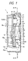
- Fig. 1 is a side sectional view of a gas detecting device 1 for a vehicle according to the preferred embodiment of the present invention
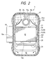
- Fig. 2 is a sectional view taken along line A-A in Fig. 1.
- the gas detecting device 1 detects a gas concentration (a concentration of stinking gas components, such as HC and NOx) in the outside air, and outputs a detection signal indicative of the detected gas concentration to an ECU (electronic control unit) 2 installed in the vehicle as shown in Fig. 3.
- the ECU in response to the detection signal from the gas detecting device 1, outputs a control signal to an actuator 4 for actuating an inside/outside air switching damper 3 of an inside/outside air switching device.
- the inside/outside air switching device includes the inside/outside air switching damper 3 which selectively opens/closes an inside-air introducing port 5a and an outside-air introducing port 5b formed in an inside/outside air switching box 5.
- the inside/outside air switching device further includes the actuator 4, in the form of such as a servomotor, which actuates the inside/outside air switching damper 3.
- the inside/outside air switching box 5 is arranged at an upstream end of a duct 6 which conducts the air toward a vehicle compartment, and is formed integral with a blower case 7a of an air blower 7.
- the gas detecting device 1 is disposed, for example, between a radiator grille (not shown) and a radiator (not shown) of the vehicle and attached to the radiator grille via mounting hooks 8a (see Fig. 1) provided at a front side of a casing 8 of the gas detecting device 1.
- upper and lower directions in Figs. 1 and 2 represent skyward and groundward directions, respectively, of the gas detecting device 1 when mounted on the radiator grille.
- the gas detecting device 1 includes the foregoing casing 8, a separator 9, a filter 10, a gas sensor 11, a circuit board 12 and others.
- the casing 8 is composed of a resinous housing 13 and a resinous cover 14.
- the housing 13 has a box shape and is formed at its lower end with an air introducing passage 15 for introducing the outside air in a backward (rightward in Fig. 1) direction from a front side of the housing 13.
- the air introducing passage 15 has an opening area (cross-sectional area) which is the greatest at an air inlet 15a opened at the front side of the housing 13 and which is then gradually reduced as advancing inward (backward) from the air inlet 15a.
- a passage wall 13a of the housing 13 defining an upper side of the air introducing passage 15 is inclined downward from the air inlet 15a.
- a connector 16 (see Fig. 2) is fixed to a side surface of the housing 13 for connection to the ECU 2.
- the cover 14 is fitted over the outer periphery of the housing 13 and feed to the housing 13 by engagement between claws 13b provided on the outer periphery of the housing 13 and hooks 14a provided on the outer periphery of the cover 14.
- the cover 14 is provided with air outlets 17, a filter pressing portion 18, a presser rib 19 and a water-drip wall 20.
- the air outlets 17 are provided at three locations at each of both upper sides, in a width direction, of the cover 14 as shown in Fig. 2.
- a water-guard wall 21 is provided at each of the air outlets 17 for preventing invasion of moisture or water into the casing 8 through the corresponding air outlet 17.
- the water-guard wall 21 is formed by a portion of the cover 14 which extends inward of the casing 8 in a bent fashion.
- the filter pressing portion 18 is formed by a portion of the cover 14 which is recessed inward at a position below the air outlets 17.
- the filter pressing portion 18 presses and holds an upper side surface 10a of the filter 10 accommodated in the casing 8.
- the presser rib 19 is in the form of an inward projection of the cover 14 and extends vertically below the filter pressing portion 18.
- the presser rib 19 partly presses and holds a lower side surface 10b of the filter 10.
- the water-drip wall 20 is in the form of an inward projection of the cover 14 and extends In the width direction of the cover 14 below the presser rib 19.
- the water-drip wall 20 is provided for achieving a labyrinth structure of a later-described air passage 22.
- the separator 9 is fixed inside the housing 13 via an O-ring 23 interposed between the outer periphery of the separator 9 and the inner periphery of the housing 13.
- the separator 9 divides the inside of the casing 8 into a board side where the circuit board 12 is arranged and a passage side where the introduced outside air flows.
- the air passage 22 is formed between the separator 9 and the cover 14 for communication between the air inlet 15a and the air outlets 17.
- the foregoing air introducing passage 15 forms a portion of the air passage 22.
- the separator 9 is provided with a communication hole 24, drain walls 25 (see Fig. 2), filter supporting sections and a water-drip wall 26.
- the communication hole 24 is formed at an upper center portion of the separator 9 for receiving therethrough the gas sensor 11 so that the gas sensor 11 penetrates from the board side to the passage side.
- the drain walls 25 are provided at right and left sides, in Fig. 2, of the communication hole 24 so as to approach each other as advancing upward. Lower ends of the drain walls 25 extend downward along inner lateral walls of the housing 13.
- the filter supporting sections include four projections 27 which engage an upper end surface 10c and a lower end surface 10d of the filter 10 for positioning the filter 10 in a vertical direction.
- the filter supporting sections further include four lateral walls 28 which engage lateral walls 10e and 10f of the filter 10 for positioning the filter 10 in a lateral or width direction.
- the upper two lateral walls 28 are formed by the portions of the drain walls 25 which extend downward along the inner lateral walls of the housing 13, respectively.
- drain passages 29 are formed at both lateral sides of the filter 10 between the lateral walls 28 and the corresponding inner lateral walls of the housing 13.
- the water-drip wall 26 is in the form of a projection of the separator 9 and extends in the width direction at a vertical position between the presser rib 19 and the water-drip wall 20 of the cover 14.
- the filter 10 is provided for removing dust contained in the introduced outside air.
- the filter 10 is a resilient solid body formed by binding a fibrous material in a known manner and having proper space inside thereof.
- the filter 10 is held in an upright posture at the passage side of the separator 9 by means of the foregoing projections 27 and lateral walls 28, and fixed under pressure between the separator 9 and the cover 14 by means of the filter pressing portion 18 and the presser rib 19.
- the upper side surface 10a of the filter 10 is pressed in its entirety by the filter pressing portion 18, while the lower side surface 10b of the filter 10 is partially pressed by the presser rib 19.
- a certain gap 32 is provided between the lower side surface 10b of the filter 10 and an inner wall surface 8b of the cover 14 due to the presser rib 19 pressing inward the lower side surface 10b of the filter 10.
- the lower end surface 10d and the lower side surface 10b facing the gap 32 are arranged to work as inlet-side air-passing surfaces of the filter 10 where the air flows in, while the upper end surface 10c is arranged to work as an outlet-side air-passing surface where the air flows out.
- a vertical length of the filter 10 (a sum of vertical lengths of the upper and lower side surfaces 10a and 10b) is greater than a sum of lengths of the upper and lower end surfaces 10c and 10d in a right/left direction in Fig. 1.
- the gas sensor 11 includes a detector element (not shown) in the form of a metal oxide semiconductor (for example, formed of SnO2 as a main component added with a small quantity of noble metal), and a heater (not shown) for heating the detector element to high temperatures.
- the detector element has a characteristic to change its electrical resistance when the particular gas components get in touch with a detecting surface 11a thereof while being held at the high temperatures, and outputs a gas concentration in the air in the form of an electric signal (voltage signal). Accordingly, an output voltage variation of the gas sensor 11 is increased as a gas concentration in the air is increased.
- the gas sensor 11 is attached to the circuit board 12 and extends out to the passage side through the communication hole 24 of the separator 9 so that the detecting surface 11a of the detector element is exposed to the air passage 22.
- An air-stay space 30 is formed around the detecting surface 11a so as to allow the air flowing in the air passage 22 to easily stay thereat temporarily.
- the communication hole 24 is hermetically sealed relative to the gas sensor 11 by a grommet 31 mounted on the outer periphery of the gas sensor 11.
- the circuit board 12 includes a signal processing circuit (not shown) for digitizing an analog voltage detection signal from the gas sensor 11 and outputs a digital detection signal digitzed via the signal processing circuit to the ECU 2.
- the circuit board 12 is fixedly disposed in an upright posture at the board side of the separator 9 and connected to built-in terminals (not shown) of the connector 16.
- the outside air introduced into the air introducing passage 15 via the air inlet 15a meanders through the labyrinth structure of the air passage 22.
- the air then passes through the filter 10 where dust contained in the air is removed. Subsequently, the air temporarily stays at the air-stay space 30 and then flows out to the exterior of the casing 8 via the air outlets 17.
- the gas sensor 11 detects a gas concentration in the air staying at the air-stay space 30 and outputs a detection signal indicative of the detected gas concentration to the ECU 2 via the foregoing signal processing circuit of the circuit board 12.
- the given gap 32 is provided between the lower side surface 10b of the filter 10 and the inner wall surface 8b of the cover 14 so that the air having passed through the labyrinth structure of the air passage 22 flows into the filter 10 through both the lower end surface 10d and the lower side surface 10b and then flows out through the upper end surface 10c.
- the air permeability of the filter 10 is ensured to achieve the accurate detection of the gas concentration in the air.
- the air introducing passage 15 has the opening area which is the greatest at the air inlet 15a and then is gradually reduced as advancing inward from the air inlet 15a. Accordingly, a wind velocity of the air introduced via the air inlet 15a is efficiently converted to a pressure within the air introducing passage 15.
- the water-drip walls 20 and 26 forming the labyrinth structure are provided downstream of the filter 10, an air-flow loss can be suppressed due to this conversion to the pressure so that the air can be fed to the gas sensor 11 through the filter 10 in an amount sufficient for detecting the gas concentration.
- the labyrinth structure is provided in the air passage 22 below the filter 10, even when moisture or water is contained in the air introduced via the air introducing passage 15, invasion of the moisture or water can be prevented by the water-drip walls 20 and 26 forming the labyrinth structure. Specifically, when the air containing the moisture or water goes upward to pass through the labyrinth structure, the moisture or water hits the water-drip walls 20 and 26 and falls downward so as to be discharged via the air inlet 15a of the air introducing passage 15.
- the moisture or water reaching the filter 10 can be prevented from diffusing over the entirety of the filter 10 by properly selecting a thickness of the fiber forming the filter 10 and a clogging amount of the filter 10 per unit volume.
- the upper side of the filter 10 is pressed by the filter pressing portion 18 so as to be contracted as a whole in a thickness direction (leftward in Fig. 1), while the lower side of the filter 10 is pressed by the presser rib 19 so as to be partly contracted in the thickness direction so that the other portions thereof are not so contracted.
- meshes of the lower side of the filter 10 are larger (rougher) as compared with those of the upper side of the filter 10.
- This mesh arrangement as well as the foregoing clogging amount selection per unit volume of the filter 10 prevent the moisture or water from diffusing over the entirety of the filter 10. Specifically, since meshes of the filter 10 are larger (rougher) at the lower side thereof as compared with the upper side thereof, the moisture or water in the filter 10 is not liable to go upward and pass through the upper side of the filter 10 for reaching the gas sensor 11, but liable to stay at the lower end portion of the filter 10 due to its own clogging amount.
- the lower end surface 10d of the filter 10 can not be used as an air-passing surface due to formation of the water film, the lower side surface 10b of the filter 10 can be used as an air-passing surface.
- the permeability of the filter 10 is ensured even when the filter 10 is subjected to invasion of the moisture or water so that the normal detection of the gas concentration can be performed using the gas sensor 11.
- the entirety of the gas detecting device 1 is subjected to the moisture or water to allow invasion of the moisture or water into the casing 8 via a gap at the engaging portion between the housing 13 and the cover 14, the invaded moisture or water can be discharged through the drain passages 29 formed at both lateral sides of the filter 10.
- the certain gap 32 is formed between the lower side surface 10b of the filter 10 and the cover 14 for using the lower side surface 10b as an air-passing surface.
- a certain gap may be formed between the separator 9 and a side surface 10g (only at a lower side thereof) of the filter 10 facing the separator 9 so as to use the lower side of the side surface 10g as an air-passing surface, instead of or in addition to the lower side surface 10b.
- the inside/outside air switching device is controlled depending on a gas concentration of the outside air monitored by the gas detecting device 1.
- the gas detecting device 1 is installed in the vehicle compartment to monitor a gas concentration in the inside air (air in the vehicle compartment) and that an air cleaner is controlled to be operated when a degree of contamination of the inside air is high.
- the inside/outside air switching device is controlled to set an outside air mode when a degree of contamination of the inside air is high.
Abstract
Description
- The present invention relates to a gas detecting device installed in a vehicle for detecting a gas concentration in the air.
- A gas detecting device for a vehicle has been proposed such as in Japanese First (unexamined) Utility Model Publication No. 4-72009 and Japanese First (unexamined) Patent Publication No. 4-123919, wherein a gas sensor is received in a casing which forms therein an air passage.
- The gas detecting device of this type is provided with flow-velocity control sections at an inlet and an outlet of the casing for controlling an air-flow velocity at substantially a constant small value. With this arrangement, even when a wind velocity outside the casing changes, a wind velocity within the casing (air passage) can be held substantially constant at a small value. Thus, the gas sensor arranged in the casing can detect a contamination degree of the air reliably without being affected by the wind velocity outside the casing.
- On the other hand, in the foregoing gas detecting device, since the outside air flowing into the casing directly hits the gas sensor, it is highly possible that dust in the air adheres to a detecting surface of the gas sensor and that the detecting surface is subjected to invasion of water or moisture.
- In view of this, it has been proposed to arrange a filter upstream of the gas sensor. The filter has an air-inlet side end surface, an air-outlet side end surface and side surfaces extending along the air passage and connecting the air-inlet side end surface and the air-outlet side end surface to each other. The air is introduced into the air passage via the inlet of the casing and flows into the filter via the air-inlet side end surface and out of the filter via the air-outlet side end surface. When the moisture or water enters the air passage via the inlet of the casing to wet the filter, a water film is likely to be formed at the air-inlet side end surface of the filter so that the air-inlet side end surface of the filter can not be used as an air-passing surface. As a result, the necessary air is not supplied to the gas sensor so that accurate detection of a gas concentration is rendered difficult.
- Therefore, it is an object of the present invention to provide an improved gas detecting device for a vehicle which allows air to pass through a filter and thus achieves accurate detection of a gas concentration in the air even when the filter is subjected to invasion of moisture or water.
- According to one aspect of the present invention, a gas detecting device for a vehicle comprises a casing having therein an air passage, the air passage having an air inlet where air flows in and an air outlet where the air flows out; a filter arranged in the air passage between the air inlet and the air outlet, the filter having a first end surface at a side of the air inlet, a second end surface at a side of the air outlet, and a side surface extending along the air passage and connecting the first and second end surfaces; and a gas sensor for detecting a gas concentration in the air introduced into the air passage through the air inlet and having passed through the filter, wherein a given gap is provided at least between a portion of the side surface located at a side of the first end surface and an inner wall surface of the casing defining the air passage, and wherein the air flows into the filter through the first end surface and the portion of the side surface and flows out of the filter through the second end surface.
- The present invention will be understood more fully from the detailed description given hereinbelow, taken in conjunction with the accompanying drawings.
- In the drawings:
- Fig. 1 is a side sectional view of a gas detecting device for a vehicle according to a preferred embodiment of the present invention;
- Fig. 2 is a sectional view taken along line A-A in Fig. 1; and
- Fig. 3 is a diagram schematically showing an inside/outside air switching device which is operated depending on a gas concentration monitored by the gas detecting device shown in Figs. 1 and 2.
- Now, a preferred embodiment of the present invention will be described hereinbelow with reference to the accompanying drawings.
- Fig. 1 is a side sectional view of a
gas detecting device 1 for a vehicle according to the preferred embodiment of the present invention, and Fig. 2 is a sectional view taken along line A-A in Fig. 1. - The
gas detecting device 1 detects a gas concentration (a concentration of stinking gas components, such as HC and NOx) in the outside air, and outputs a detection signal indicative of the detected gas concentration to an ECU (electronic control unit) 2 installed in the vehicle as shown in Fig. 3. As further shown in Fig. 3, theECU 2, in response to the detection signal from thegas detecting device 1, outputs a control signal to an actuator 4 for actuating an inside/outsideair switching damper 3 of an inside/outside air switching device. - As shown in Fig. 3, the inside/outside air switching device includes the inside/outside
air switching damper 3 which selectively opens/closes an inside-air introducing port 5a and an outside-air introducing port 5b formed in an inside/outsideair switching box 5. The inside/outside air switching device further includes the actuator 4, in the form of such as a servomotor, which actuates the inside/outsideair switching damper 3. The inside/outsideair switching box 5 is arranged at an upstream end of aduct 6 which conducts the air toward a vehicle compartment, and is formed integral with ablower case 7a of anair blower 7. - The
gas detecting device 1 is disposed, for example, between a radiator grille (not shown) and a radiator (not shown) of the vehicle and attached to the radiator grille viamounting hooks 8a (see Fig. 1) provided at a front side of acasing 8 of thegas detecting device 1. - Hereinafter, upper and lower directions in Figs. 1 and 2 represent skyward and groundward directions, respectively, of the
gas detecting device 1 when mounted on the radiator grille. - The
gas detecting device 1 includes theforegoing casing 8, aseparator 9, afilter 10, agas sensor 11, acircuit board 12 and others. - The
casing 8 is composed of aresinous housing 13 and aresinous cover 14. Thehousing 13 has a box shape and is formed at its lower end with anair introducing passage 15 for introducing the outside air in a backward (rightward in Fig. 1) direction from a front side of thehousing 13. - The
air introducing passage 15 has an opening area (cross-sectional area) which is the greatest at anair inlet 15a opened at the front side of thehousing 13 and which is then gradually reduced as advancing inward (backward) from theair inlet 15a. Specifically, apassage wall 13a of thehousing 13 defining an upper side of theair introducing passage 15 is inclined downward from theair inlet 15a. - A connector 16 (see Fig. 2) is fixed to a side surface of the
housing 13 for connection to theECU 2. - The
cover 14 is fitted over the outer periphery of thehousing 13 and feed to thehousing 13 by engagement betweenclaws 13b provided on the outer periphery of thehousing 13 andhooks 14a provided on the outer periphery of thecover 14. - The
cover 14 is provided withair outlets 17, afilter pressing portion 18, apresser rib 19 and a water-drip wall 20. - The
air outlets 17 are provided at three locations at each of both upper sides, in a width direction, of thecover 14 as shown in Fig. 2. A water-guard wall 21 is provided at each of theair outlets 17 for preventing invasion of moisture or water into thecasing 8 through thecorresponding air outlet 17. The water-guard wall 21 is formed by a portion of thecover 14 which extends inward of thecasing 8 in a bent fashion. - The
filter pressing portion 18 is formed by a portion of thecover 14 which is recessed inward at a position below theair outlets 17. Thefilter pressing portion 18 presses and holds anupper side surface 10a of thefilter 10 accommodated in thecasing 8. - The
presser rib 19 is in the form of an inward projection of thecover 14 and extends vertically below thefilter pressing portion 18. Thepresser rib 19 partly presses and holds alower side surface 10b of thefilter 10. - The water-
drip wall 20 is in the form of an inward projection of thecover 14 and extends In the width direction of thecover 14 below thepresser rib 19. The water-drip wall 20 is provided for achieving a labyrinth structure of a later-describedair passage 22. - The
separator 9 is fixed inside thehousing 13 via an O-ring 23 interposed between the outer periphery of theseparator 9 and the inner periphery of thehousing 13. Theseparator 9 divides the inside of thecasing 8 into a board side where thecircuit board 12 is arranged and a passage side where the introduced outside air flows. At the passage side, theair passage 22 is formed between theseparator 9 and thecover 14 for communication between theair inlet 15a and theair outlets 17. The foregoingair introducing passage 15 forms a portion of theair passage 22. - The
separator 9 is provided with acommunication hole 24, drain walls 25 (see Fig. 2), filter supporting sections and a water-drip wall 26. - The
communication hole 24 is formed at an upper center portion of theseparator 9 for receiving therethrough thegas sensor 11 so that thegas sensor 11 penetrates from the board side to the passage side. - The
drain walls 25 are provided at right and left sides, in Fig. 2, of thecommunication hole 24 so as to approach each other as advancing upward. Lower ends of thedrain walls 25 extend downward along inner lateral walls of thehousing 13. - The filter supporting sections include four
projections 27 which engage anupper end surface 10c and alower end surface 10d of thefilter 10 for positioning thefilter 10 in a vertical direction. The filter supporting sections further include fourlateral walls 28 which engagelateral walls filter 10 for positioning thefilter 10 in a lateral or width direction. As seen from Fig. 2, among the fourlateral walls 28, the upper twolateral walls 28 are formed by the portions of thedrain walls 25 which extend downward along the inner lateral walls of thehousing 13, respectively. As further seen from Fig. 2,drain passages 29 are formed at both lateral sides of thefilter 10 between thelateral walls 28 and the corresponding inner lateral walls of thehousing 13. - The water-
drip wall 26 is in the form of a projection of theseparator 9 and extends in the width direction at a vertical position between thepresser rib 19 and the water-drip wall 20 of thecover 14. The water-drip wall 26, in cooperation with the water-drip wall 20, renders theair passage 22 labyrinthine. - The
filter 10 is provided for removing dust contained in the introduced outside air. Thefilter 10 is a resilient solid body formed by binding a fibrous material in a known manner and having proper space inside thereof. Thefilter 10 is held in an upright posture at the passage side of theseparator 9 by means of the foregoingprojections 27 andlateral walls 28, and fixed under pressure between theseparator 9 and thecover 14 by means of thefilter pressing portion 18 and thepresser rib 19. Specifically, theupper side surface 10a of thefilter 10 is pressed in its entirety by thefilter pressing portion 18, while thelower side surface 10b of thefilter 10 is partially pressed by thepresser rib 19. - As shown in Fig. 1, a certain gap 32 is provided between the
lower side surface 10b of thefilter 10 and aninner wall surface 8b of thecover 14 due to thepresser rib 19 pressing inward thelower side surface 10b of thefilter 10. Accordingly, thelower end surface 10d and thelower side surface 10b facing the gap 32 are arranged to work as inlet-side air-passing surfaces of thefilter 10 where the air flows in, while theupper end surface 10c is arranged to work as an outlet-side air-passing surface where the air flows out. As appreciated from Fig. 1, a vertical length of the filter 10 (a sum of vertical lengths of the upper andlower side surfaces - The
gas sensor 11 includes a detector element (not shown) in the form of a metal oxide semiconductor (for example, formed of SnO₂ as a main component added with a small quantity of noble metal), and a heater (not shown) for heating the detector element to high temperatures. The detector element has a characteristic to change its electrical resistance when the particular gas components get in touch with a detectingsurface 11a thereof while being held at the high temperatures, and outputs a gas concentration in the air in the form of an electric signal (voltage signal). Accordingly, an output voltage variation of thegas sensor 11 is increased as a gas concentration in the air is increased. - The
gas sensor 11 is attached to thecircuit board 12 and extends out to the passage side through thecommunication hole 24 of theseparator 9 so that the detectingsurface 11a of the detector element is exposed to theair passage 22. An air-stay space 30 is formed around the detectingsurface 11a so as to allow the air flowing in theair passage 22 to easily stay thereat temporarily. - The
communication hole 24 is hermetically sealed relative to thegas sensor 11 by agrommet 31 mounted on the outer periphery of thegas sensor 11. - The
circuit board 12 includes a signal processing circuit (not shown) for digitizing an analog voltage detection signal from thegas sensor 11 and outputs a digital detection signal digitzed via the signal processing circuit to theECU 2. Thecircuit board 12 is fixedly disposed in an upright posture at the board side of theseparator 9 and connected to built-in terminals (not shown) of theconnector 16. - Now, an operation of this embodiment will be described hereinbelow.
- The outside air introduced into the
air introducing passage 15 via theair inlet 15a meanders through the labyrinth structure of theair passage 22. The air then passes through thefilter 10 where dust contained in the air is removed. Subsequently, the air temporarily stays at the air-stay space 30 and then flows out to the exterior of thecasing 8 via theair outlets 17. Thegas sensor 11 detects a gas concentration in the air staying at the air-stay space 30 and outputs a detection signal indicative of the detected gas concentration to theECU 2 via the foregoing signal processing circuit of thecircuit board 12. - In this embodiment, as described before, the given gap 32 is provided between the
lower side surface 10b of thefilter 10 and theinner wall surface 8b of thecover 14 so that the air having passed through the labyrinth structure of theair passage 22 flows into thefilter 10 through both thelower end surface 10d and thelower side surface 10b and then flows out through theupper end surface 10c. Thus, even when moisture or water enters theair passage 22 via theair inlet 15a to moisten or wet thefilter 10 so that a water film is formed at thelower end surface 10d to disable the air from entering thefilter 10 via thelower end surface 10d, the air still can be introduced into thefilter 10 via thelower side surface 10b. Accordingly, the air permeability of thefilter 10 is ensured to achieve the accurate detection of the gas concentration in the air. - Further, as described before, the
air introducing passage 15 has the opening area which is the greatest at theair inlet 15a and then is gradually reduced as advancing inward from theair inlet 15a. Accordingly, a wind velocity of the air introduced via theair inlet 15a is efficiently converted to a pressure within theair introducing passage 15. Thus, even if the water-drip walls filter 10, an air-flow loss can be suppressed due to this conversion to the pressure so that the air can be fed to thegas sensor 11 through thefilter 10 in an amount sufficient for detecting the gas concentration. - Further, since the labyrinth structure is provided in the
air passage 22 below thefilter 10, even when moisture or water is contained in the air introduced via theair introducing passage 15, invasion of the moisture or water can be prevented by the water-drip walls drip walls air inlet 15a of theair introducing passage 15. - On the other hand, the moisture or water reaching the
filter 10 can be prevented from diffusing over the entirety of thefilter 10 by properly selecting a thickness of the fiber forming thefilter 10 and a clogging amount of thefilter 10 per unit volume. In this embodiment, the upper side of thefilter 10 is pressed by thefilter pressing portion 18 so as to be contracted as a whole in a thickness direction (leftward in Fig. 1), while the lower side of thefilter 10 is pressed by thepresser rib 19 so as to be partly contracted in the thickness direction so that the other portions thereof are not so contracted. Thus, meshes of the lower side of thefilter 10 are larger (rougher) as compared with those of the upper side of thefilter 10. This mesh arrangement as well as the foregoing clogging amount selection per unit volume of thefilter 10 prevent the moisture or water from diffusing over the entirety of thefilter 10. Specifically, since meshes of thefilter 10 are larger (rougher) at the lower side thereof as compared with the upper side thereof, the moisture or water in thefilter 10 is not liable to go upward and pass through the upper side of thefilter 10 for reaching thegas sensor 11, but liable to stay at the lower end portion of thefilter 10 due to its own clogging amount. - When a quantity of the moisture or water staying at the lower end portion of the
filter 10 is increased, the moisture or water drips down and flows out via theair inlet 15a. Accordingly, although thelower end surface 10d of thefilter 10 can not be used as an air-passing surface due to formation of the water film, thelower side surface 10b of thefilter 10 can be used as an air-passing surface. Thus, the permeability of thefilter 10 is ensured even when thefilter 10 is subjected to invasion of the moisture or water so that the normal detection of the gas concentration can be performed using thegas sensor 11. - Further, if the entirety of the
gas detecting device 1 is subjected to the moisture or water to allow invasion of the moisture or water into thecasing 8 via a gap at the engaging portion between thehousing 13 and thecover 14, the invaded moisture or water can be discharged through thedrain passages 29 formed at both lateral sides of thefilter 10. - On the other hand, when the
air outlets 17 are subjected to the moisture or water, invasion of the moisture or water into thecasing 8 can be prevented by the water-guard walls 21. Further, even if the moisture or water enters thecasing 8 via theair outlets 17 and the water-guard walls 21, the invaded moisture or water is received by thedrain walls 25 and guided to thedrain passages 29 so that thegas sensor 11 is prevented from being subjected to the moisture or water. - In the foregoing preferred embodiment, the certain gap 32 is formed between the
lower side surface 10b of thefilter 10 and thecover 14 for using thelower side surface 10b as an air-passing surface. On the other hand, a certain gap may be formed between theseparator 9 and aside surface 10g (only at a lower side thereof) of thefilter 10 facing theseparator 9 so as to use the lower side of theside surface 10g as an air-passing surface, instead of or in addition to thelower side surface 10b. - Further, in the foregoing preferred embodiment, the inside/outside air switching device is controlled depending on a gas concentration of the outside air monitored by the
gas detecting device 1. On the other hand, it may also be arranged that thegas detecting device 1 is installed in the vehicle compartment to monitor a gas concentration in the inside air (air in the vehicle compartment) and that an air cleaner is controlled to be operated when a degree of contamination of the inside air is high. Alternatively, it may also be arranged that the inside/outside air switching device is controlled to set an outside air mode when a degree of contamination of the inside air is high. - While the present invention has been described in terms of the preferred embodiment, the invention is not to be limited thereto, but can be embodied in various ways without departing from the principle of the invention as defined in the appended claims.
Claims (7)
- A gas detecting device for a vehicle comprising:
a casing having therein an air passage, said air passage having an air inlet where air flows in and an air outlet where the air flows out;
a filter arranged in said air passage between said air inlet and said air outlet, said filter having a first end surface at a side of said air inlet, a second end surface at a side of said air outlet, and a side surface extending along said air passage and connecting said first and second end surfaces; and
a gas sensor for detecting a gas concentration in the air introduced into said air passage through said air inlet and having passed through said filter;
wherein a given gap is provided at least between a portion of said side surface located at a side of said first end surface and an inner wall surface of said casing defining said air passage, and wherein the air flows into said filter through said first end surface and said portion of the side surface and flows out of said filter through said second end surface. - The gas detecting device according to claim 1, wherein said first end surface of the filter is arranged at a position below said second end surface of the filter.
- The gas detecting device according to claim 1, wherein meshes of said filter are larger at the side of said first end surface than at a side of said second end surface.
- The gas detecting device according to claim 1, wherein a labyrinth structure is provided in said air passage between said air inlet and said filter for suppressing invasion of moisture or water through said air inlet.
- The gas detecting device according to claim 4, wherein said air passage has an air introducing section extending between said air inlet and said labyrinth structure, said air introducing section having an opening area which is the greatest at said air inlet and is gradually reduced as advancing toward said labyrinth structure.
- The gas detecting device according to claim 1, wherein said casing is provided therein with a drain passage and a drain wall for guiding moisture or water entering said casing through said air outlet to said drain passage.
- The gas detecting device according to claim 6, wherein a detecting surface of said gas sensor is exposed within said air passage between said filter and said air outlet, and wherein said drain wall is provided between said air outlet and said detecting surface of the gas sensor and extends to said drain passage.
Applications Claiming Priority (4)
| Application Number | Priority Date | Filing Date | Title |
|---|---|---|---|
| JP28316694 | 1994-11-17 | ||
| JP283166/94 | 1994-11-17 | ||
| JP215632/95 | 1995-08-24 | ||
| JP21563295A JP3627306B2 (en) | 1994-11-17 | 1995-08-24 | Gas detector for vehicles |
Publications (2)
| Publication Number | Publication Date |
|---|---|
| EP0712745A1 true EP0712745A1 (en) | 1996-05-22 |
| EP0712745B1 EP0712745B1 (en) | 1999-03-10 |
Family
ID=26520971
Family Applications (1)
| Application Number | Title | Priority Date | Filing Date |
|---|---|---|---|
| EP95117699A Expired - Lifetime EP0712745B1 (en) | 1994-11-17 | 1995-11-09 | Gas detecting device for vehicle |
Country Status (4)
| Country | Link |
|---|---|
| US (1) | US5624639A (en) |
| EP (1) | EP0712745B1 (en) |
| JP (1) | JP3627306B2 (en) |
| DE (1) | DE69508186T2 (en) |
Cited By (5)
| Publication number | Priority date | Publication date | Assignee | Title |
|---|---|---|---|---|
| EP0779170A2 (en) | 1995-12-15 | 1997-06-18 | paragon sensoric GmbH & Co. KG | Pollutant detector |
| EP1031833A2 (en) * | 1999-02-22 | 2000-08-30 | Ngk Spark Plug Co., Ltd | Gas sensor device |
| EP1146336A2 (en) * | 2000-04-13 | 2001-10-17 | MSA Auer GmbH | Gas sensing apparatus |
| EP1630553A1 (en) | 2004-08-19 | 2006-03-01 | NGK Spark Plug Co., Ltd. | Gas sensor unit |
| WO2006121321A1 (en) * | 2005-05-10 | 2006-11-16 | Sensata Technologies Holland B.V. | Sensor module package |
Families Citing this family (13)
| Publication number | Priority date | Publication date | Assignee | Title |
|---|---|---|---|---|
| JPH11321289A (en) * | 1998-05-08 | 1999-11-24 | Zexel:Kk | Air conditioning system for motor vehicle |
| JP2942256B1 (en) * | 1998-09-28 | 1999-08-30 | 株式会社ゼクセル | Vehicle gas detector |
| JP4533557B2 (en) * | 2001-05-25 | 2010-09-01 | 三菱重工業株式会社 | Gas detector and air conditioner using the same |
| KR100431934B1 (en) * | 2001-07-28 | 2004-05-17 | 씨멘스브이디오한라 주식회사 | Sensing apparatus for harmful gas |
| JP4167008B2 (en) * | 2002-05-24 | 2008-10-15 | 日本特殊陶業株式会社 | Gas detector |
| WO2004111627A1 (en) * | 2003-06-12 | 2004-12-23 | Fis Inc. | Automobile gas detector |
| US7712349B2 (en) | 2003-12-01 | 2010-05-11 | Ngk Spark Plug Co., Ltd. | Gas sensor |
| JP4728071B2 (en) * | 2005-09-05 | 2011-07-20 | 日本特殊陶業株式会社 | Gas detector |
| JP4774110B2 (en) * | 2008-07-28 | 2011-09-14 | 日本特殊陶業株式会社 | Circuit board case |
| US20180339258A1 (en) * | 2017-05-29 | 2018-11-29 | Pil-Dong Jeon | Air cleaning apparatus with a moist filter |
| EP3657080A4 (en) * | 2017-07-21 | 2020-08-05 | Mitsubishi Electric Corporation | Air conditioner |
| JP6758435B2 (en) * | 2019-01-21 | 2020-09-23 | 三菱電機株式会社 | Air conditioner |
| US11813558B2 (en) | 2022-04-08 | 2023-11-14 | Honda Motor Co., Ltd. | Atmospheric box |
Citations (4)
| Publication number | Priority date | Publication date | Assignee | Title |
|---|---|---|---|---|
| US5059221A (en) * | 1989-08-15 | 1991-10-22 | Siemens-Bendix Automotive Electronics Limited | Integrated air cleaner assembly |
| JPH04123919A (en) | 1990-09-14 | 1992-04-23 | Zexel Corp | Gas detecting device in air conditioner for vehicle |
| JPH0472009U (en) | 1990-11-07 | 1992-06-25 | ||
| DE9110325U1 (en) * | 1991-08-21 | 1992-12-17 | Robert Bosch Gmbh, 7000 Stuttgart, De |
Family Cites Families (10)
| Publication number | Priority date | Publication date | Assignee | Title |
|---|---|---|---|---|
| RO55240A2 (en) * | 1970-05-13 | 1973-05-17 | ||
| US4170455A (en) * | 1976-03-11 | 1979-10-09 | Rockwell International Corporation | Gas monitoring method and apparatus therefor |
| JPS59174906U (en) * | 1983-05-11 | 1984-11-22 | クラリオン株式会社 | Automatic air adjustment device for vehicles |
| JPS60115112U (en) * | 1984-01-12 | 1985-08-03 | 三菱自動車工業株式会社 | Vehicle air conditioner |
| US4665690A (en) * | 1985-01-14 | 1987-05-19 | Mazda Motor Corporation | Exhaust gas cleaning system for vehicle |
| GB8520273D0 (en) * | 1985-08-13 | 1985-09-18 | Smidth & Co As F L | Extracting sample from gas flow |
| US5314828A (en) * | 1990-06-12 | 1994-05-24 | Catalytica, Inc. | NOx sensor and process for detecting NOx |
| JPH0472009A (en) * | 1990-07-10 | 1992-03-06 | Kawasaki Steel Corp | Method for refining high cleanliness steel |
| JPH0763647B2 (en) * | 1990-08-17 | 1995-07-12 | 松下電器産業株式会社 | Automotive air purifier |
| US5320577A (en) * | 1993-03-22 | 1994-06-14 | Figaro Engineering Inc. | Air conditioner control device |
-
1995
- 1995-08-24 JP JP21563295A patent/JP3627306B2/en not_active Expired - Fee Related
- 1995-11-09 DE DE69508186T patent/DE69508186T2/en not_active Expired - Lifetime
- 1995-11-09 EP EP95117699A patent/EP0712745B1/en not_active Expired - Lifetime
- 1995-11-16 US US08/559,097 patent/US5624639A/en not_active Expired - Lifetime
Patent Citations (4)
| Publication number | Priority date | Publication date | Assignee | Title |
|---|---|---|---|---|
| US5059221A (en) * | 1989-08-15 | 1991-10-22 | Siemens-Bendix Automotive Electronics Limited | Integrated air cleaner assembly |
| JPH04123919A (en) | 1990-09-14 | 1992-04-23 | Zexel Corp | Gas detecting device in air conditioner for vehicle |
| JPH0472009U (en) | 1990-11-07 | 1992-06-25 | ||
| DE9110325U1 (en) * | 1991-08-21 | 1992-12-17 | Robert Bosch Gmbh, 7000 Stuttgart, De |
Non-Patent Citations (1)
| Title |
|---|
| PATENT ABSTRACTS OF JAPAN vol. 16, no. 380 (M - 1295) * |
Cited By (9)
| Publication number | Priority date | Publication date | Assignee | Title |
|---|---|---|---|---|
| EP0779170A2 (en) | 1995-12-15 | 1997-06-18 | paragon sensoric GmbH & Co. KG | Pollutant detector |
| EP0779170A3 (en) * | 1995-12-15 | 1999-01-13 | paragon sensoric GmbH & Co. KG | Pollutant detector |
| EP1031833A2 (en) * | 1999-02-22 | 2000-08-30 | Ngk Spark Plug Co., Ltd | Gas sensor device |
| EP1031833A3 (en) * | 1999-02-22 | 2002-04-03 | Ngk Spark Plug Co., Ltd | Gas sensor device |
| US6453723B1 (en) | 1999-02-22 | 2002-09-24 | Ngk Spark Plug Co., Ltd. | Gas sensor device |
| EP1146336A2 (en) * | 2000-04-13 | 2001-10-17 | MSA Auer GmbH | Gas sensing apparatus |
| EP1146336A3 (en) * | 2000-04-13 | 2003-12-10 | MSA Auer GmbH | Gas sensing apparatus |
| EP1630553A1 (en) | 2004-08-19 | 2006-03-01 | NGK Spark Plug Co., Ltd. | Gas sensor unit |
| WO2006121321A1 (en) * | 2005-05-10 | 2006-11-16 | Sensata Technologies Holland B.V. | Sensor module package |
Also Published As
| Publication number | Publication date |
|---|---|
| JPH08192617A (en) | 1996-07-30 |
| US5624639A (en) | 1997-04-29 |
| EP0712745B1 (en) | 1999-03-10 |
| DE69508186T2 (en) | 1999-10-14 |
| JP3627306B2 (en) | 2005-03-09 |
| DE69508186D1 (en) | 1999-04-15 |
Similar Documents
| Publication | Publication Date | Title |
|---|---|---|
| US5624639A (en) | Gas detecting device for vehicle | |
| JP5135469B2 (en) | In-vehicle air conditioner equipped with filter element with humidity sensor and operation method thereof | |
| US6206775B1 (en) | Motor vehicle heating and/or air conditioning device comprising a pollution sensor | |
| KR100967762B1 (en) | Filter arrangement | |
| EP0770348B1 (en) | Cooling arrangement for power components in a vacuum cleaner | |
| KR20000023240A (en) | Device for controlling the indoor-temperature in the passenger compartment of a motor vehicle | |
| WO2013051488A1 (en) | Humidity detection device | |
| JP3587326B2 (en) | Gas detector | |
| JP2007071604A (en) | Gas detector | |
| EP1054313B1 (en) | Temperature sensor | |
| KR200367856Y1 (en) | Sensor assembly for air conditioning system | |
| EP0693659A3 (en) | Curative air conditioner | |
| US5625346A (en) | Enhanced capabilities of smoke detectors | |
| JP2003525527A (en) | Device for cooling electrical components and components of the device | |
| CN115902125A (en) | Double-channel gas sensor | |
| JP4133505B2 (en) | Gas sensor unit | |
| JP5064318B2 (en) | Sensor module mounting structure | |
| JP2000351312A (en) | Temperature and humidity detection device for vehicle | |
| JP2002318216A (en) | Gas sensor | |
| CN219868439U (en) | Air conditioner | |
| CN219495339U (en) | Flow sensor module and flowmeter | |
| JP4150986B2 (en) | Integrated sensor | |
| JP2004085265A (en) | Windowpane with condensation sensor | |
| JP2003344339A (en) | Gas sensor | |
| JP4033121B2 (en) | Outdoor unit of separate air conditioner |
Legal Events
| Date | Code | Title | Description |
|---|---|---|---|
| PUAI | Public reference made under article 153(3) epc to a published international application that has entered the european phase |
Free format text: ORIGINAL CODE: 0009012 |
|
| AK | Designated contracting states |
Kind code of ref document: A1 Designated state(s): DE FR GB |
|
| 17P | Request for examination filed |
Effective date: 19960529 |
|
| 17Q | First examination report despatched |
Effective date: 19970513 |
|
| RAP1 | Party data changed (applicant data changed or rights of an application transferred) |
Owner name: DENSO CORPORATION |
|
| GRAG | Despatch of communication of intention to grant |
Free format text: ORIGINAL CODE: EPIDOS AGRA |
|
| GRAG | Despatch of communication of intention to grant |
Free format text: ORIGINAL CODE: EPIDOS AGRA |
|
| GRAH | Despatch of communication of intention to grant a patent |
Free format text: ORIGINAL CODE: EPIDOS IGRA |
|
| GRAH | Despatch of communication of intention to grant a patent |
Free format text: ORIGINAL CODE: EPIDOS IGRA |
|
| GRAA | (expected) grant |
Free format text: ORIGINAL CODE: 0009210 |
|
| AK | Designated contracting states |
Kind code of ref document: B1 Designated state(s): DE FR GB |
|
| REF | Corresponds to: |
Ref document number: 69508186 Country of ref document: DE Date of ref document: 19990415 |
|
| ET | Fr: translation filed | ||
| PLBE | No opposition filed within time limit |
Free format text: ORIGINAL CODE: 0009261 |
|
| STAA | Information on the status of an ep patent application or granted ep patent |
Free format text: STATUS: NO OPPOSITION FILED WITHIN TIME LIMIT |
|
| 26N | No opposition filed | ||
| REG | Reference to a national code |
Ref country code: GB Ref legal event code: IF02 |
|
| PGFP | Annual fee paid to national office [announced via postgrant information from national office to epo] |
Ref country code: FR Payment date: 20101123 Year of fee payment: 16 |
|
| PGFP | Annual fee paid to national office [announced via postgrant information from national office to epo] |
Ref country code: GB Payment date: 20101103 Year of fee payment: 16 |
|
| GBPC | Gb: european patent ceased through non-payment of renewal fee |
Effective date: 20111109 |
|
| REG | Reference to a national code |
Ref country code: FR Ref legal event code: ST Effective date: 20120731 |
|
| PG25 | Lapsed in a contracting state [announced via postgrant information from national office to epo] |
Ref country code: GB Free format text: LAPSE BECAUSE OF NON-PAYMENT OF DUE FEES Effective date: 20111109 |
|
| PG25 | Lapsed in a contracting state [announced via postgrant information from national office to epo] |
Ref country code: FR Free format text: LAPSE BECAUSE OF NON-PAYMENT OF DUE FEES Effective date: 20111130 |
|
| PGFP | Annual fee paid to national office [announced via postgrant information from national office to epo] |
Ref country code: DE Payment date: 20131121 Year of fee payment: 19 |
|
| REG | Reference to a national code |
Ref country code: DE Ref legal event code: R119 Ref document number: 69508186 Country of ref document: DE |
|
| PG25 | Lapsed in a contracting state [announced via postgrant information from national office to epo] |
Ref country code: DE Free format text: LAPSE BECAUSE OF NON-PAYMENT OF DUE FEES Effective date: 20150602 |