EP0710811B2 - An automobile air conditioning system - Google Patents
An automobile air conditioning system Download PDFInfo
- Publication number
- EP0710811B2 EP0710811B2 EP95117346A EP95117346A EP0710811B2 EP 0710811 B2 EP0710811 B2 EP 0710811B2 EP 95117346 A EP95117346 A EP 95117346A EP 95117346 A EP95117346 A EP 95117346A EP 0710811 B2 EP0710811 B2 EP 0710811B2
- Authority
- EP
- European Patent Office
- Prior art keywords
- hot water
- heat exchanger
- flat tubes
- core portion
- tank
- Prior art date
- Legal status (The legal status is an assumption and is not a legal conclusion. Google has not performed a legal analysis and makes no representation as to the accuracy of the status listed.)
- Expired - Lifetime
Links
Images


Classifications
-
- F—MECHANICAL ENGINEERING; LIGHTING; HEATING; WEAPONS; BLASTING
- F28—HEAT EXCHANGE IN GENERAL
- F28D—HEAT-EXCHANGE APPARATUS, NOT PROVIDED FOR IN ANOTHER SUBCLASS, IN WHICH THE HEAT-EXCHANGE MEDIA DO NOT COME INTO DIRECT CONTACT
- F28D1/00—Heat-exchange apparatus having stationary conduit assemblies for one heat-exchange medium only, the media being in contact with different sides of the conduit wall, in which the other heat-exchange medium is a large body of fluid, e.g. domestic or motor car radiators
-
- F—MECHANICAL ENGINEERING; LIGHTING; HEATING; WEAPONS; BLASTING
- F28—HEAT EXCHANGE IN GENERAL
- F28F—DETAILS OF HEAT-EXCHANGE AND HEAT-TRANSFER APPARATUS, OF GENERAL APPLICATION
- F28F1/00—Tubular elements; Assemblies of tubular elements
- F28F1/10—Tubular elements and assemblies thereof with means for increasing heat-transfer area, e.g. with fins, with projections, with recesses
- F28F1/12—Tubular elements and assemblies thereof with means for increasing heat-transfer area, e.g. with fins, with projections, with recesses the means being only outside the tubular element
- F28F1/126—Tubular elements and assemblies thereof with means for increasing heat-transfer area, e.g. with fins, with projections, with recesses the means being only outside the tubular element consisting of zig-zag shaped fins
-
- F—MECHANICAL ENGINEERING; LIGHTING; HEATING; WEAPONS; BLASTING
- F28—HEAT EXCHANGE IN GENERAL
- F28D—HEAT-EXCHANGE APPARATUS, NOT PROVIDED FOR IN ANOTHER SUBCLASS, IN WHICH THE HEAT-EXCHANGE MEDIA DO NOT COME INTO DIRECT CONTACT
- F28D1/00—Heat-exchange apparatus having stationary conduit assemblies for one heat-exchange medium only, the media being in contact with different sides of the conduit wall, in which the other heat-exchange medium is a large body of fluid, e.g. domestic or motor car radiators
- F28D1/02—Heat-exchange apparatus having stationary conduit assemblies for one heat-exchange medium only, the media being in contact with different sides of the conduit wall, in which the other heat-exchange medium is a large body of fluid, e.g. domestic or motor car radiators with heat-exchange conduits immersed in the body of fluid
- F28D1/04—Heat-exchange apparatus having stationary conduit assemblies for one heat-exchange medium only, the media being in contact with different sides of the conduit wall, in which the other heat-exchange medium is a large body of fluid, e.g. domestic or motor car radiators with heat-exchange conduits immersed in the body of fluid with tubular conduits
- F28D1/053—Heat-exchange apparatus having stationary conduit assemblies for one heat-exchange medium only, the media being in contact with different sides of the conduit wall, in which the other heat-exchange medium is a large body of fluid, e.g. domestic or motor car radiators with heat-exchange conduits immersed in the body of fluid with tubular conduits the conduits being straight
- F28D1/0535—Heat-exchange apparatus having stationary conduit assemblies for one heat-exchange medium only, the media being in contact with different sides of the conduit wall, in which the other heat-exchange medium is a large body of fluid, e.g. domestic or motor car radiators with heat-exchange conduits immersed in the body of fluid with tubular conduits the conduits being straight the conduits having a non-circular cross-section
- F28D1/05366—Assemblies of conduits connected to common headers, e.g. core type radiators
-
- F—MECHANICAL ENGINEERING; LIGHTING; HEATING; WEAPONS; BLASTING
- F28—HEAT EXCHANGE IN GENERAL
- F28F—DETAILS OF HEAT-EXCHANGE AND HEAT-TRANSFER APPARATUS, OF GENERAL APPLICATION
- F28F1/00—Tubular elements; Assemblies of tubular elements
- F28F1/10—Tubular elements and assemblies thereof with means for increasing heat-transfer area, e.g. with fins, with projections, with recesses
- F28F1/12—Tubular elements and assemblies thereof with means for increasing heat-transfer area, e.g. with fins, with projections, with recesses the means being only outside the tubular element
-
- F—MECHANICAL ENGINEERING; LIGHTING; HEATING; WEAPONS; BLASTING
- F28—HEAT EXCHANGE IN GENERAL
- F28F—DETAILS OF HEAT-EXCHANGE AND HEAT-TRANSFER APPARATUS, OF GENERAL APPLICATION
- F28F21/00—Constructions of heat-exchange apparatus characterised by the selection of particular materials
- F28F21/08—Constructions of heat-exchange apparatus characterised by the selection of particular materials of metal
- F28F21/081—Heat exchange elements made from metals or metal alloys
- F28F21/084—Heat exchange elements made from metals or metal alloys from aluminium or aluminium alloys
-
- Y—GENERAL TAGGING OF NEW TECHNOLOGICAL DEVELOPMENTS; GENERAL TAGGING OF CROSS-SECTIONAL TECHNOLOGIES SPANNING OVER SEVERAL SECTIONS OF THE IPC; TECHNICAL SUBJECTS COVERED BY FORMER USPC CROSS-REFERENCE ART COLLECTIONS [XRACs] AND DIGESTS
- Y10—TECHNICAL SUBJECTS COVERED BY FORMER USPC
- Y10S—TECHNICAL SUBJECTS COVERED BY FORMER USPC CROSS-REFERENCE ART COLLECTIONS [XRACs] AND DIGESTS
- Y10S165/00—Heat exchange
- Y10S165/454—Heat exchange having side-by-side conduits structure or conduit section
- Y10S165/471—Plural parallel conduits joined by manifold
- Y10S165/486—Corrugated fins disposed between adjacent conduits
- Y10S165/487—Louvered
-
- Y—GENERAL TAGGING OF NEW TECHNOLOGICAL DEVELOPMENTS; GENERAL TAGGING OF CROSS-SECTIONAL TECHNOLOGIES SPANNING OVER SEVERAL SECTIONS OF THE IPC; TECHNICAL SUBJECTS COVERED BY FORMER USPC CROSS-REFERENCE ART COLLECTIONS [XRACs] AND DIGESTS
- Y10—TECHNICAL SUBJECTS COVERED BY FORMER USPC
- Y10S—TECHNICAL SUBJECTS COVERED BY FORMER USPC CROSS-REFERENCE ART COLLECTIONS [XRACs] AND DIGESTS
- Y10S165/00—Heat exchange
- Y10S165/454—Heat exchange having side-by-side conduits structure or conduit section
- Y10S165/50—Side-by-side conduits with fins
- Y10S165/505—Corrugated strips disposed between adjacent conduits
Definitions
- the present invention relates to an automotive air conditioning system according to the preamble of claim 1.
- US 5,311,935 discloses such a heat exchanger in which hot water flows from the inlet pipe through tubes downwardly, and then passes through other tubes upwardly after being U-turned at the undermost part of the tubes. Subsequently the hot water is discharged through an outlet pipe.
- the present invention is preferably applied to an automotive air conditioner in which hot water flow quantity widely varies.
- a conventional heat exchanger 2 for heating is installed in a cooling water (hot water) circuit of an engine 1 for running the vehicle.
- Hot water is circulated into the heat exchanger 2 by a water pump 3 driven by the engine 1, and the flow quantity of the hot water flowing from a flow quantity control valve 4 into the heat exchange 2 is controlled to adjust the temperature of the air flow of the heat exchanger 2.
- Engine cooling water is circulated into a radiator 6 by the water pump 3 through a thermostat 5 to cool the engine cooling water within the radiator 6.
- the thermostat is a well-known device, in which a valve opens when the cooling water temperature rises to or exceeds a predetermined temperature, thereby the cooling water flowing into the radiator 6.
- the reference numeral 7 denotes a bypass circuit for the engine cooling water
- 8 denotes a radiator side circuit
- 9 denotes a heater side circuit.
- the water pump 3 circulates the cooling water through all these circuits 7, 8 and 9.
- a rotational speed of the water pump 3 largely varies according to the rotational speed of the engine 1, i.e., the vehicle speed, and thereby flow quantity of the hot water into the heat exchanger 2 largely varies.
- the ordinate represents the heat radiation performance Q of the heat exchanger 2
- the abscissa represents the flow quantity Vw of the hot water into the heat exchanger 2.
- the hot water flow quantity is 16 lit/min when the vehicle is running at 60 km/h
- the hot water flow quantity is 4 lit/min when the vehicle is in idling.
- the heat radiation performance when the vehicle is in idling falls by 22 % down as compared to when the vehicle is running at 60 km/h. As a result, heating feeling is deteriorated.
- the inventors of the present invention have studied the cause of such deterioration of the heat radiation performance from various points of view and found out the following reasons.
- the heat exchanger 2 includes a plurality of flat tubes 2a arranged in parallel with the air flow direction. These flat tubes 2a are individually disposed in a single row. Corrugate fins 2b are disposed between each pair of flat tubes 2a, thereby configuring a corrugate type heat exchanger.
- the reference numeral 2c denotes a core portion which is composed of the flat tubes 2a and the corrugate fins 2b.
- the ordinate represents water side heat transfer rate ⁇ w of the flat tube 2a
- the abscissa represents the Reynold's number Re and hot water flow quantity Vw of the hot water passages formed with the flat tubes 2a.
- the Reynold's number is within a range of 500 - 2200 when the hot water flowing into the heat exchanger 2 is within a predetermined range (16 lit/min when the vehicle is running at 60 km/h, and 4 lit/min when the vehicle is in idling), and the heat exchanger 2 is operated to the extent from the laminar region to a transition flow region.
- the water side heat transfer rate ⁇ w largely varies in accordance with the variation of the hot water flow quantity.
- it turned out that the water side heat transfer rate ⁇ w largely falls within the low flow quantity region, thereby causing the deterioration of the heat radiation performance when the vehicle is in idling.
- FIG. 4 illustrates the results of an experiment in which normal tubes with no dimples (concave and convex portion) for facilitating the turbulence of the hot water on the inner surfaces were used as the flat tubes 2a.
- a turbulence generator for facilitating turbulence is inserted into the tubes or dimples for facilitating turbulence is formed on the inner surfaces of the tubes.
- the inventors of the present invention have measured the water side heat transfer rate ⁇ w by using the flat tubes 2a with dimples for facilitating turbulence.
- the flat tube with dimples could generally improve the water side heat transfer rate ⁇ w as compared to the normal tube, and the Reynold's number Re of the dimple tube in the transition region from laminar to turbulence decreased from 1400 with the normal tube to 1000.
- the present invention has an object to provide an air conditioning system which can effectively improve the heat radiation performance within a low flow quantity region.
- the Reynold's number of the flow passages of the flat tubes is set to be extremely small to keep water flow in the flow passages of the flat tubes in a complete laminar region over the regular use range of the hot water flow quantity from the high flow quantity region to the low flow quantity region, thereby reducing the variation in the water side heat transfer rate ⁇ w and increasing the water side heat transfer rate ⁇ w simultaneously to improve the heat radiation performance with the low flow quantity region.
- the Reynold's number is set to 1000 or less when flow quantity of the hot water passing through the core portion is 16 lit/min.
- the height Hf of a corrugate fin 2b is set in a range of 3 - 6 mm with 4.5 mm in the center, in consideration of the heat radiation performance, which is described in US 5, 311, 935.
- the flow velocity v of hot water within the flat tubes 2a and the equivalent diameter de of the flat tube 2a should be reduced by using the following equation (1).
- Re v ⁇ de / ⁇
- ⁇ is the kinematic viscosity of the hot water within the flat tubes 2a
- the substantial round-hole diameter de of the flat tube 2a is the diameter of the round-hole having the same area as the cross-sectional area of the flat tube 2a.
- the total area St of the flow passages of the flat tubes 2a should be increased by using the following equation (2).
- Vw is the flow quantity of the hot water flowing into the heat exchanger 2
- St is the sum total of the cross-sectional areas of the flow passages within all the flat tubes 2a of the core portion 2c.
- the cross-sectional area A of the flow passage per flat tube 2a should be reduced by using the following equation 3.
- de 4 ⁇ A / L
- L is the wet edge length within the flat tube 2a (the length of the inner peripheral wall of the cross-sectional shape of the flat tube 2a, which will be described later with reference to FIGS. 7 and 8 ).
- a liquid mixture of an antifreeze solution containing a rust preventive and water combined at approximately 50:50 is generally used for the hot water (engine cooling water) circulating into the heat exchanger 2, and the hot water temperature is maintained to approximately 85° C by the thermostat 5.
- the core portion 2c should be an one way flow type (full-pass type) having the cross-sectional area (W ⁇ D) of the core portion 2c in which the hot water flows only in one direction instead of U-turn type in which the hot water flows in a U-turn, and the number of the flat tubes 2a having the cross-sectional area (W ⁇ D) of the core portion 2c, through which the hot water flows in parallel, should be increased.
- the concrete structure of the core portion 2c of the one way flow type (full-pass type) will be described later with reference to FIG. 15 .
- the inventor of the present invention examined the total cross-sectional flow passage area St of the flat tubes 2a which could hold the Reynold's number Re to be 1000 or less (within the complete laminar region in FIG. 5 ) until the hot water flow quantity Vw increases to 16 lit/min, which is a flow quantity when the vehicle is running at a speed of 60 km/h.
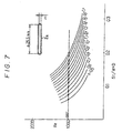
- the inventors examined the relationship between the ratio (St/W ⁇ D) of the total cross-sectional flow passage area St of the flat tubes 2a to the cross-sectional area of the core portion 2c (W ⁇ D) and the Reynold's number Re as a parameter of the inner thickness b of the flat tube 2a within a range of 0.5 - 1.7, as illustrated in Fig. 7 .
- the abscissa represents the ratio (St/W ⁇ D) and the ordinate represent the Reynold's number Re.
- the inner thickness "b" of the flat tube 2a means the thickness in the short side direction of the flow passage within the flat tube 2a in the cross-sectional shape of the flat tube 2a illustrated in FIG. 8 , and the width dimension of the long side direction is indicated with "a".
- the ratio (St/W ⁇ D) with respect to each thickness "b" of the flat tube 2a, where the Reynold's number Re is 1000, is indicated with ⁇ .
- the ratio (St/W ⁇ D) with respect to each thickness "b" of the flat tube 2a where the Reynold's number Re is 1000 or less exists in a large number.
- the inventors of the present invention also studied the optimum thickness "b" of the flat tube 2a in view of its performance, and further studied the relationship between the optimum thickness "b” and the total cross-sectional. flow passage area St of the flat tubes 2a.
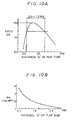
- the ordinate represents the heat radiation performance Q of the heat exchanger 2 and the abscissa represents the flow quantity Vw of the hot water circulating into the heat exchanger 2.
- the heat radiation performance Qo with the hot water flow quantity Vwo determined according to the matching point of the water flow resistance of the heat exchanger 2 and the pump characteristics of a water pump 3 of an engine 1 corresponds to the performance of the heat exchanger 2 in an actual operation.
- the heat radiability Qo of the heat exchanger 2 in an actual operation is obtained by varying the thickness "b" of the flat tube 2a and summarized in Fig. 10A .
- the optimum range of the thickness "b" of the flat tube 2a is 0.6 - 1.2 mm.
- the inner resistance of the flat tube 2a increases. Resultantly, the flow quantity of the circulating hot water decreases, and the heat radiation performance is deteriorated, as illustrated in FIG. 10A . Therefore, it is necessary to set the lower limit of the thickness "b" to 0.6 mm.
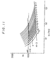
- the optimum range of the ratio of the total cross-sectional flow passage area of the flat tube 2a (St/W ⁇ D) is obtained from the optimum range of the fin height Hf (3 - 6 mm) and the optimum range of the thickness b (0.6 - 1.2 mm).
- the shaded portion X in FIG. 11 indicates the optimum range.
- total cross-sectional flow passage area ratio (St/W ⁇ D) of the flat tubes 2a By setting total cross-sectional flow passage area ratio (St/W ⁇ D) of the flat tubes 2a within the shaded portion enclosed with A, B, C and D, it is possible to control the Reynold's number Re of the flow passage of the flat tube 2a to 1000 or less within the range of hot water flow quantity for the heat exchanger 2 (maximum 16 lit/min), thereby keeping the hot water flow within the flow passage of the flat tube 2a laminar constantly.
- FIG. 13 the heat radiation performance of the heat exchanger 2 specially designed based on the above specification range is illustrated in FIG. 13 .
- the total cross-sectional flow passage area ratio (St/W ⁇ D) of the flat tube 2a is 0.145.
- the heat radiation performance Q of the heat exchanger 2 specially designed as the above was obtained.
- the heat radiation performance Q at a low flow quantity (4 lit/min when the vehicle is in idling) decreased by as small as approximately 11% down from the heat radiation performance Q at a high flow quantity (16 lit/min when the vehicle is running at 60 km/h running), which is a half or less as much as the reduction percentage (22%) in heat radiation performance of the conventional heat exchanger 2 illustrated in FIG. 2 .
- the performance is largely improved.
- FIG. 14 the relationship between the Reynold's number Re and water side heat transfer rate ⁇ w of the heat exchanger 2 based on the specifications defined in FIG. 13 is summarized.
- the heat exchanger 2 is used within a complete laminar region with the Reynold's number Re of 1000 or less, where the hot water flow quantity is 4-16 lit/min, and furthermore, the water side heat transfer rate ⁇ w within the low flow quantity region is largely improved as compared to the conventional heat exchanger.
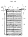
- the core portion 2c is composed of the flat tubes 2a and the corrugate fin 2b.
- Each flat tube 2a is supportably connected to core plated 2d at both ends.
- Tanks 2e and 2f are connected to the core plates 2d, respectively.
- inlet and outlet pipes 2g and 2h are detachably connected to the tanks 2e and 2f by seal joints 2i and 2j, respectively.
- an one-way flow type (full-pass type) is configured in such a manner that the hot water inlet tank 2e is disposed at an end portion of the core portion 2c over the overall width direction, the hot water outlet tank 2f is disposed at the other end portion of the core portion 2c over the overall width direction, and the hot water flows only in one direction from the inlet tank 2e to the outlet side tank 2f through the flat tube 2a.
- the heat exchanger 2 configured as the one way flow type (full-pass type) it is easily possible to decrease the cross-sectional area A per flat tube 2a and increase the total cross-sectional area St of the entire flat tubes 2a simultaneously.
- the heat exchanger 2 illustrate in FIG. 15 is made of aluminum.
- the flat tube 2a, the core plate 2d and the tanks 2e and 2f are formed from aluminum-clad material in which the aluminum core material is clad with brazing material at one or both sides.
- the corrugate fin 2b is formed from bear aluminum material which is not clad with brazing material.
- the heat exchanger 2 is integrally constructed by temporarily assembling these components, heating the assemblies within a brazing furnace to a brazing temperature, and then integrally brazing the assemblies.
- the wall thickness of the aluminum flat tube 2a is set to a range of 0.2 - 0.4 mm and the wall thickness of the aluminum corrugate fin 2b is set to a range of 0.04-0.08 mm.
- FIGS. 16A-16F illustrates modifications of the tank portion of the heat exchanger 2.
- FIGS. 16A to 16C illustrate modifications in which the width of the core portion 2c is set the same as that of the tanks 2e and 2f and the positions of the hot water inlet and outlet pipes 2g and 2h are differently modified.
- FIGS. 16D to 16F illustrate modifications in which each width of the tanks 2e and 2f is set larger than that of the core portion 2c and the hot water inlet and the positions of the outlet pipes 2g and 2h are differently modified.
- the tank 2e since the shape of the heat exchanger 2 is. symmetric with respect to the hot water flow direction of the core portion 2c, the tank 2e may be disposed on the hot water outlet side and the tank 2f may be disposed on the hot water inlet side contrary to the above embodiment.
Landscapes
- Engineering & Computer Science (AREA)
- Physics & Mathematics (AREA)
- Thermal Sciences (AREA)
- Mechanical Engineering (AREA)
- General Engineering & Computer Science (AREA)
- Geometry (AREA)
- Heat-Exchange Devices With Radiators And Conduit Assemblies (AREA)
- Air-Conditioning For Vehicles (AREA)
Description
- The present invention relates to an automotive air conditioning system according to the preamble of
claim 1. -
US 5,311,935 discloses such a heat exchanger in which hot water flows from the inlet pipe through tubes downwardly, and then passes through other tubes upwardly after being U-turned at the undermost part of the tubes. Subsequently the hot water is discharged through an outlet pipe. - The present invention is preferably applied to an automotive air conditioner in which hot water flow quantity widely varies.
- In a vehicle, as illustrated in
FIG. 1 , aconventional heat exchanger 2 for heating is installed in a cooling water (hot water) circuit of anengine 1 for running the vehicle. Hot water is circulated into theheat exchanger 2 by awater pump 3 driven by theengine 1, and the flow quantity of the hot water flowing from a flowquantity control valve 4 into theheat exchange 2 is controlled to adjust the temperature of the air flow of theheat exchanger 2. - Engine cooling water is circulated into a
radiator 6 by thewater pump 3 through athermostat 5 to cool the engine cooling water within theradiator 6. The thermostat is a well-known device, in which a valve opens when the cooling water temperature rises to or exceeds a predetermined temperature, thereby the cooling water flowing into theradiator 6. - The
reference numeral 7 denotes a bypass circuit for the engine cooling water, 8 denotes a radiator side circuit, and 9 denotes a heater side circuit. Thewater pump 3 circulates the cooling water through all thesecircuits - However, as the
water pump 3 is driven by theengine 1, a rotational speed of thewater pump 3 largely varies according to the rotational speed of theengine 1, i.e., the vehicle speed, and thereby flow quantity of the hot water into theheat exchanger 2 largely varies. - As a result of such large variation in the flow quantity of the hot water into the
exchanger 2, when the vehicle is running at a low speed (when the hot water flow quantity is small), as illustrated inFIG. 2 , there is a problem in that the heat radiation performance of theheat exchanger 2 is extremely deteriorated. - In
FIG. 2 , the ordinate represents the heat radiation performance Q of theheat exchanger 2, the abscissa represents the flow quantity Vw of the hot water into theheat exchanger 2. As can be seen fromFig. 2 , the hot water flow quantity is 16 lit/min when the vehicle is running at 60 km/h, and the hot water flow quantity is 4 lit/min when the vehicle is in idling. As the hot water flow quantity decreases, the heat radiation performance when the vehicle is in idling falls by 22 % down as compared to when the vehicle is running at 60 km/h. As a result, heating feeling is deteriorated. - Particularly when the vehicle is running in urban streets, as the vehicle is subjected to frequent starts and stops due to traffic signals. Therefore, there is a problem in that whenever the vehicle comes to be in idling, the passenger feels insufficient in heating, and heating feeling is excessively deteriorated.
- The inventors of the present invention have studied the cause of such deterioration of the heat radiation performance from various points of view and found out the following reasons.
- As illustrated in
FIG. 3 , theheat exchanger 2 includes a plurality offlat tubes 2a arranged in parallel with the air flow direction. Theseflat tubes 2a are individually disposed in a single row.Corrugate fins 2b are disposed between each pair offlat tubes 2a, thereby configuring a corrugate type heat exchanger. Thereference numeral 2c denotes a core portion which is composed of theflat tubes 2a and thecorrugate fins 2b. - In
FIG. 4 , the ordinate represents water side heat transfer rate αw of theflat tube 2a, and the abscissa represents the Reynold's number Re and hot water flow quantity Vw of the hot water passages formed with theflat tubes 2a. - As understood from
FIG. 4 , the Reynold's number is within a range of 500 - 2200 when the hot water flowing into theheat exchanger 2 is within a predetermined range (16 lit/min when the vehicle is running at 60 km/h, and 4 lit/min when the vehicle is in idling), and theheat exchanger 2 is operated to the extent from the laminar region to a transition flow region. For this reason, the water side heat transfer rate αw largely varies in accordance with the variation of the hot water flow quantity. As a result, it turned out that the water side heat transfer rate αw largely falls within the low flow quantity region, thereby causing the deterioration of the heat radiation performance when the vehicle is in idling. -
FIG. 4 illustrates the results of an experiment in which normal tubes with no dimples (concave and convex portion) for facilitating the turbulence of the hot water on the inner surfaces were used as theflat tubes 2a. - For improving the water side heat transfer rate αw, in general, the turbulence of the hot water within the tubes is often facilitated. Concretely, it has been proposed that a turbulence generator for facilitating turbulence is inserted into the tubes or dimples for facilitating turbulence is formed on the inner surfaces of the tubes.
- Therefore, the inventors of the present invention have measured the water side heat transfer rate αw by using the
flat tubes 2a with dimples for facilitating turbulence. As a result, as illustrated inFIG. 5 , the flat tube with dimples could generally improve the water side heat transfer rate αw as compared to the normal tube, and the Reynold's number Re of the dimple tube in the transition region from laminar to turbulence decreased from 1400 with the normal tube to 1000. - However, the large variation in the water side heat transfer rate αw according to the hot water flow quantity still remained even when the flat tube with dimples is used. Therefore, even when a technique for facilitating a turbulence such as the flat tubes with dimples is used, it is not possible to solve the problem in that the heat radiation performance when the hot water flow quantity is small (when the vehicle is running at a low speed) is deteriorated.
- In view of the above problems, the present invention has an object to provide an air conditioning system which can effectively improve the heat radiation performance within a low flow quantity region.
- This object is solved by the features of the charaterizing part of
claim 1. - As understood form
FIGS. 4 and5 , when the Reynold's number of approximately 1000 was taken as a transition point, the variation (inclination) of the water side heat transfer rate αw against the Reynold's number within the laminar region was very small in the region with the Reynold's number of 1000 or less. - In consideration of such small variation (inclination) of the water side heat transfer rate αw within the laminar region, in the present invention, the Reynold's number of the flow passages of the flat tubes is set to be extremely small to keep water flow in the flow passages of the flat tubes in a complete laminar region over the regular use range of the hot water flow quantity from the high flow quantity region to the low flow quantity region, thereby reducing the variation in the water side heat transfer rate αw and increasing the water side heat transfer rate αw simultaneously to improve the heat radiation performance with the low flow quantity region.
- The Reynold's number is set to 1000 or less when flow quantity of the hot water passing through the core portion is 16 lit/min.
- According to another aspect of the present invention as the above, it is possible to reduce the Reynold's number of the flow passages of the flat tubes and to keep the laminar region constantly even if the hot water flow quantity widely varies. As a result, the variation in the water side heat transfer rate can be reduced and, even in the low flow quantity region of the hot water flow quantity, it is possible to largely improve the heat radiation performance as compared to the conventional type, thereby heating feeling for the user of the heating system being remarkably improved.
- In an automotive air conditioning system, since the hot water flow quantity frequently varies due to the repetition of starts and stops of a vehicle, the improvement in the heating feeling as described above is extremely useful.
- Additional objects and advantages of the present invention will be more readily apparent from the following detailed description of preferred embodiments thereof when taken together with the accompanying drawings in which:
-
FIG. 1 is a diagram illustrating an engine cooling water circuit; -
FIG. 2 is a graph illustrating the relationship between the hot water flow quantity and heat radiation performance of a heat exchanger in a conventional automotive air conditioning system; -
FIG. 3 is a perspective view illustrating the core portion of a heat exchanger of an embodiment according to the present invention; -
FIG. 4 is a graph illustrating the relationship among the hot water flow quantity, Reynold's number and water side heat transfer rate of a heat exchanger in a conventional automotive air conditioning system; -
FIG. 5 is a graph illustrating the relationship among the hot water flow quantity, Reynold's number and water side heat transfer rate of another heat exchanger in a conventional automotive air conditioning system; -
FIG. 6 is a graph illustrating the relationship between the corrugate fin height and heat radiation performance of an the heat exchanger of the embodiment according to the present invention; -
FIG. 7 is a graph illustrating the relationship between the total cross-sectional area ratio of flat tubes and Reynold's number of the heat exchanger of the embodiment according to the present invention; -
FIG. 8 is a cross-sectional view illustrating the flat tube of the heat exchanger of the embodiment according to the present invention; -
FIG. 9 is a graph illustrating the relationship between the hot water flow quantity and heat radiation performance of the heat exchanger of the embodiment according to the present invention; -
FIG. 10A is a graph illustrating the relationship between the inner thickness of flat tube and heat radiation performance of the heat exchanger of the embodiment according to the present invention; -
FIG. 10B is a graph illustrating the relationship between the inner thickness of the flat tube and water side heat transfer rate of the heat exchanger of the embodiment according to the present invention; -
FIG. 11 is a graph illustrating the relationship among the total cross-sectional area ratio of flat tubes Reynold's number and corrugate fin height of the heat exchanger of the embodiment according to the present invention; -
FIG. 12 is a graph illustrating the relationship among the total cross-sectional area ratio of flat tubes, inner thickness of flat tube and corrugate fin height of the heat exchanger in an air conditioning system according to the present invention; -
FIG. 13 is a graph illustrating the relationship between the hot water flow quantity and heat radiation performance of the heat exchanger of the embodiment according to the present invention; -
FIG. 14 is a graph illustrating the relationship among the hot water flow quantity, Reynold's number and water side heat transfer of the heat exchanger of the embodiment according to the present invention as compared to the conventional type; -
FIG. 15 is a half cross-sectional front view illustrating an embodiment of the heat exchanger of the embodiment according to the present invention; and -
FIGS. 16A-16F are schematic front views illustrating modifications of the heat exchanger of the embodiment according to the present invention. - An embodiment of the present invention will now be described with reference to the drawings.
- In
FIG. 3 , dimensions W (width), D (thickness) and H (height) of thecore portion 2c of theheat exchanger 2 are generally set as W = 100 - 300 mm, D = 16 - 42 mm and H = 100 - 300 mm in consideration of mounting theheat exchanger 2 easily within a heater unit housing of an automotive air conditioning system and the required heat radiation performance. - As illustrated in
FIG. 6 , it is optimized that the height Hf of acorrugate fin 2b is set in a range of 3 - 6 mm with 4.5 mm in the center, in consideration of the heat radiation performance, which is described inUS 5, 311, 935. - To keep the flow passages within
flat tubes 2a as a laminar region constantly by setting the Reynold's number Re to a small value, the flow velocity v of hot water within theflat tubes 2a and the equivalent diameter de of theflat tube 2a should be reduced by using the following equation (1).
flat tubes 2a, and the substantial round-hole diameter de of theflat tube 2a is the diameter of the round-hole having the same area as the cross-sectional area of theflat tube 2a. - To reduce the flow velocity v of the hot water within the
flat tubes 2a, the total area St of the flow passages of theflat tubes 2a should be increased by using the following equation (2).
heat exchanger 2 and St is the sum total of the cross-sectional areas of the flow passages within all theflat tubes 2a of thecore portion 2c. - To reduce the substantial diameter de of the
flat tube 2a, the cross-sectional area A of the flow passage perflat tube 2a should be reduced by using thefollowing equation 3.
flat tube 2a (the length of the inner peripheral wall of the cross-sectional shape of theflat tube 2a, which will be described later with reference toFIGS. 7 and8 ). - A liquid mixture of an antifreeze solution containing a rust preventive and water combined at approximately 50:50 is generally used for the hot water (engine cooling water) circulating into the
heat exchanger 2, and the hot water temperature is maintained to approximately 85° C by thethermostat 5. - Here, to reduce the cross-sectional flow passage area A per
flat tube 2a and to increase the total cross-sectional flow passage area St of theflat tubes 2a are contrary to each other. Therefore, to increase the total cross-sectional tube area St while reducing the cross-sectional flow passage area A perflat tube 2a, it is preferable that thecore portion 2c of the following construction being employed. - The
core portion 2c should be an one way flow type (full-pass type) having the cross-sectional area (W×D) of thecore portion 2c in which the hot water flows only in one direction instead of U-turn type in which the hot water flows in a U-turn, and the number of theflat tubes 2a having the cross-sectional area (W×D) of thecore portion 2c, through which the hot water flows in parallel, should be increased. The concrete structure of thecore portion 2c of the one way flow type (full-pass type) will be described later with reference toFIG. 15 . - Next, for the
core portion 2c dimensioned to W (width) = 180 mm, H (height) = 180 mm and D (thickness) = 27 mm, the inventor of the present invention examined the total cross-sectional flow passage area St of theflat tubes 2a which could hold the Reynold's number Re to be 1000 or less (within the complete laminar region inFIG. 5 ) until the hot water flow quantity Vw increases to 16 lit/min, which is a flow quantity when the vehicle is running at a speed of 60 km/h. - Since the total cross-sectional flow passage area St of the
flat tubes 2a varies according to the size (W, D) of thecore portion 2c, the inventors examined the relationship between the ratio (St/W×D) of the total cross-sectional flow passage area St of theflat tubes 2a to the cross-sectional area of thecore portion 2c (W×D) and the Reynold's number Re as a parameter of the inner thickness b of theflat tube 2a within a range of 0.5 - 1.7, as illustrated inFig. 7 . InFig. 7 , the abscissa represents the ratio (St/W×D) and the ordinate represent the Reynold's number Re. - The inner thickness "b" of the
flat tube 2a means the thickness in the short side direction of the flow passage within theflat tube 2a in the cross-sectional shape of theflat tube 2a illustrated inFIG. 8 , and the width dimension of the long side direction is indicated with "a". - In the experiment which result is illustrated in
FIG. 7 , the inner width "a" of theflat tube 2a was fixed to 26.5 mm and the inner thickness "b" was changed. - The ratio (St/W×D) with respect to each thickness "b" of the
flat tube 2a, where the Reynold's number Re is 1000, is indicated with ○. As illustrated inFIG. 7 , the ratio (St/W×D) with respect to each thickness "b" of theflat tube 2a where the Reynold's number Re is 1000 or less exists in a large number. - Therefore, the inventors of the present invention also studied the optimum thickness "b" of the
flat tube 2a in view of its performance, and further studied the relationship between the optimum thickness "b" and the total cross-sectional. flow passage area St of theflat tubes 2a. - Specifically, the inventors studied on the
core portion 2c with the width W = 180 mm, the height H = 180 mm and the thickness D = 27 mm, and the fin height Hf being the central value 4.5 mm of the optimum range (3 - 6 mm) to optimize the thickness "b" of theflat tube 2a in view of its performance. - In
FIG. 9 , the ordinate represents the heat radiation performance Q of theheat exchanger 2 and the abscissa represents the flow quantity Vw of the hot water circulating into theheat exchanger 2. The heat radiation performance Qo with the hot water flow quantity Vwo determined according to the matching point of the water flow resistance of theheat exchanger 2 and the pump characteristics of awater pump 3 of anengine 1 corresponds to the performance of theheat exchanger 2 in an actual operation. - The heat radiability Qo of the
heat exchanger 2 in an actual operation is obtained by varying the thickness "b" of theflat tube 2a and summarized inFig. 10A . InFig. 10A , the heat radiation performance Qo of the thickness b = 0.7 mm at which the heat radiation performance Qo of theheat exchanger 2 in an actual operation is the highest is set to 100, the ordinate represents the percentage of the heat radiation performance Qo of each thickness "b" of theflat tube 2a against the heat radiation performance Qo = 100 of such thickness b = 0.7 mm of theflat tube 2a. - It is understood from
FIG. 10A that the optimum range of the thickness "b" of theflat tube 2a is 0.6 - 1.2 mm. -
FIG. 10B illustrates the relationship between the thickness b of theflat tube 2a and water side heat transfer rate αw with the Reynold's number Re = 500. The smaller the dimension "b" is, the higher the water side heat transfer rate αw is. As a matter of fact, however, when the dimension "b" decreases, the inner resistance of theflat tube 2a increases. Resultantly, the flow quantity of the circulating hot water decreases, and the heat radiation performance is deteriorated, as illustrated inFIG. 10A . Therefore, it is necessary to set the lower limit of the thickness "b" to 0.6 mm. - Based on the above results, the optimum range of the ratio of the total cross-sectional flow passage area of the
flat tube 2a (St/W×D) is obtained from the optimum range of the fin height Hf (3 - 6 mm) and the optimum range of the thickness b (0.6 - 1.2 mm). The shaded portion X inFIG. 11 indicates the optimum range. - As illustrated in
FIG. 12 , when this optimum range is rewritten by taking the total cross-sectional flow passage area ratio (St/W×D) of theflat tubes 2a as the ordinate and the thickness "b" of theflat tube 2a as the abscissa, in a combination of the optimum fin height (Hf = 3 - 6 mm) and the optimum tube thickness (b = 0.6 - 1.2 mm), the total cross-sectional flow passage area ratio (St/W×D) of theflat tubes 2a is identical to the shaded portion enclosed with A, B, C and D inFIG. 12 , i.e., the range of 0.07 - 0.24. - By setting total cross-sectional flow passage area ratio (St/W×D) of the
flat tubes 2a within the shaded portion enclosed with A, B, C and D, it is possible to control the Reynold's number Re of the flow passage of theflat tube 2a to 1000 or less within the range of hot water flow quantity for the heat exchanger 2 (maximum 16 lit/min), thereby keeping the hot water flow within the flow passage of theflat tube 2a laminar constantly. - Now, the heat radiation performance of the
heat exchanger 2 specially designed based on the above specification range is illustrated inFIG. 13 . Theheat exchanger 2 illustrated inFIG. 13 is dimensioned to the width W = 180 mm, height H = 180 mm and thickness D = 27 mm in thecore portion 2c, the height Hf = 4.5 mm in thecorrugate fin 2b, and the thickness b = 0.9 mm in theflat tube 2a, which are the central values of the optimum range, respectively. - The total cross-sectional flow passage area ratio (St/W×D) of the
flat tube 2a is 0.145. The heat radiation performance Q of theheat exchanger 2 specially designed as the above was obtained. As a result, as illustrated inFIG. 13 , the heat radiation performance Q at a low flow quantity (4 lit/min when the vehicle is in idling) decreased by as small as approximately 11% down from the heat radiation performance Q at a high flow quantity (16 lit/min when the vehicle is running at 60 km/h running), which is a half or less as much as the reduction percentage (22%) in heat radiation performance of theconventional heat exchanger 2 illustrated inFIG. 2 . As clearly understood, the performance is largely improved. - In
FIG. 14 , the relationship between the Reynold's number Re and water side heat transfer rate αw of theheat exchanger 2 based on the specifications defined inFIG. 13 is summarized. As understood fromFIG. 14 , theheat exchanger 2 is used within a complete laminar region with the Reynold's number Re of 1000 or less, where the hot water flow quantity is 4-16 lit/min, and furthermore, the water side heat transfer rate αw within the low flow quantity region is largely improved as compared to the conventional heat exchanger. - Next, an embodiment where the
heat exchanger 2 designed based on the above specifications is applied to the automotive air conditioning system is described with reference toFig. 15 . Thecore portion 2c is composed of theflat tubes 2a and thecorrugate fin 2b. Eachflat tube 2a is supportably connected to core plated 2d at both ends.Tanks core plates 2d, respectively. Further, inlet andoutlet pipes 2g and 2h are detachably connected to thetanks seal joints 2i and 2j, respectively. - In
FIG. 15 , for example, when the pipe 2g is connected to the hot water inlet side of the hot water circuit of theengine 1, the hot water from the hot water inlet pipe 2g flows through the hotwater inlet tank 2e, theflat tubes 2a, the hotwater outlet tank 2f and the hotwater outlet pipe 2h in this order. - That is, an one-way flow type (full-pass type) is configured in such a manner that the hot
water inlet tank 2e is disposed at an end portion of thecore portion 2c over the overall width direction, the hotwater outlet tank 2f is disposed at the other end portion of thecore portion 2c over the overall width direction, and the hot water flows only in one direction from theinlet tank 2e to theoutlet side tank 2f through theflat tube 2a. - In the
heat exchanger 2 configured as the one way flow type (full-pass type), it is easily possible to decrease the cross-sectional area A perflat tube 2a and increase the total cross-sectional area St of the entireflat tubes 2a simultaneously. - The
heat exchanger 2 illustrate inFIG. 15 is made of aluminum. Theflat tube 2a, thecore plate 2d and thetanks corrugate fin 2b is formed from bear aluminum material which is not clad with brazing material. Theheat exchanger 2 is integrally constructed by temporarily assembling these components, heating the assemblies within a brazing furnace to a brazing temperature, and then integrally brazing the assemblies. - Here, in view of heat transfer rate, strength, etc., the wall thickness of the aluminum
flat tube 2a is set to a range of 0.2 - 0.4 mm and the wall thickness of thealuminum corrugate fin 2b is set to a range of 0.04-0.08 mm. -
FIGS. 16A-16F illustrates modifications of the tank portion of theheat exchanger 2.FIGS. 16A to 16C illustrate modifications in which the width of thecore portion 2c is set the same as that of thetanks outlet pipes 2g and 2h are differently modified. -
FIGS. 16D to 16F illustrate modifications in which each width of thetanks core portion 2c and the hot water inlet and the positions of theoutlet pipes 2g and 2h are differently modified. - In
FIGS. 15 and16 , since the shape of theheat exchanger 2 is. symmetric with respect to the hot water flow direction of thecore portion 2c, thetank 2e may be disposed on the hot water outlet side and thetank 2f may be disposed on the hot water inlet side contrary to the above embodiment.
Claims (5)
- An automobile air conditioning system comprising a corrugate fin type heat exchanger (2) for heat exchanging hot water with air, which is used for a heater core of an automotive air conditioner, said corrugate fin type heat exchanger (2) comprising:a) a plurality of flat tubes (2a) disposed in parallel with a flow direction of said air, the flat tubes (2a) are disposed in a single line in said flow direction;b) at least one corrugate fin (2b) disposed between each pair of said flat tubes (2a) and connected thereto;c) the height of said corrugate fin (2b) is in a range of 3 - 6 mm;d) said flat tubes (2a) and said corrugate fins (2b) are made of aluminum,e) said plurality of flat tubes (2a) and said corrugate fin (2b) composing a core portion (2c),f) a hot water inlet tank (2e) disposed at an end of said core portion (2c), said hot water inlet tank (2e) communicating with said plurality of flat tubes (2a) for introducing said hot water into said flat tube (2a); andg) a hot water outlet tank (2f) disposed at an end of said core portion (2c), said hot water outlet tank (2f) communicating with said plurality of flat tubes (2a) for receiving said hot water flowing from said flat tubes (2a),
characterised in thath) said core portion (2c) is constructed in such a manner that said hot water flows only in one direction from said hot water inlet tank (2e) at one end of the said core portion (2c) to said hot water outlet tank (2f) at the other end of said core portion (2c),i) a ratio (St/W X D) of the total cross-sectional flow passage area (St) of said plurality of flat tubes (2a) to the cross-sectional area (W X D) expressed by an overall width dimension (W) and a thickness dimension (D) of said core portion (2c) is set to a range of 0.07 - 0.24 according to said inner thickness of said flat tube (2a) and said height of said corrugate fin (2b);j) the inner thickness in the short side direction of the flow passage within the flat tube (2a) is in a range of 0.6 - 1.2 mm;k) a wall thickness of said flat tube (2a) is set to a range of 0.2 - 0.4 mm; andl) a wall thickness of said corrugate fin (2b) is set to a range of 0.04 - 0.08 mm,m) wherein said hot water is circulated by a water pump (3) driven by an automotive engine, and the Reynolds number is set to 1000 or less when the flow quantity of said hot water passing through said core portion (2c) is 16 lit/min when the vehicle is running at 60 km/h. - An automobile air conditioning system according to claim 1, further comprising:an inlet pipe (2g) connected to said hot water inlet tank (2e) to introduce said hot water into said inlet tank (2e);an outlet pipe (2h) connected to said hot water outlet tank (2f) to lead said hot water out of said outlet tank (2f).
- An automobile air conditioning system according to claim 2, wherein said inlet pipe (2g) an said outlet pipe (2h) extend in a longitudinal direction of said hot water inlet tank (2e) and said hot water outlet tank (2f), respectively.
- An automobile air conditioning system according to claim 2, wherein said inlet pipe (2g) and said outlet pipe (2h) extend in a lateral direction of said hot water inlet tank (2e) and said hot water outlet tank (2f), respectively.
- An automobile air conditioning system according to claim 1, comprising the corrugate fin type heat exchanger (2), wherein said hot water is circulated by a water pump (3) driven by an automotive engine and passes through a radiator (6) for cooling said hot water by heat exchanging with air and being disposed in a cooling water pipe (8) communicating between said engine and said radiator (6), and said heat exchanger (2) being disposed in a hot water pipe (9) arranged in parallel with said cooling water pipe (8).
Applications Claiming Priority (3)
| Application Number | Priority Date | Filing Date | Title |
|---|---|---|---|
| JP270833/94 | 1994-11-04 | ||
| JP27083394 | 1994-11-04 | ||
| JP27083394A JP3355824B2 (en) | 1994-11-04 | 1994-11-04 | Corrugated fin heat exchanger |
Publications (4)
| Publication Number | Publication Date |
|---|---|
| EP0710811A2 EP0710811A2 (en) | 1996-05-08 |
| EP0710811A3 EP0710811A3 (en) | 1997-10-29 |
| EP0710811B1 EP0710811B1 (en) | 2003-10-15 |
| EP0710811B2 true EP0710811B2 (en) | 2010-08-11 |
Family
ID=17491654
Family Applications (1)
| Application Number | Title | Priority Date | Filing Date |
|---|---|---|---|
| EP95117346A Expired - Lifetime EP0710811B2 (en) | 1994-11-04 | 1995-11-03 | An automobile air conditioning system |
Country Status (7)
| Country | Link |
|---|---|
| US (1) | US5564497A (en) |
| EP (1) | EP0710811B2 (en) |
| JP (1) | JP3355824B2 (en) |
| KR (1) | KR100249468B1 (en) |
| CN (1) | CN1092325C (en) |
| AU (1) | AU688601B2 (en) |
| DE (1) | DE69531922T3 (en) |
Families Citing this family (71)
| Publication number | Priority date | Publication date | Assignee | Title |
|---|---|---|---|---|
| JP3578291B2 (en) * | 1995-09-08 | 2004-10-20 | 日本軽金属株式会社 | Method and apparatus for applying brazing composition |
| US5854739A (en) * | 1996-02-20 | 1998-12-29 | International Electronic Research Corp. | Long fin omni-directional heat sink |
| US5979544A (en) * | 1996-10-03 | 1999-11-09 | Zexel Corporation | Laminated heat exchanger |
| DE69733284T2 (en) | 1996-12-25 | 2005-10-06 | Calsonic Kansei Corp. | Capacitor body structure |
| DE19719252C2 (en) * | 1997-05-07 | 2002-10-31 | Valeo Klimatech Gmbh & Co Kg | Double-flow and single-row brazed flat tube evaporator for a motor vehicle air conditioning system |
| DE19758886B4 (en) * | 1997-05-07 | 2017-09-21 | Valeo Klimatechnik Gmbh & Co. Kg | Two-flow and single-tube brazed flat tube evaporator in the air direction for an automotive air conditioning system |
| FR2764647B1 (en) * | 1997-06-17 | 2001-12-14 | Valeo Thermique Moteur Sa | ECONOMICAL CONSTRUCTION BOOST AIR COOLER |
| US6339937B1 (en) * | 1999-06-04 | 2002-01-22 | Denso Corporation | Refrigerant evaporator |
| JP2001021287A (en) * | 1999-07-08 | 2001-01-26 | Zexel Valeo Climate Control Corp | Heat exchanger |
| JP2001165532A (en) * | 1999-12-09 | 2001-06-22 | Denso Corp | Refrigerant condenser |
| US6749007B2 (en) * | 2000-08-25 | 2004-06-15 | Modine Manufacturing Company | Compact cooling system with similar flow paths for multiple heat exchangers |
| US20030131976A1 (en) * | 2002-01-11 | 2003-07-17 | Krause Paul E. | Gravity fed heat exchanger |
| DE10212249A1 (en) * | 2002-03-20 | 2003-10-02 | Behr Gmbh & Co | Heat exchanger and cooling system |
| EP1359383A2 (en) | 2002-05-03 | 2003-11-05 | Behr GmbH & Co. | Heat exchanger |
| US6688380B2 (en) | 2002-06-28 | 2004-02-10 | Aavid Thermally, Llc | Corrugated fin heat exchanger and method of manufacture |
| JP2006522463A (en) | 2002-11-01 | 2006-09-28 | クーリギー インコーポレイテッド | Optimal spreader system, apparatus and method for micro heat exchange cooled by fluid |
| US7836597B2 (en) | 2002-11-01 | 2010-11-23 | Cooligy Inc. | Method of fabricating high surface to volume ratio structures and their integration in microheat exchangers for liquid cooling system |
| US20050211418A1 (en) * | 2002-11-01 | 2005-09-29 | Cooligy, Inc. | Method and apparatus for efficient vertical fluid delivery for cooling a heat producing device |
| US7156159B2 (en) * | 2003-03-17 | 2007-01-02 | Cooligy, Inc. | Multi-level microchannel heat exchangers |
| US20040112571A1 (en) * | 2002-11-01 | 2004-06-17 | Cooligy, Inc. | Method and apparatus for efficient vertical fluid delivery for cooling a heat producing device |
| FR2847974B1 (en) * | 2002-12-03 | 2006-02-10 | Valeo Climatisation | HEAT EXCHANGER TUBES HAVING ASSOCIATED DISTURBERS AND EXCHANGERS. |
| US7201012B2 (en) * | 2003-01-31 | 2007-04-10 | Cooligy, Inc. | Remedies to prevent cracking in a liquid system |
| US7293423B2 (en) | 2004-06-04 | 2007-11-13 | Cooligy Inc. | Method and apparatus for controlling freezing nucleation and propagation |
| US7044196B2 (en) * | 2003-01-31 | 2006-05-16 | Cooligy,Inc | Decoupled spring-loaded mounting apparatus and method of manufacturing thereof |
| US20040233639A1 (en) * | 2003-01-31 | 2004-11-25 | Cooligy, Inc. | Removeable heat spreader support mechanism and method of manufacturing thereof |
| US6904963B2 (en) * | 2003-06-25 | 2005-06-14 | Valeo, Inc. | Heat exchanger |
| US7591302B1 (en) | 2003-07-23 | 2009-09-22 | Cooligy Inc. | Pump and fan control concepts in a cooling system |
| US20050045314A1 (en) * | 2004-08-26 | 2005-03-03 | Valeo, Inc. | Aluminum heat exchanger and method of making thereof |
| US6912864B2 (en) | 2003-10-10 | 2005-07-05 | Hussmann Corporation | Evaporator for refrigerated merchandisers |
| JP2005122503A (en) | 2003-10-17 | 2005-05-12 | Hitachi Ltd | Cooling apparatus and electronic equipment incorporating the same |
| EP1548380A3 (en) * | 2003-12-22 | 2006-10-04 | Hussmann Corporation | Flat-tube evaporator with micro-distributor |
| US20050189096A1 (en) * | 2004-02-26 | 2005-09-01 | Wilson Michael J. | Compact radiator for an electronic device |
| US8101431B2 (en) | 2004-02-27 | 2012-01-24 | Board Of Regents, The University Of Texas System | Integration of fluids and reagents into self-contained cartridges containing sensor elements and reagent delivery systems |
| US7188662B2 (en) * | 2004-06-04 | 2007-03-13 | Cooligy, Inc. | Apparatus and method of efficient fluid delivery for cooling a heat producing device |
| US20050269691A1 (en) * | 2004-06-04 | 2005-12-08 | Cooligy, Inc. | Counter flow micro heat exchanger for optimal performance |
| US20070184320A1 (en) * | 2004-06-24 | 2007-08-09 | Jean-Paul Domen | Cooling devices for various applications |
| CN100573017C (en) * | 2004-10-07 | 2009-12-23 | 贝洱两合公司 | Air-cooled exhaust gas heat exchanger, particularly exhaust gas cooler for motor vehicles |
| EP1800078B1 (en) * | 2004-10-07 | 2018-05-30 | MAHLE Behr GmbH & Co. KG | Air-cooled exhaust gas heat exchanger, in particular exhaust gas cooler for motor vehicles |
| US7341334B2 (en) * | 2004-10-25 | 2008-03-11 | Pitney Bowes Inc. | System and method for preventing security ink tampering |
| DE102004056592A1 (en) * | 2004-11-23 | 2006-05-24 | Behr Gmbh & Co. Kg | Low-temperature coolant radiator |
| DE102004056557A1 (en) * | 2004-11-23 | 2006-05-24 | Behr Gmbh & Co. Kg | Dimensionally optimized heat exchange device and method for optimizing the dimensions of heat exchange devices |
| JP2006207948A (en) | 2005-01-28 | 2006-08-10 | Calsonic Kansei Corp | Air-cooled oil cooler |
| WO2006101565A1 (en) * | 2005-03-18 | 2006-09-28 | Carrier Commercial Refrigeration, Inc. | Heat exchanger arrangement |
| US8377398B2 (en) | 2005-05-31 | 2013-02-19 | The Board Of Regents Of The University Of Texas System | Methods and compositions related to determination and use of white blood cell counts |
| JP2007093023A (en) * | 2005-09-27 | 2007-04-12 | Showa Denko Kk | Heat exchanger |
| JP2007093024A (en) * | 2005-09-27 | 2007-04-12 | Showa Denko Kk | Heat exchanger |
| JP2007178015A (en) * | 2005-12-27 | 2007-07-12 | Showa Denko Kk | Heat exchanger |
| US7913719B2 (en) | 2006-01-30 | 2011-03-29 | Cooligy Inc. | Tape-wrapped multilayer tubing and methods for making the same |
| TW200810676A (en) | 2006-03-30 | 2008-02-16 | Cooligy Inc | Multi device cooling |
| US7715194B2 (en) | 2006-04-11 | 2010-05-11 | Cooligy Inc. | Methodology of cooling multiple heat sources in a personal computer through the use of multiple fluid-based heat exchanging loops coupled via modular bus-type heat exchangers |
| JP5148079B2 (en) * | 2006-07-25 | 2013-02-20 | 富士通株式会社 | Heat exchanger for liquid cooling unit, liquid cooling unit and electronic equipment |
| US20080041559A1 (en) * | 2006-08-16 | 2008-02-21 | Halla Climate Control Corp. | Heat exchanger for vehicle |
| KR101208922B1 (en) * | 2006-09-21 | 2012-12-06 | 한라공조주식회사 | A Heat Exchanger |
| US20080142190A1 (en) * | 2006-12-18 | 2008-06-19 | Halla Climate Control Corp. | Heat exchanger for a vehicle |
| US20090038562A1 (en) * | 2006-12-18 | 2009-02-12 | Halla Climate Control Corp. | Cooling system for a vehicle |
| EP2140219B1 (en) | 2007-04-12 | 2023-07-12 | AutomotiveThermoTech GmbH | Motor vehicle |
| TW200912621A (en) | 2007-08-07 | 2009-03-16 | Cooligy Inc | Method and apparatus for providing a supplemental cooling to server racks |
| KR101260765B1 (en) | 2007-09-03 | 2013-05-06 | 한라비스테온공조 주식회사 | evaporator |
| US9297571B1 (en) | 2008-03-10 | 2016-03-29 | Liebert Corporation | Device and methodology for the removal of heat from an equipment rack by means of heat exchangers mounted to a door |
| US8250877B2 (en) | 2008-03-10 | 2012-08-28 | Cooligy Inc. | Device and methodology for the removal of heat from an equipment rack by means of heat exchangers mounted to a door |
| US8286693B2 (en) * | 2008-04-17 | 2012-10-16 | Aavid Thermalloy, Llc | Heat sink base plate with heat pipe |
| CN102171897A (en) | 2008-08-05 | 2011-08-31 | 固利吉股份有限公司 | A microheat exchanger for laser diode cooling |
| DE102009007619A1 (en) | 2009-02-05 | 2010-08-12 | Behr Gmbh & Co. Kg | Heat exchangers, in particular radiators for motor vehicles |
| JP5655676B2 (en) * | 2010-08-03 | 2015-01-21 | 株式会社デンソー | Condenser |
| JP5626198B2 (en) * | 2010-12-28 | 2014-11-19 | 株式会社デンソー | Refrigerant radiator |
| CN102297547B (en) * | 2011-06-27 | 2013-04-10 | 三花控股集团有限公司 | Heat exchanger |
| FR2986472B1 (en) | 2012-02-03 | 2014-08-29 | Valeo Systemes Thermiques | COOLING RADIATOR FOR A VEHICLE, IN PARTICULAR A MOTOR VEHICLE |
| CN102889812A (en) * | 2012-09-20 | 2013-01-23 | 华电重工股份有限公司 | Novel single-row tube bank for cooling air |
| KR101989096B1 (en) * | 2013-06-18 | 2019-06-13 | 엘지전자 주식회사 | Heat exchanger |
| US20140124183A1 (en) * | 2012-11-05 | 2014-05-08 | Soonchul HWANG | Heat exchanger for an air conditioner and an air conditioner having the same |
| US20140284037A1 (en) * | 2013-03-20 | 2014-09-25 | Caterpillar Inc. | Aluminum Tube-and-Fin Assembly Geometry |
Citations (5)
| Publication number | Priority date | Publication date | Assignee | Title |
|---|---|---|---|---|
| US4332293A (en) † | 1980-04-30 | 1982-06-01 | Nippondenso Co., Ltd. | Corrugated fin type heat exchanger |
| JPS62107275U (en) † | 1985-12-20 | 1987-07-09 | ||
| US4693307A (en) † | 1985-09-16 | 1987-09-15 | General Motors Corporation | Tube and fin heat exchanger with hybrid heat transfer fin arrangement |
| US4825941A (en) † | 1986-07-29 | 1989-05-02 | Showa Aluminum Kabushiki Kaisha | Condenser for use in a car cooling system |
| EP0379701B1 (en) † | 1989-01-12 | 1992-09-16 | Behr GmbH & Co. | Heat exchanger |
Family Cites Families (7)
| Publication number | Priority date | Publication date | Assignee | Title |
|---|---|---|---|---|
| US3113615A (en) * | 1961-05-08 | 1963-12-10 | Modine Mfg Co | Heat exchanger header construction |
| JPS5855695A (en) * | 1981-09-30 | 1983-04-02 | Nissan Motor Co Ltd | Heater core |
| US4998580A (en) * | 1985-10-02 | 1991-03-12 | Modine Manufacturing Company | Condenser with small hydraulic diameter flow path |
| JPH02287094A (en) * | 1989-04-26 | 1990-11-27 | Zexel Corp | Heat exchanger |
| JP3459271B2 (en) * | 1992-01-17 | 2003-10-20 | 株式会社デンソー | Heater core of automotive air conditioner |
| US5186249A (en) * | 1992-06-08 | 1993-02-16 | General Motors Corporation | Heater core |
| US5329988A (en) * | 1993-05-28 | 1994-07-19 | The Allen Group, Inc. | Heat exchanger |
-
1994
- 1994-11-04 JP JP27083394A patent/JP3355824B2/en not_active Expired - Fee Related
-
1995
- 1995-11-03 EP EP95117346A patent/EP0710811B2/en not_active Expired - Lifetime
- 1995-11-03 DE DE69531922T patent/DE69531922T3/en not_active Expired - Lifetime
- 1995-11-03 KR KR1019950039595A patent/KR100249468B1/en not_active IP Right Cessation
- 1995-11-03 CN CN95118321A patent/CN1092325C/en not_active Expired - Fee Related
- 1995-11-03 US US08/552,979 patent/US5564497A/en not_active Expired - Lifetime
- 1995-11-06 AU AU36673/95A patent/AU688601B2/en not_active Ceased
Patent Citations (6)
| Publication number | Priority date | Publication date | Assignee | Title |
|---|---|---|---|---|
| US4332293A (en) † | 1980-04-30 | 1982-06-01 | Nippondenso Co., Ltd. | Corrugated fin type heat exchanger |
| US4693307A (en) † | 1985-09-16 | 1987-09-15 | General Motors Corporation | Tube and fin heat exchanger with hybrid heat transfer fin arrangement |
| JPS62107275U (en) † | 1985-12-20 | 1987-07-09 | ||
| US4825941A (en) † | 1986-07-29 | 1989-05-02 | Showa Aluminum Kabushiki Kaisha | Condenser for use in a car cooling system |
| US4825941B1 (en) † | 1986-07-29 | 1997-07-01 | Showa Aluminum Corp | Condenser for use in a car cooling system |
| EP0379701B1 (en) † | 1989-01-12 | 1992-09-16 | Behr GmbH & Co. | Heat exchanger |
Non-Patent Citations (3)
| Title |
|---|
| Lehrbuch der Klimatechnik, Verlag C. F. Müller Karlsruhe 1997 † |
| Noboro Ogasawara, Ichiro Iwai, Tsuyoshi kawabe, Toru Karaki, "A Developemt of a Light Weight and High performance Aluminium Radiator", SAE Technical Paper Series, Nr. 920549, February 1992. † |
| Test results: "Effet de l'épaisseur intercalaire sur la performance en faisant varier la hauteur intercalaire" † |
Also Published As
| Publication number | Publication date |
|---|---|
| KR960018502A (en) | 1996-06-17 |
| AU688601B2 (en) | 1998-03-12 |
| DE69531922T3 (en) | 2010-12-09 |
| AU3667395A (en) | 1996-05-09 |
| CN1128344A (en) | 1996-08-07 |
| KR100249468B1 (en) | 2000-04-01 |
| DE69531922T2 (en) | 2004-07-29 |
| EP0710811A2 (en) | 1996-05-08 |
| JP3355824B2 (en) | 2002-12-09 |
| US5564497A (en) | 1996-10-15 |
| EP0710811A3 (en) | 1997-10-29 |
| JPH08136176A (en) | 1996-05-31 |
| EP0710811B1 (en) | 2003-10-15 |
| DE69531922D1 (en) | 2003-11-20 |
| CN1092325C (en) | 2002-10-09 |
Similar Documents
| Publication | Publication Date | Title |
|---|---|---|
| EP0710811B2 (en) | An automobile air conditioning system | |
| US5311935A (en) | Corrugated fin type heat exchanger | |
| US4332293A (en) | Corrugated fin type heat exchanger | |
| US6341648B1 (en) | Heat exchanger having heat-exchanging core portion divided into plural core portions | |
| EP1239129B1 (en) | Cooling system for water-cooled internal combustion engine and control method applicable to cooling system therefor | |
| EP1348846A2 (en) | Water-cooled type engine cooling apparatus and transmission oil cooler module | |
| EP1106951A2 (en) | Continuous combination fin for a heat exchanger | |
| EP1998133A1 (en) | Heat exchanger and integrated-type heat exchanger | |
| US9115934B2 (en) | Heat exchanger flow limiting baffle | |
| EP1195568B1 (en) | Heat exchanger having several heat exchanging portions | |
| CN1082177C (en) | Heat exchanger of air conditioner | |
| US20110192584A1 (en) | Heat exchanger | |
| GB1571048A (en) | Heat exchanger | |
| US5975200A (en) | Plate-fin type heat exchanger | |
| US7174953B2 (en) | Stacking-type, multi-flow, heat exchanger | |
| EP0857935A2 (en) | Integral type heat exchanger | |
| EP0632246A2 (en) | Heat exchanger | |
| JP3627295B2 (en) | Heat exchanger | |
| EP0803695B1 (en) | Plate-fin heat exchanger | |
| JP3607007B2 (en) | Air conditioner | |
| CN114322105B (en) | Heat exchanger and air conditioning system | |
| JPS63163785A (en) | Heat exchanger | |
| EP0816146A2 (en) | Heat exchanger and methods for making heat exchangers | |
| JPH04172172A (en) | Manufacture of heat exchanger | |
| JP2021167179A (en) | On-vehicle heat exchanger |
Legal Events
| Date | Code | Title | Description |
|---|---|---|---|
| PUAI | Public reference made under article 153(3) epc to a published international application that has entered the european phase |
Free format text: ORIGINAL CODE: 0009012 |
|
| AK | Designated contracting states |
Kind code of ref document: A2 Designated state(s): DE FR GB IT |
|
| RAP1 | Party data changed (applicant data changed or rights of an application transferred) |
Owner name: DENSO CORPORATION |
|
| PUAL | Search report despatched |
Free format text: ORIGINAL CODE: 0009013 |
|
| AK | Designated contracting states |
Kind code of ref document: A3 Designated state(s): DE FR GB IT |
|
| 17P | Request for examination filed |
Effective date: 19971125 |
|
| 17Q | First examination report despatched |
Effective date: 20000425 |
|
| GRAH | Despatch of communication of intention to grant a patent |
Free format text: ORIGINAL CODE: EPIDOS IGRA |
|
| GRAH | Despatch of communication of intention to grant a patent |
Free format text: ORIGINAL CODE: EPIDOS IGRA |
|
| GRAS | Grant fee paid |
Free format text: ORIGINAL CODE: EPIDOSNIGR3 |
|
| GRAA | (expected) grant |
Free format text: ORIGINAL CODE: 0009210 |
|
| AK | Designated contracting states |
Kind code of ref document: B1 Designated state(s): DE FR GB IT |
|
| REG | Reference to a national code |
Ref country code: GB Ref legal event code: FG4D |
|
| REF | Corresponds to: |
Ref document number: 69531922 Country of ref document: DE Date of ref document: 20031120 Kind code of ref document: P |
|
| ET | Fr: translation filed | ||
| PLBQ | Unpublished change to opponent data |
Free format text: ORIGINAL CODE: EPIDOS OPPO |
|
| PLBI | Opposition filed |
Free format text: ORIGINAL CODE: 0009260 |
|
| PLAX | Notice of opposition and request to file observation + time limit sent |
Free format text: ORIGINAL CODE: EPIDOSNOBS2 |
|
| 26 | Opposition filed |
Opponent name: BEHR GMBH & CO. KG Effective date: 20040715 Opponent name: VALEO THERMIQUE MOTEUR Effective date: 20040715 Opponent name: MODINE EUROPE GMBH Effective date: 20040714 |
|
| PLAX | Notice of opposition and request to file observation + time limit sent |
Free format text: ORIGINAL CODE: EPIDOSNOBS2 |
|
| PLBB | Reply of patent proprietor to notice(s) of opposition received |
Free format text: ORIGINAL CODE: EPIDOSNOBS3 |
|
| PLAY | Examination report in opposition despatched + time limit |
Free format text: ORIGINAL CODE: EPIDOSNORE2 |
|
| PLBC | Reply to examination report in opposition received |
Free format text: ORIGINAL CODE: EPIDOSNORE3 |
|
| PLAH | Information related to despatch of examination report in opposition + time limit modified |
Free format text: ORIGINAL CODE: EPIDOSCORE2 |
|
| PLAT | Information related to reply to examination report in opposition deleted |
Free format text: ORIGINAL CODE: EPIDOSDORE3 |
|
| PLBC | Reply to examination report in opposition received |
Free format text: ORIGINAL CODE: EPIDOSNORE3 |
|
| PLAP | Information related to despatch of examination report in opposition + time limit deleted |
Free format text: ORIGINAL CODE: EPIDOSDORE2 |
|
| PLAT | Information related to reply to examination report in opposition deleted |
Free format text: ORIGINAL CODE: EPIDOSDORE3 |
|
| PLAY | Examination report in opposition despatched + time limit |
Free format text: ORIGINAL CODE: EPIDOSNORE2 |
|
| PLBC | Reply to examination report in opposition received |
Free format text: ORIGINAL CODE: EPIDOSNORE3 |
|
| PLAL | Information related to reply to examination report in opposition modified |
Free format text: ORIGINAL CODE: EPIDOSCORE3 |
|
| PLBP | Opposition withdrawn |
Free format text: ORIGINAL CODE: 0009264 |
|
| RDAF | Communication despatched that patent is revoked |
Free format text: ORIGINAL CODE: EPIDOSNREV1 |
|
| APBP | Date of receipt of notice of appeal recorded |
Free format text: ORIGINAL CODE: EPIDOSNNOA2O |
|
| APAH | Appeal reference modified |
Free format text: ORIGINAL CODE: EPIDOSCREFNO |
|
| APBQ | Date of receipt of statement of grounds of appeal recorded |
Free format text: ORIGINAL CODE: EPIDOSNNOA3O |
|
| PLAB | Opposition data, opponent's data or that of the opponent's representative modified |
Free format text: ORIGINAL CODE: 0009299OPPO |
|
| APBU | Appeal procedure closed |
Free format text: ORIGINAL CODE: EPIDOSNNOA9O |
|
| RTI2 | Title (correction) |
Free format text: AN AUTOMOBILE AIR CONDITIONING SYSTEM |
|
| PUAH | Patent maintained in amended form |
Free format text: ORIGINAL CODE: 0009272 |
|
| STAA | Information on the status of an ep patent application or granted ep patent |
Free format text: STATUS: PATENT MAINTAINED AS AMENDED |
|
| 27A | Patent maintained in amended form |
Effective date: 20100811 |
|
| AK | Designated contracting states |
Kind code of ref document: B2 Designated state(s): DE FR GB IT |
|
| PGFP | Annual fee paid to national office [announced via postgrant information from national office to epo] |
Ref country code: DE Payment date: 20131121 Year of fee payment: 19 Ref country code: GB Payment date: 20131120 Year of fee payment: 19 Ref country code: FR Payment date: 20131120 Year of fee payment: 19 |
|
| PGFP | Annual fee paid to national office [announced via postgrant information from national office to epo] |
Ref country code: IT Payment date: 20131128 Year of fee payment: 19 |
|
| REG | Reference to a national code |
Ref country code: DE Ref legal event code: R119 Ref document number: 69531922 Country of ref document: DE |
|
| GBPC | Gb: european patent ceased through non-payment of renewal fee |
Effective date: 20141103 |
|
| REG | Reference to a national code |
Ref country code: FR Ref legal event code: ST Effective date: 20150731 |
|
| PG25 | Lapsed in a contracting state [announced via postgrant information from national office to epo] |
Ref country code: GB Free format text: LAPSE BECAUSE OF NON-PAYMENT OF DUE FEES Effective date: 20141103 Ref country code: DE Free format text: LAPSE BECAUSE OF NON-PAYMENT OF DUE FEES Effective date: 20150602 |
|
| PG25 | Lapsed in a contracting state [announced via postgrant information from national office to epo] |
Ref country code: FR Free format text: LAPSE BECAUSE OF NON-PAYMENT OF DUE FEES Effective date: 20141201 |
|
| PG25 | Lapsed in a contracting state [announced via postgrant information from national office to epo] |
Ref country code: IT Free format text: LAPSE BECAUSE OF NON-PAYMENT OF DUE FEES Effective date: 20141103 |