EP0709751B1 - Gerät zur Entfernung von Teilchen von einer Oberfläche - Google Patents
Gerät zur Entfernung von Teilchen von einer Oberfläche Download PDFInfo
- Publication number
- EP0709751B1 EP0709751B1 EP95307561A EP95307561A EP0709751B1 EP 0709751 B1 EP0709751 B1 EP 0709751B1 EP 95307561 A EP95307561 A EP 95307561A EP 95307561 A EP95307561 A EP 95307561A EP 0709751 B1 EP0709751 B1 EP 0709751B1
- Authority
- EP
- European Patent Office
- Prior art keywords
- particles
- roll
- substrate
- recited
- toner
- Prior art date
- Legal status (The legal status is an assumption and is not a legal conclusion. Google has not performed a legal analysis and makes no representation as to the accuracy of the status listed.)
- Expired - Lifetime
Links
- 239000002245 particle Substances 0.000 title claims description 29
- 238000004140 cleaning Methods 0.000 title claims description 28
- 239000000758 substrate Substances 0.000 claims description 11
- 238000004891 communication Methods 0.000 claims description 2
- 238000012546 transfer Methods 0.000 description 10
- 239000000463 material Substances 0.000 description 9
- 108091008695 photoreceptors Proteins 0.000 description 8
- 238000003384 imaging method Methods 0.000 description 7
- 239000000843 powder Substances 0.000 description 5
- 238000011161 development Methods 0.000 description 4
- XEEYBQQBJWHFJM-UHFFFAOYSA-N Iron Chemical compound [Fe] XEEYBQQBJWHFJM-UHFFFAOYSA-N 0.000 description 2
- 230000015556 catabolic process Effects 0.000 description 2
- 230000009977 dual effect Effects 0.000 description 2
- 238000000034 method Methods 0.000 description 2
- 239000002699 waste material Substances 0.000 description 2
- 239000005995 Aluminium silicate Substances 0.000 description 1
- 235000012211 aluminium silicate Nutrition 0.000 description 1
- 230000003190 augmentative effect Effects 0.000 description 1
- 230000015572 biosynthetic process Effects 0.000 description 1
- 239000011248 coating agent Substances 0.000 description 1
- 238000000576 coating method Methods 0.000 description 1
- 239000002131 composite material Substances 0.000 description 1
- 230000007423 decrease Effects 0.000 description 1
- 239000000835 fiber Substances 0.000 description 1
- 230000005484 gravity Effects 0.000 description 1
- 229910052742 iron Inorganic materials 0.000 description 1
- NLYAJNPCOHFWQQ-UHFFFAOYSA-N kaolin Chemical compound O.O.O=[Al]O[Si](=O)O[Si](=O)O[Al]=O NLYAJNPCOHFWQQ-UHFFFAOYSA-N 0.000 description 1
- 238000004519 manufacturing process Methods 0.000 description 1
- 238000012545 processing Methods 0.000 description 1
- 238000004506 ultrasonic cleaning Methods 0.000 description 1
Images
Classifications
-
- G—PHYSICS
- G03—PHOTOGRAPHY; CINEMATOGRAPHY; ANALOGOUS TECHNIQUES USING WAVES OTHER THAN OPTICAL WAVES; ELECTROGRAPHY; HOLOGRAPHY
- G03G—ELECTROGRAPHY; ELECTROPHOTOGRAPHY; MAGNETOGRAPHY
- G03G21/00—Arrangements not provided for by groups G03G13/00 - G03G19/00, e.g. cleaning, elimination of residual charge
- G03G21/0005—Arrangements not provided for by groups G03G13/00 - G03G19/00, e.g. cleaning, elimination of residual charge for removing solid developer or debris from the electrographic recording medium
-
- G—PHYSICS
- G03—PHOTOGRAPHY; CINEMATOGRAPHY; ANALOGOUS TECHNIQUES USING WAVES OTHER THAN OPTICAL WAVES; ELECTROGRAPHY; HOLOGRAPHY
- G03G—ELECTROGRAPHY; ELECTROPHOTOGRAPHY; MAGNETOGRAPHY
- G03G21/00—Arrangements not provided for by groups G03G13/00 - G03G19/00, e.g. cleaning, elimination of residual charge
- G03G21/10—Collecting or recycling waste developer
-
- G—PHYSICS
- G03—PHOTOGRAPHY; CINEMATOGRAPHY; ANALOGOUS TECHNIQUES USING WAVES OTHER THAN OPTICAL WAVES; ELECTROGRAPHY; HOLOGRAPHY
- G03G—ELECTROGRAPHY; ELECTROPHOTOGRAPHY; MAGNETOGRAPHY
- G03G2221/00—Processes not provided for by group G03G2215/00, e.g. cleaning or residual charge elimination
- G03G2221/0005—Cleaning of residual toner
- G03G2221/0021—Cleaning of residual toner applying vibrations to the electrographic recording medium for assisting the cleaning, e.g. ultrasonic vibration
Definitions
- This invention relates to an apparatus for cleaning particles from a surface, and more particularly, concerns a cleaning apparatus for an electrostatographic copier or printer.
- a charge retentive surface i.e., photoreceptor
- a charge retentive surface i.e., photoreceptor
- the latent image is developed by contacting it with a finely divided electrostatically attractable powder referred to as "toner”.
- Toner is held on the image areas by the electrostatic charge on the surface.
- a toner image is produced in conformity with the original, and may then be transferred to a substrate (e.g., paper) and affixed thereto to form a permanent record. Subsequent to development, excess toner left on the charge retentive surface is cleaned from the surface.
- Conventional cleaning methods for cleaning this residual toner include contact cleaners (i.e. cleaners that frictionally contact the imaging surface) such as blades and brushes.
- contact cleaners i.e. cleaners that frictionally contact the imaging surface
- the contact between these cleaners and the surface being cleaned decreases, through wear, the life of both the cleaner and the photoreceptor. This frictional contact can cause tearing and chipping to the cleaning blade edge which leads to cleaning failures and possible damage to the photoreceptor.
- the cleaning brushes often develop a set due to contact with the imaging surface, that affects the ability of the brush to clean the surface.
- US-A-4,111,546 discloses an electrostatographic reproducing apparatus and process that includes a system for ultrasonically cleaning residual material from the imaging surface.
- Ultrasonic vibratory energy is applied to the air space adjacent the imaging surface to excite the air molecules for dislodging the residual material from the imaging surface.
- pneumatic cleaning is employed simultaneously with the ultrasonic cleaning.
- a conventional mechanical cleaning system is augmented by localised vibration of the imaging surface at the cleaning station which are provided from behind the imaging surface.
- Xerox Disclosure Journal, volume 18, no. 3, May/June 1993, entitled "Acoustical Vacuum Cleaner Assist” discloses a high velocity and pressure vacuum that subsequently removes particles from the photoreceptor belt. The particles being previously dislodged by the vibratory action of an acoustical horn against the photoreceptor belt.
- an apparatus for cleaning particles from a surface comprising a device, in communication with the surface, for loosening the particles from the surface by vibration and, a member, positioned adjacent the surface, for attracting loosened particles thereto.
- the member including a plurality of segments with adjacent segments being of opposite polarities for attracting particles having opposite polarities thereto.
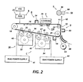
- a reproduction machine in which the present invention finds advantageous use, utilises a charge retentive member in the form of a photoconductive belt 10 mounted for movement past a charging station A, an exposure station B, developer stations C, transfer station D, fusing station E and cleaning station F.
- Belt 10 is entrained about a plurality of rollers 18, 20 and 22.
- Motor 23 rotates roller 20 to advance belt 10 in the direction of arrow 16 to advance successive portions thereof sequentially through the various processing stations disposed about the path of movement thereof.
- a corona discharge device 24 charges the belt 10 to a selectively high uniform positive or negative potential.
- the charged portions of the photoconductive belt surface are advanced through exposure station B.
- the uniformly charged belt surface 10 is exposed to a laser based input and/or output scanning device 25 which causes the photoconductive belt surface to be discharged in accordance with the output from the scanning device.
- the resulting photoconductive belt surface contains both charged-area images and discharged-area images.
- the photoconductive belt surface when exposed at the exposure station B, is discharged to near zero or ground potential in the highlight (i.e. colour other than black) colour parts of the image.
- the photoconductive belt surface is also partially discharged in the background (white) image areas. After passing through the exposure station, the the belt surface contains charged areas and discharged areas which corresponding to two electrostatic latent images and to charged edges outside of the image areas.
- a development system 30 advances developer materials into contact with the electrostatic latent images.
- the development system 30 comprises first and second developer apparatuses 32 and 34.
- the developer apparatus 32 comprises a housing containing a pair of magnetic brush rollers 35 and 36.
- the rollers advance developer material 40 into contact with the discharged areas of the latent images.
- the developer material 40 contains negatively charged color toner. Electrical biasing is accomplished via power supply 41 electrically connected to developer apparatus 32. A DC bias is applied to the rollers 35 and 36 via the power supply 41.
- the developer apparatus 34 comprises a housing containing a pair of magnetic brush rolls 37 and 38.
- the rollers advance developer material 42 into contact with the photoreceptor for developing the charged-area images.
- the developer material 42 contains positively charged black toner for developing the charged areas of the latent images.
- Appropriate electrical biasing is accomplished via power supply 43 electrically connected to developer apparatus 34.
- a DC bias is applied to the rollers 37 and 38 via the bias power supply 43.
- a pre-transfer corona discharge member 56 is provided to condition the toner for effective transfer to a substrate using corona discharge of a desired polarity, either negative or positive.
- Sheets of substrate 58 are advanced to transfer station D from a supply tray, not shown. Sheets are fed from the tray by a sheet feeder, also not shown, and advanced to transfer station D through a corona charging device 60. After transfer, the sheet continues to move in the direction of arrow 62 to fusing station E.
- Fusing station E includes a fuser assembly 64, which permanently affixes the transferred toner powder images to the sheets.
- fuser assembly 64 includes a heated fuser roller 66 adapted to be pressure engaged with a backup roller 68 with the toner powder images contacting fuser roller 66. In this manner, the toner powder image is permanently affixed to the sheet.
- copy sheets After fusing, copy sheets are directed to catch tray, not shown or a finishing station for binding, stapling, collating etc., and removal from the machine by the operator.
- Residual toner and debris remaining on photoconductive belt 10 after each copy is made, may be removed at cleaning station F with a cleaning apparatus 70.
- the photoconductive belt 10 is supported by an acoustic transfer assist device 130.
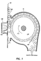
- Figure 1 shows an elevational view of the cleaning apparatus of the present invention.
- the cleaning apparatus 70 comprises a dual polarity, commutated roll 110 that electrostatically attracts (both right and wrong signed) toner, after it has been loosened from the photoconductive belt 10 by the acoustical horn 140.
- the horn 140 may optionally be held in contact with the photoconductive belt 10 by suction.
- the high frequency vibration of the photoconductive belt 10 causes the toner particles 120 to form a particle cloud between the photoconductive belt 10 and the commutated roll 110.
- the voltage potentials on the commutated cleaning roll 110 are adjusted such that a more positive attraction (or negative attraction for wrong sign toner) is felt by the negatively charged toner on the grounded photoconductive belt.
- a positive 250 volt potential on positive commutations of the cleaning roll create a strong attraction of the negatively charged toner setting on the grounded photoconductive belt towards the commutated cleaning roll 110.
- a negative 250 volt potential on the negative commutations of the cleaning roll create a strong attraction of the positively charged (wrong sign) toner towards the commutated cleaning roll.
- the commutated roll 110 attracts and causes both right and wrong sign toner to adhere to its surface as it rotates in a direction shown by arrow 115.
- a scraper blade 150 is placed in contact with the surface of the commutated roll 110 such that as the commutated roll rotates past the scraper blade 150, the particles adhering to the surface of the commutated roll 110 are scraped from the surface into a waste container (not shown).
- a vertical cleaner position allows the toner to "free fall” into a toner collection container due to gravity.
- ATA device 130 yields greater than a 95% transfer efficiency in a cleaner configuration that allows the ATA to be operated at maximum potential.
- the acoustical horn 140 can be driven at maximum potential because toner registration is not a concern. This would allow for larger gaps between the roll 110 and photoconductive belt 10 thus, reducing the need for critical tolerances.
- the distance "x" of the commutated cleaning roll 110 from the surface of the photoconductive belt 10 is chosen to minimize the need for critical tolerances.
- the voltage potentials applied to the commutated cleaning roll are optimized such that the field strength between the commutated roll and the photoconductive belt are at a maximum and the air break down limit is not exceeded.
- the voltage is high enough to create a strong attraction of the toner from the photoconductive belt towards the commutated roll 110 but not strong enough to break down the air between the commutated roll 110 and photoconductive belt 10 and start arcing.
- the voltage applied to the commutated roll 110 is in a range from approximately 100 volts (positive or negative) up to the air breakdown limit of approximately -100 volts.
- the voltage potentials and gap width would be chosen to maximize field strength and minimize the chance of entering the air breakdown limit.
- This non-contact cleaner eliminates motion quality problems, reduces photoconductive belt drag and reduces emissions. In a multi-pass copier (image-on-image), this cleaner would not have to retract from the photoconductive belt like conventional contact cleaners. Thus, reducing UMC (Unit Manufacturing Cost) and increasing reliability of the cleaner.
- the dual polarity, commutated roll of the present invention attracts toner and debris particles loosened into a particle cloud from the photoconductive belt surface by an acoustical horn.
- the particles adhere to the commutated roll, whether right or wrong sign (positively or negatively charged), and are removed form the roll, as the roll rotates, by a scraper blade.
- the particles are collected in a waste container as the particles are removed from the roll surface by the scraper blade.
Landscapes
- Physics & Mathematics (AREA)
- General Physics & Mathematics (AREA)
- Life Sciences & Earth Sciences (AREA)
- Engineering & Computer Science (AREA)
- Environmental & Geological Engineering (AREA)
- Sustainable Development (AREA)
- Cleaning In Electrography (AREA)
Claims (9)
- Vorrichtung (70) zum Entfernen von Teilchen (120) von einem Träger (10), die umfaßt:eine Vorrichtung (140), die mit dem Träger in Verbindung steht und die Teilchen durch Schwingung von dem Träger löst; undein Element (110), das an den Träger angrenzend angeordnet ist und die gelösten Teilchen anzieht, wobei das Element eine Vielzahl von Segmenten enthält und benachbarte Segmente entgegengesetzte Polarität haben, um Teilchen mit entgegengesetzter Polarität anzuziehen.
- Vorrichtung nach Anspruch 1, wobei der Träger eine erste und eine zweite Fläche hat, und wobei die Vorrichtung Schwingungsenergie auf die erste Fläche des Trägers ausübt.
- Vorrichtung nach Anspruch 1 oder 2, wobei das Element eine Walze umfaßt.
- Vorrichtung nach Anspruch 3, wobei die Walze an die zweite Fläche des Trägers angrenzend angeordnet und von ihr beabstandet ist.
- Vorrichtung nach einem der Ansprüche 3 oder 4, wobei es sich bei der Vorrichtung um einen Schalltrichter handelt, der auf die Walze ausgerichtet ist.
- Vorrichtung nach Anspruch 5, wobei der Trichter in Funktion eine Wolke von Teilchen in dem Raum zwischen der Walze und der zweiten Fläche des Trägers erzeugt.
- Vorrichtung nach einem der Ansprüche 3 bis 6, wobei die Vorrichtung des weiteren einen Schaber (150) umfaßt, der mit der Walze in Kontakt kommt, um daran haftende Teilchen zu entfernen.
- Vorrichtung nach einem der vorangehenden Ansprüche, wobei zu den Teilchen negativ geladene Teilchen und positiv geladene Teilchen gehören.
- Vorrichtung nach Anspruch 8, wobei die negativ geladenen Teilchen von den Segmenten der Walze angezogen werden, die auf eine positive Polarität geladen sind, und wobei die positiv geladenen Teilchen von den Segmenten der Walze angezogen werden, die auf eine negative Polarität geladen sind.
Applications Claiming Priority (2)
| Application Number | Priority Date | Filing Date | Title |
|---|---|---|---|
| US08/327,933 US5500969A (en) | 1994-10-24 | 1994-10-24 | Dual polarity commutated roll elctrostatic cleaner with acoustic transfer assist |
| US327933 | 1994-10-24 |
Publications (3)
| Publication Number | Publication Date |
|---|---|
| EP0709751A2 EP0709751A2 (de) | 1996-05-01 |
| EP0709751A3 EP0709751A3 (de) | 1997-10-22 |
| EP0709751B1 true EP0709751B1 (de) | 1999-09-01 |
Family
ID=23278715
Family Applications (1)
| Application Number | Title | Priority Date | Filing Date |
|---|---|---|---|
| EP95307561A Expired - Lifetime EP0709751B1 (de) | 1994-10-24 | 1995-10-24 | Gerät zur Entfernung von Teilchen von einer Oberfläche |
Country Status (4)
| Country | Link |
|---|---|
| US (1) | US5500969A (de) |
| EP (1) | EP0709751B1 (de) |
| JP (1) | JPH08185099A (de) |
| DE (1) | DE69511815T2 (de) |
Families Citing this family (9)
| Publication number | Priority date | Publication date | Assignee | Title |
|---|---|---|---|---|
| JP2644209B2 (ja) * | 1995-04-20 | 1997-08-25 | 日本電気データ機器株式会社 | クリーニング装置 |
| US5634185A (en) * | 1996-06-27 | 1997-05-27 | Xerox Corporation | Removing toner additive films, spots, comets and residual toner on a flexible planar member using ultrasonic vibrational energy |
| US5659849A (en) * | 1996-07-03 | 1997-08-19 | Xerox Corporation | Biased toner collection roll for an ultrasonically assisted cleaning blade |
| US5864741A (en) * | 1997-04-17 | 1999-01-26 | Xerox Corporation | Single brush cleaner with collection roll and ultrasonic cleaning assist |
| US6628568B1 (en) | 2002-03-19 | 2003-09-30 | Bha Group Holdings, Inc. | System and method for verification of acoustic horn performance |
| KR20070011746A (ko) * | 2005-07-21 | 2007-01-25 | 삼성전자주식회사 | 전사벨트방식 화상형성장치 |
| JP4961143B2 (ja) * | 2006-01-30 | 2012-06-27 | 株式会社リコー | 画像形成装置 |
| JP4961142B2 (ja) * | 2006-01-30 | 2012-06-27 | 株式会社リコー | 画像形成装置 |
| US8727832B2 (en) * | 2011-09-27 | 2014-05-20 | HGST Netherlands B.V. | System, method and apparatus for enhanced cleaning and polishing of magnetic recording disk |
Family Cites Families (12)
| Publication number | Priority date | Publication date | Assignee | Title |
|---|---|---|---|---|
| NL286833A (nl) * | 1961-12-27 | 1965-02-25 | Kalle Ag | Inrichting voor het ontwikkelen van elektrostatische beelden |
| US3572923A (en) * | 1968-08-26 | 1971-03-30 | Xerox Corp | Cleaning method and apparatus for electrostatic copying machines |
| US3848994A (en) * | 1973-10-29 | 1974-11-19 | Xerox Corp | Line charge toner cleaning |
| US4111546A (en) * | 1976-08-26 | 1978-09-05 | Xerox Corporation | Ultrasonic cleaning apparatus for an electrostatographic reproducing machine |
| JPS59228956A (ja) * | 1983-06-09 | 1984-12-22 | Fuji Xerox Co Ltd | 粉体粒子捕集用ロ−ル |
| JPS61173282A (ja) * | 1985-01-28 | 1986-08-04 | Minolta Camera Co Ltd | 転写型電子複写機 |
| US4975748A (en) * | 1989-01-09 | 1990-12-04 | Ricoh Company, Ltd. | Method of removing a film from an image carrier |
| US5030999A (en) * | 1989-06-19 | 1991-07-09 | Xerox Corporation | High frequency vibratory enhanced cleaning in electrostatic imaging devices |
| US5065194A (en) * | 1990-05-29 | 1991-11-12 | Eastman Kodak Company | Piezo film cleaner |
| US5025291A (en) * | 1990-07-02 | 1991-06-18 | Zerox Corporation | Edge effect compensation in high frequency vibratory energy producing devices for electrophotographic imaging |
| US5363183A (en) * | 1991-09-06 | 1994-11-08 | Xerox Corporation | Copying machine with device for removing carrier beads from the photoconductive surface |
| US5282008A (en) * | 1991-10-28 | 1994-01-25 | Eastman Kodak Company | Magnetic roller cleaning apparatus |
-
1994
- 1994-10-24 US US08/327,933 patent/US5500969A/en not_active Expired - Lifetime
-
1995
- 1995-10-16 JP JP7266056A patent/JPH08185099A/ja not_active Withdrawn
- 1995-10-24 EP EP95307561A patent/EP0709751B1/de not_active Expired - Lifetime
- 1995-10-24 DE DE69511815T patent/DE69511815T2/de not_active Expired - Fee Related
Also Published As
| Publication number | Publication date |
|---|---|
| EP0709751A2 (de) | 1996-05-01 |
| US5500969A (en) | 1996-03-26 |
| DE69511815D1 (de) | 1999-10-07 |
| EP0709751A3 (de) | 1997-10-22 |
| DE69511815T2 (de) | 2000-02-24 |
| JPH08185099A (ja) | 1996-07-16 |
Similar Documents
| Publication | Publication Date | Title |
|---|---|---|
| EP0366426B1 (de) | Elektrophotographische Vorrichtung mit einer mittels Wechselspannung betriebenen Reinigungseinrichtung | |
| EP0404491B1 (de) | Elektrostatisches Bilderzeugungsgerät | |
| EP0588553B1 (de) | Reinigungsgerät | |
| EP0709751B1 (de) | Gerät zur Entfernung von Teilchen von einer Oberfläche | |
| US6259882B1 (en) | Cleaning brush for non-imaging surfaces in an electrostatographic printer or copier | |
| EP0872782B1 (de) | Reinigungsgerät mit Vibrator | |
| JPH10301409A (ja) | 転写ローラ電気的バイアス制御 | |
| US5970297A (en) | Transfer apparatus and method for removing residual material from a transfer member | |
| EP0147187B1 (de) | Reinigungsgerät für elektrisch ladungsfähige Oberfläche | |
| US6169872B1 (en) | Electrostatic cleaning belt brush | |
| US5659849A (en) | Biased toner collection roll for an ultrasonically assisted cleaning blade | |
| JPH07210053A (ja) | 電子写真装置のクリーニング装置 | |
| US5561513A (en) | Enhanced brush detoning by rotating the detoning roll in the "with" direction | |
| EP1103869A2 (de) | Schaumstoffblock zum Entfernen von elektrostatisch geladenen Teilchen von einer Oberfläche | |
| JPH06118842A (ja) | 画像形成装置 | |
| JP3472037B2 (ja) | 画像形成装置 | |
| JP2003295629A (ja) | 画像形成装置 | |
| JP3228549B2 (ja) | 画像形成装置 | |
| US6690899B2 (en) | Conductive fiber brush cleaner having separate detoning and scavenging zones | |
| JPH05224565A (ja) | 画像形成装置のキャリヤ除去装置 | |
| JP3960217B2 (ja) | 画像形成装置 | |
| JPH05197237A (ja) | 画像形成装置 | |
| JP2003098931A (ja) | クリーニング装置及び画像形成装置 | |
| JPH0980890A (ja) | 電子写真装置 | |
| MXPA98002699A (en) | Single brush cleaner with roller collector and cleaning help ultrason |
Legal Events
| Date | Code | Title | Description |
|---|---|---|---|
| PUAI | Public reference made under article 153(3) epc to a published international application that has entered the european phase |
Free format text: ORIGINAL CODE: 0009012 |
|
| AK | Designated contracting states |
Kind code of ref document: A2 Designated state(s): DE FR GB |
|
| PUAL | Search report despatched |
Free format text: ORIGINAL CODE: 0009013 |
|
| AK | Designated contracting states |
Kind code of ref document: A3 Designated state(s): DE FR GB |
|
| 17P | Request for examination filed |
Effective date: 19980422 |
|
| 17Q | First examination report despatched |
Effective date: 19980624 |
|
| GRAG | Despatch of communication of intention to grant |
Free format text: ORIGINAL CODE: EPIDOS AGRA |
|
| GRAG | Despatch of communication of intention to grant |
Free format text: ORIGINAL CODE: EPIDOS AGRA |
|
| GRAH | Despatch of communication of intention to grant a patent |
Free format text: ORIGINAL CODE: EPIDOS IGRA |
|
| GRAH | Despatch of communication of intention to grant a patent |
Free format text: ORIGINAL CODE: EPIDOS IGRA |
|
| GRAA | (expected) grant |
Free format text: ORIGINAL CODE: 0009210 |
|
| AK | Designated contracting states |
Kind code of ref document: B1 Designated state(s): DE FR GB |
|
| REF | Corresponds to: |
Ref document number: 69511815 Country of ref document: DE Date of ref document: 19991007 |
|
| ET | Fr: translation filed | ||
| PLBE | No opposition filed within time limit |
Free format text: ORIGINAL CODE: 0009261 |
|
| STAA | Information on the status of an ep patent application or granted ep patent |
Free format text: STATUS: NO OPPOSITION FILED WITHIN TIME LIMIT |
|
| 26N | No opposition filed | ||
| REG | Reference to a national code |
Ref country code: GB Ref legal event code: IF02 |
|
| PGFP | Annual fee paid to national office [announced via postgrant information from national office to epo] |
Ref country code: FR Payment date: 20021008 Year of fee payment: 8 |
|
| PGFP | Annual fee paid to national office [announced via postgrant information from national office to epo] |
Ref country code: GB Payment date: 20021023 Year of fee payment: 8 |
|
| PGFP | Annual fee paid to national office [announced via postgrant information from national office to epo] |
Ref country code: DE Payment date: 20021024 Year of fee payment: 8 |
|
| PG25 | Lapsed in a contracting state [announced via postgrant information from national office to epo] |
Ref country code: GB Free format text: LAPSE BECAUSE OF NON-PAYMENT OF DUE FEES Effective date: 20031024 |
|
| PG25 | Lapsed in a contracting state [announced via postgrant information from national office to epo] |
Ref country code: DE Free format text: LAPSE BECAUSE OF NON-PAYMENT OF DUE FEES Effective date: 20040501 |
|
| GBPC | Gb: european patent ceased through non-payment of renewal fee |
Effective date: 20031024 |
|
| PG25 | Lapsed in a contracting state [announced via postgrant information from national office to epo] |
Ref country code: FR Free format text: LAPSE BECAUSE OF NON-PAYMENT OF DUE FEES Effective date: 20040630 |
|
| REG | Reference to a national code |
Ref country code: FR Ref legal event code: ST |