EP0709202A2 - Manufacturing method of ink jet head, ink jet head manufactured by same and ink jet device having ink jet head - Google Patents
Manufacturing method of ink jet head, ink jet head manufactured by same and ink jet device having ink jet head Download PDFInfo
- Publication number
- EP0709202A2 EP0709202A2 EP95117170A EP95117170A EP0709202A2 EP 0709202 A2 EP0709202 A2 EP 0709202A2 EP 95117170 A EP95117170 A EP 95117170A EP 95117170 A EP95117170 A EP 95117170A EP 0709202 A2 EP0709202 A2 EP 0709202A2
- Authority
- EP
- European Patent Office
- Prior art keywords
- ink jet
- jet head
- substrates
- base plate
- supporting member
- Prior art date
- Legal status (The legal status is an assumption and is not a legal conclusion. Google has not performed a legal analysis and makes no representation as to the accuracy of the status listed.)
- Granted
Links
- 238000004519 manufacturing process Methods 0.000 title claims abstract description 17
- 239000000463 material Substances 0.000 claims abstract description 112
- 239000000853 adhesive Substances 0.000 claims abstract description 91
- 230000001070 adhesive effect Effects 0.000 claims abstract description 91
- 239000000758 substrate Substances 0.000 claims abstract description 52
- 230000006872 improvement Effects 0.000 claims abstract description 5
- 238000000034 method Methods 0.000 claims description 28
- 238000004891 communication Methods 0.000 claims description 8
- 238000000016 photochemical curing Methods 0.000 claims description 8
- 230000000694 effects Effects 0.000 claims description 4
- 239000012530 fluid Substances 0.000 claims 5
- 239000000976 ink Substances 0.000 description 81
- 238000007639 printing Methods 0.000 description 16
- 238000012545 processing Methods 0.000 description 13
- 238000002347 injection Methods 0.000 description 12
- 239000007924 injection Substances 0.000 description 12
- 238000001723 curing Methods 0.000 description 9
- 238000010276 construction Methods 0.000 description 7
- 230000008859 change Effects 0.000 description 6
- 230000008569 process Effects 0.000 description 6
- XUIMIQQOPSSXEZ-UHFFFAOYSA-N Silicon Chemical compound [Si] XUIMIQQOPSSXEZ-UHFFFAOYSA-N 0.000 description 5
- 230000015572 biosynthetic process Effects 0.000 description 5
- 239000000835 fiber Substances 0.000 description 5
- 238000005304 joining Methods 0.000 description 5
- 239000007788 liquid Substances 0.000 description 5
- 229910052710 silicon Inorganic materials 0.000 description 5
- 239000010703 silicon Substances 0.000 description 5
- 230000005484 gravity Effects 0.000 description 4
- 238000000465 moulding Methods 0.000 description 4
- 230000008901 benefit Effects 0.000 description 3
- 230000002950 deficient Effects 0.000 description 3
- 238000001514 detection method Methods 0.000 description 3
- 238000003672 processing method Methods 0.000 description 3
- 229920005989 resin Polymers 0.000 description 3
- 239000011347 resin Substances 0.000 description 3
- 239000004753 textile Substances 0.000 description 3
- 239000010409 thin film Substances 0.000 description 3
- 229910052782 aluminium Inorganic materials 0.000 description 2
- XAGFODPZIPBFFR-UHFFFAOYSA-N aluminium Chemical compound [Al] XAGFODPZIPBFFR-UHFFFAOYSA-N 0.000 description 2
- 238000007664 blowing Methods 0.000 description 2
- 230000006835 compression Effects 0.000 description 2
- 238000007906 compression Methods 0.000 description 2
- 230000007423 decrease Effects 0.000 description 2
- 230000008021 deposition Effects 0.000 description 2
- 238000007599 discharging Methods 0.000 description 2
- 239000011521 glass Substances 0.000 description 2
- 238000010438 heat treatment Methods 0.000 description 2
- 238000005259 measurement Methods 0.000 description 2
- 229910052751 metal Inorganic materials 0.000 description 2
- 239000002184 metal Substances 0.000 description 2
- 229920002492 poly(sulfone) Polymers 0.000 description 2
- 230000009467 reduction Effects 0.000 description 2
- 239000007787 solid Substances 0.000 description 2
- 230000002269 spontaneous effect Effects 0.000 description 2
- KXGFMDJXCMQABM-UHFFFAOYSA-N 2-methoxy-6-methylphenol Chemical compound [CH]OC1=CC=CC([CH])=C1O KXGFMDJXCMQABM-UHFFFAOYSA-N 0.000 description 1
- GNFTZDOKVXKIBK-UHFFFAOYSA-N 3-(2-methoxyethoxy)benzohydrazide Chemical compound COCCOC1=CC=CC(C(=O)NN)=C1 GNFTZDOKVXKIBK-UHFFFAOYSA-N 0.000 description 1
- 239000004925 Acrylic resin Substances 0.000 description 1
- 229920000178 Acrylic resin Polymers 0.000 description 1
- FGUUSXIOTUKUDN-IBGZPJMESA-N C1(=CC=CC=C1)N1C2=C(NC([C@H](C1)NC=1OC(=NN=1)C1=CC=CC=C1)=O)C=CC=C2 Chemical compound C1(=CC=CC=C1)N1C2=C(NC([C@H](C1)NC=1OC(=NN=1)C1=CC=CC=C1)=O)C=CC=C2 FGUUSXIOTUKUDN-IBGZPJMESA-N 0.000 description 1
- BVKZGUZCCUSVTD-UHFFFAOYSA-L Carbonate Chemical compound [O-]C([O-])=O BVKZGUZCCUSVTD-UHFFFAOYSA-L 0.000 description 1
- 239000004640 Melamine resin Substances 0.000 description 1
- 229920000877 Melamine resin Polymers 0.000 description 1
- 229920001807 Urea-formaldehyde Polymers 0.000 description 1
- YTAHJIFKAKIKAV-XNMGPUDCSA-N [(1R)-3-morpholin-4-yl-1-phenylpropyl] N-[(3S)-2-oxo-5-phenyl-1,3-dihydro-1,4-benzodiazepin-3-yl]carbamate Chemical compound O=C1[C@H](N=C(C2=C(N1)C=CC=C2)C1=CC=CC=C1)NC(O[C@H](CCN1CCOCC1)C1=CC=CC=C1)=O YTAHJIFKAKIKAV-XNMGPUDCSA-N 0.000 description 1
- 238000005299 abrasion Methods 0.000 description 1
- 238000010521 absorption reaction Methods 0.000 description 1
- PNEYBMLMFCGWSK-UHFFFAOYSA-N aluminium oxide Inorganic materials [O-2].[O-2].[O-2].[Al+3].[Al+3] PNEYBMLMFCGWSK-UHFFFAOYSA-N 0.000 description 1
- 230000033228 biological regulation Effects 0.000 description 1
- 230000005540 biological transmission Effects 0.000 description 1
- 239000000919 ceramic Substances 0.000 description 1
- 238000004140 cleaning Methods 0.000 description 1
- 239000003086 colorant Substances 0.000 description 1
- 238000012937 correction Methods 0.000 description 1
- 230000008878 coupling Effects 0.000 description 1
- 238000010168 coupling process Methods 0.000 description 1
- 238000005859 coupling reaction Methods 0.000 description 1
- 230000003247 decreasing effect Effects 0.000 description 1
- MTHSVFCYNBDYFN-UHFFFAOYSA-N diethylene glycol Chemical compound OCCOCCO MTHSVFCYNBDYFN-UHFFFAOYSA-N 0.000 description 1
- 239000000428 dust Substances 0.000 description 1
- 229920001971 elastomer Polymers 0.000 description 1
- 239000003822 epoxy resin Substances 0.000 description 1
- 238000000227 grinding Methods 0.000 description 1
- 238000013007 heat curing Methods 0.000 description 1
- 230000007246 mechanism Effects 0.000 description 1
- 238000012986 modification Methods 0.000 description 1
- 230000004048 modification Effects 0.000 description 1
- 239000005011 phenolic resin Substances 0.000 description 1
- 229920001568 phenolic resin Polymers 0.000 description 1
- 229920000647 polyepoxide Polymers 0.000 description 1
- 229920000728 polyester Polymers 0.000 description 1
- 229920001721 polyimide Polymers 0.000 description 1
- 239000009719 polyimide resin Substances 0.000 description 1
- 229920005749 polyurethane resin Polymers 0.000 description 1
- 238000012805 post-processing Methods 0.000 description 1
- 238000007781 pre-processing Methods 0.000 description 1
- 230000005855 radiation Effects 0.000 description 1
- 230000001105 regulatory effect Effects 0.000 description 1
- 229910052594 sapphire Inorganic materials 0.000 description 1
- 239000010980 sapphire Substances 0.000 description 1
- 239000000565 sealant Substances 0.000 description 1
- 239000000243 solution Substances 0.000 description 1
- 229920006337 unsaturated polyester resin Polymers 0.000 description 1
- 238000003466 welding Methods 0.000 description 1
Images


Classifications
-
- B—PERFORMING OPERATIONS; TRANSPORTING
- B41—PRINTING; LINING MACHINES; TYPEWRITERS; STAMPS
- B41J—TYPEWRITERS; SELECTIVE PRINTING MECHANISMS, i.e. MECHANISMS PRINTING OTHERWISE THAN FROM A FORME; CORRECTION OF TYPOGRAPHICAL ERRORS
- B41J2/00—Typewriters or selective printing mechanisms characterised by the printing or marking process for which they are designed
- B41J2/005—Typewriters or selective printing mechanisms characterised by the printing or marking process for which they are designed characterised by bringing liquid or particles selectively into contact with a printing material
- B41J2/01—Ink jet
- B41J2/135—Nozzles
- B41J2/16—Production of nozzles
- B41J2/1601—Production of bubble jet print heads
- B41J2/1604—Production of bubble jet print heads of the edge shooter type
-
- B—PERFORMING OPERATIONS; TRANSPORTING
- B41—PRINTING; LINING MACHINES; TYPEWRITERS; STAMPS
- B41J—TYPEWRITERS; SELECTIVE PRINTING MECHANISMS, i.e. MECHANISMS PRINTING OTHERWISE THAN FROM A FORME; CORRECTION OF TYPOGRAPHICAL ERRORS
- B41J2/00—Typewriters or selective printing mechanisms characterised by the printing or marking process for which they are designed
- B41J2/005—Typewriters or selective printing mechanisms characterised by the printing or marking process for which they are designed characterised by bringing liquid or particles selectively into contact with a printing material
- B41J2/01—Ink jet
- B41J2/135—Nozzles
- B41J2/14—Structure thereof only for on-demand ink jet heads
- B41J2/14016—Structure of bubble jet print heads
- B41J2/14024—Assembling head parts
-
- B—PERFORMING OPERATIONS; TRANSPORTING
- B41—PRINTING; LINING MACHINES; TYPEWRITERS; STAMPS
- B41J—TYPEWRITERS; SELECTIVE PRINTING MECHANISMS, i.e. MECHANISMS PRINTING OTHERWISE THAN FROM A FORME; CORRECTION OF TYPOGRAPHICAL ERRORS
- B41J2/00—Typewriters or selective printing mechanisms characterised by the printing or marking process for which they are designed
- B41J2/005—Typewriters or selective printing mechanisms characterised by the printing or marking process for which they are designed characterised by bringing liquid or particles selectively into contact with a printing material
- B41J2/01—Ink jet
- B41J2/135—Nozzles
- B41J2/145—Arrangement thereof
- B41J2/155—Arrangement thereof for line printing
-
- B—PERFORMING OPERATIONS; TRANSPORTING
- B41—PRINTING; LINING MACHINES; TYPEWRITERS; STAMPS
- B41J—TYPEWRITERS; SELECTIVE PRINTING MECHANISMS, i.e. MECHANISMS PRINTING OTHERWISE THAN FROM A FORME; CORRECTION OF TYPOGRAPHICAL ERRORS
- B41J2/00—Typewriters or selective printing mechanisms characterised by the printing or marking process for which they are designed
- B41J2/005—Typewriters or selective printing mechanisms characterised by the printing or marking process for which they are designed characterised by bringing liquid or particles selectively into contact with a printing material
- B41J2/01—Ink jet
- B41J2/135—Nozzles
- B41J2/16—Production of nozzles
- B41J2/1621—Manufacturing processes
- B41J2/1623—Manufacturing processes bonding and adhesion
-
- B—PERFORMING OPERATIONS; TRANSPORTING
- B41—PRINTING; LINING MACHINES; TYPEWRITERS; STAMPS
- B41J—TYPEWRITERS; SELECTIVE PRINTING MECHANISMS, i.e. MECHANISMS PRINTING OTHERWISE THAN FROM A FORME; CORRECTION OF TYPOGRAPHICAL ERRORS
- B41J2/00—Typewriters or selective printing mechanisms characterised by the printing or marking process for which they are designed
- B41J2/005—Typewriters or selective printing mechanisms characterised by the printing or marking process for which they are designed characterised by bringing liquid or particles selectively into contact with a printing material
- B41J2/01—Ink jet
- B41J2/135—Nozzles
- B41J2/16—Production of nozzles
- B41J2/1621—Manufacturing processes
- B41J2/1632—Manufacturing processes machining
-
- B—PERFORMING OPERATIONS; TRANSPORTING
- B41—PRINTING; LINING MACHINES; TYPEWRITERS; STAMPS
- B41J—TYPEWRITERS; SELECTIVE PRINTING MECHANISMS, i.e. MECHANISMS PRINTING OTHERWISE THAN FROM A FORME; CORRECTION OF TYPOGRAPHICAL ERRORS
- B41J2/00—Typewriters or selective printing mechanisms characterised by the printing or marking process for which they are designed
- B41J2/005—Typewriters or selective printing mechanisms characterised by the printing or marking process for which they are designed characterised by bringing liquid or particles selectively into contact with a printing material
- B41J2/01—Ink jet
- B41J2/135—Nozzles
- B41J2/16—Production of nozzles
- B41J2/1621—Manufacturing processes
- B41J2/1637—Manufacturing processes molding
-
- B—PERFORMING OPERATIONS; TRANSPORTING
- B41—PRINTING; LINING MACHINES; TYPEWRITERS; STAMPS
- B41J—TYPEWRITERS; SELECTIVE PRINTING MECHANISMS, i.e. MECHANISMS PRINTING OTHERWISE THAN FROM A FORME; CORRECTION OF TYPOGRAPHICAL ERRORS
- B41J2/00—Typewriters or selective printing mechanisms characterised by the printing or marking process for which they are designed
- B41J2/005—Typewriters or selective printing mechanisms characterised by the printing or marking process for which they are designed characterised by bringing liquid or particles selectively into contact with a printing material
- B41J2/01—Ink jet
- B41J2/135—Nozzles
- B41J2/14—Structure thereof only for on-demand ink jet heads
- B41J2002/14362—Assembling elements of heads
-
- B—PERFORMING OPERATIONS; TRANSPORTING
- B41—PRINTING; LINING MACHINES; TYPEWRITERS; STAMPS
- B41J—TYPEWRITERS; SELECTIVE PRINTING MECHANISMS, i.e. MECHANISMS PRINTING OTHERWISE THAN FROM A FORME; CORRECTION OF TYPOGRAPHICAL ERRORS
- B41J2202/00—Embodiments of or processes related to ink-jet or thermal heads
- B41J2202/01—Embodiments of or processes related to ink-jet heads
- B41J2202/20—Modules
-
- Y—GENERAL TAGGING OF NEW TECHNOLOGICAL DEVELOPMENTS; GENERAL TAGGING OF CROSS-SECTIONAL TECHNOLOGIES SPANNING OVER SEVERAL SECTIONS OF THE IPC; TECHNICAL SUBJECTS COVERED BY FORMER USPC CROSS-REFERENCE ART COLLECTIONS [XRACs] AND DIGESTS
- Y10—TECHNICAL SUBJECTS COVERED BY FORMER USPC
- Y10S—TECHNICAL SUBJECTS COVERED BY FORMER USPC CROSS-REFERENCE ART COLLECTIONS [XRACs] AND DIGESTS
- Y10S29/00—Metal working
- Y10S29/044—Vacuum
-
- Y—GENERAL TAGGING OF NEW TECHNOLOGICAL DEVELOPMENTS; GENERAL TAGGING OF CROSS-SECTIONAL TECHNOLOGIES SPANNING OVER SEVERAL SECTIONS OF THE IPC; TECHNICAL SUBJECTS COVERED BY FORMER USPC CROSS-REFERENCE ART COLLECTIONS [XRACs] AND DIGESTS
- Y10—TECHNICAL SUBJECTS COVERED BY FORMER USPC
- Y10T—TECHNICAL SUBJECTS COVERED BY FORMER US CLASSIFICATION
- Y10T29/00—Metal working
- Y10T29/42—Piezoelectric device making
-
- Y—GENERAL TAGGING OF NEW TECHNOLOGICAL DEVELOPMENTS; GENERAL TAGGING OF CROSS-SECTIONAL TECHNOLOGIES SPANNING OVER SEVERAL SECTIONS OF THE IPC; TECHNICAL SUBJECTS COVERED BY FORMER USPC CROSS-REFERENCE ART COLLECTIONS [XRACs] AND DIGESTS
- Y10—TECHNICAL SUBJECTS COVERED BY FORMER USPC
- Y10T—TECHNICAL SUBJECTS COVERED BY FORMER US CLASSIFICATION
- Y10T29/00—Metal working
- Y10T29/49—Method of mechanical manufacture
- Y10T29/49401—Fluid pattern dispersing device making, e.g., ink jet
Definitions
- the present invention relates to an ink jet head which is elongated by arranging a plurality of element substrates for effecting printing by ejecting liquid, and a manufacturing method therefor. It further relates to a device provided with the ink jet head.
- an ink jet print type is widely used because the noise is low and because the high speed recording is possible.
- an ink jet head wherein thermal energy is applied to the ink by which the state change is produced in the ink, and the ink is ejected by the pressure resulting from thermal-expansion of the resultant gas (bubble jet type), is advantageous in that the responsivity to the print signal is high, and high density arrangement of the ejection outlets is relatively easy.
- an ink jet head of so-called full line type of the bubble jet type wherein ejection outlets and electrothermal transducers are arranged over the entire width of the printing material and an ink jet device having such an ink jet head, are expected as being the ones which permit the high speed printing.
- the above-described advantages can be enjoyed, but another problem arises.
- the arrangement accuracy is significantly influential to the printing quality.
- the arrangement accuracy is determined by the connection between the supporting member and the heater board or by the direct connection between the heater boards, and therefore, the processing accuracy of each construction member has to be strictly controlled. This also reduces the yield.
- the arrangement accuracy decreases with the result of influence to the printing quality.
- a step is formed on the heater forming the heater board with the result of gap in the contact plane between the heater board and the top plate. The gap may bring about cross-talk between adjacent nozzles with the result of improper printing.
- a supporting member for supporting the heater boards have recesses.
- an ink jet head manufacturing method wherein a plurality of substrates provided with ejection energy generating elements for generating energy for ejecting ink, are arranged on a supporting member, and a top plate is mounted on the substrate to cover all of the substrates to form ink flow paths, the improvement residing in that the supporting member is provided with recesses at a supporting portion for supporting the substrates, and an adhesive material is supplied into the recesses, and thereafter, the substrate is placed on the supporting member.
- the heater boards are independently supported by a supporting portion, which is provided with recesses.
- the contact area between the heater boards and the base plate is decreased, so that the step on the heater board resulting from the foreign matter deposited to the contact surfaces is prevented from being formed, and therefore, an ink jet head having high reliability without improper printing such as cross-talk, can be provided.
- Figure 1 is a schematic view showing a construction of elongated ink jet head using a base plate provided with a seating for HB (heater board).
- Figure 2 is an illustration of step occurrence on a heater board by deposition of foreign matter.
- Figure 3 is an illustration of introduction of surplus adhesive material in a groove of the seating.
- Figure 4 is a schematic exploded view of an ink jet head according to a second embodiment of present invention.
- Figure 5 is a schematic view of a base plate used in the second embodiment.
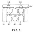
- Figure 6 is an enlarged view of the seating portion of Figure 5.
- Figure 7 is an illustration of manufacturing step of the ink jet head according to the second embodiment.
- Figure 8 is a schematic view of an ink jet head having a through-opening in the base plate functioning as an adhesive material injection portion in Figure 5 embodiment.
- Figure 9 is a schematic exploded view of an ink jet head according to a third embodiment of the present invention. Shows a Figure 10 example of a conventional positioning method when the heater boards are positioned on the base plate.
- Figure 11 shows an example of a conventional positioning method when heater boards are positioned on the base plate.
- Figure 12 shows an example of ink jet device having an ink jet head according to an an embodiment of the present invention.
- Figure 13 is a schematic view wherein heater boards are placed on the base plate in an ink jet head according to embodiment 4 of the present invention.
- Figure 14 is a schematic view showing major portions in Figure 13.
- Figure 15 is a schematic view showing detail of heater board position pose change portion of Figure 13.
- Figure 16 is a sectional view and a sectional view of the neighborhood of the base plate in the device of Figure 13.
- Figure 17 is a sectional view of the base plate of embodiment 4.
- Figure 18 is an illustration of operation of arrangement in the heater boards on the base plate in Figure 17.
- Figure 19 is an illustration of operation of supplying an adhesive material into the opening of the base plate in Figure 17.
- Figure 20 is an illustration of light projection for curing the adhesive material in Figure 19.
- Figure 21 is an illustration of light projection for curing the adhesive material in Figure 19.
- Figure 22 is a schematic view showing a state wherein a heater board is temporarily fixed on the base plate of Figure 17.
- Figure 23 is an enlarged perspective view showing a reference surface for heater board mounting on the base plate.
- Figure 24 is an illustration of operation of applying second adhesive material.
- Figure 1 is a schematic view showing a construction of an elongated ink jet head using a base plate provided with a seating for HB position for.
- a heater board (which will also be called HB) having electrothermal transducer elements for generating thermal energy to eject the ink.
- the HB is of monocrystal silicon, polycrystal silicon, glass, metal or ceramic or the like, and the electrothermal transducer elements are formed on the HB by thin film manufacturing technique or the like.
- Designated by 300 is a base plate for supporting the heater boards, and the base plate 300 is of glass alumina, sapphire, silicon, metal, for example.
- Designated by 310 is a seating functioning as a supporting member for HB positioning on the base plate. The seating supports the HBs independently from one another, and is integral with the base plate in this embodiment.
- Designated by 313 is a sucking opening in the seating 310 portion to assure the position of the HBs.
- Designated by 400 is a wiring substrate electrically connected with the HB to transmit the driving signal from the main assembly of the device, and is provided on the base plate similarly to the HB.
- the wiring substrate 400 and the HB are electrically connected by wire bonding.
- the Wiring substrate 400 is electrically connected with the main assembly of the device by a flexible cable 600, and the flexible cable 600 and the wiring substrate 400 are connected by a connector 700.
- Designated by 200 is a top plate for formation of flow paths by coupling with the HB on the base plate, and the top plate 200 is provided with ejection outlets for ejecting the ink and flow path grooves for forming the flow paths, integrally. It is joined to the HB 100 so that the flow path grooves and said electrothermal transducer elements correspond with each other.
- the materials of the top plate 200 may be any resin material if the grooves can be formed precisely.
- the material exhibits high mechanical strength, dimensional stability and ink-resistant property.
- the material include epoxy resin material, acrylic resin material, diglycol, dialkyl carbonate resin material, unsaturated polyester resin material, polyurethane resin material, polyimide resin material, melamine resin material, phenolic resin, urea resin material or the like. From the standpoint of molding property and liquid-resistant property, polysulfon, polyester polysulfon or the like resin material are desirable.
- the use of the seating in the ink jet head according to an embodiment of the present invention is effective to provide a solution to the problem of the step on the surface of the heater.
- the seating 310 is provided with recesses 311, and the HB100 is supported by the seating 310 at the portions of the seating 310 except for the recesses 311.
- the contact area between the seating 310 and the HB100 can be reduced by the recess 311.Even if foreign matter is deposited on the contacting surface of the HB100 or the base plate 300, most of the foreign matter 315 enters the recess 311, as shown in Figure 2, and therefore, the probability of production of the step of surfaces of the heaters between adjacent HBs is remarkably reduced.
- the HB 100 and the seating 310 are connected by adhesive material. If the adhesive material is provided in the recess 311, the fixing therebetween is assured even if the quantity of the is adhesive material is not so strictly controlled.
- Designated by 313 is a sucking opening for assuring the positioning of the HBs 100 on the seating 310 portion.
- the HBs 100 are attracted through the sucking openings 313 to the base plate 300 to be fixed on the base plate 300 so that the HBs 100 can be maintained with high positional accuracy until the adhesive material is cured.
- the description will be made as to a method for mounting the HB to the base plate provided with the seating and a manufacturing method of the ink jet head.
- a base plate 300 provided with an integral seating 310 shown in Figure 1 is made from an aluminum substrate through a die-cast method.
- a plurality of HBs 100 having an electrothermal transducers on a silicon substrate made through a thin film formation technique are prepared.
- proper amount of of the adhesive material is poured into the recess 311 of the seating 310.
- the adhesive material 50 in the recess 311 is bulged due to its viscosity or surface tension beyond the reference surface of the seating, as shown in Figure 3, a.
- the HB 100 is placed on the position where the adhesive material 50 has been dropped into the recesses thereof, and the HB 100 is attracted through the sucking opening 313 so that the HB 100 is temporarily fixed.
- the adhesive material 50 is attached to the HB 100, as shown in Figure 3, b, and surplus adhesive material 50 enters the space in the recess.
- the adhesive material 50 is not completely cured, and therefore, the position of HB 100 can be corrected if the sucking is eased.
- the adhesive material 50 is cured by heating or the like, thus fixing the HB 100.
- the step on the surface of the heater of the ink jet head of a full line type manufactured through such a method is as small as not more than + ⁇ _1 micron between adjacent HBs.
- Each HB 100 is electrically connected to the wiring substrate 400 by wire bonding, and thereafter, the top plate 200 extended to cover all the HBs 100, is mounted on the HBs 100.
- the top plate 200 is provided with grooves formed by ejection molding to constitute the ink flow paths and ejection outlet plate. By fixing the top plate 200, an ink jet head of full line type is completed.
- Figure 12 shows a construction of an ink jet device having the ink jet head according to the foregoing an embodiment.
- the ink jet device is provided with line type heads 2201a-2201d as shown in Figure 12, and the line type heads 2201a-2201d are fixed in parallel with each other at predetermined intervals in a X direction by a holder 2202.
- 3456 ejection outlets are provided faced down at the intervals of 16 ejection outlets /mm in a line in Y direction to enable the recording over a width of 218mm.
- the heads 2201a-2201d eject recording liquid by thermal energy, and the ejection control is effected by a head driver 2220.
- a head unit is constituted by the heads 2201a- 2201d and the holder 202, and the head unit is movable up and down by a head moving means 224.
- head caps 2203a-2203d are disposed adjacent to the respective heads 2201a-2201d corresondingly thereto.
- Each head cap 2203a-2203d is provided with an ink absorption member such as sponge therein.
- the caps 2203a-2203d are fixed by unshown holder.
- a cap unit is constituted by the holder and the caps 2203a-2203d.
- the cap unit is movable in the X direction by the cap moving means 2225.
- cyan, magenta, yellow, black inks are supplied from ink containers 2204a-2204d through ink supply tubes 2205a-2205d, respectively to permit color recording.
- capillary phenomenon at the head ejection outlet is used, and therefore, the liquid surface of the each ink container 2204a-2204d is lower than the ejection outlet position by a constant distance.
- This device has an electrically chargeable seamless belt 2206 for transporting a recording material in the form of a recording paper 227.
- the belt 2206 is extended along a predetermined path by a driving roller 2207, idle rollers 2209, 2209a and a tension roller 2210, and is connected to the driving roller 2207. It is moved by a belt driving motor 2208 driven by a motor driver 2221.
- the belt 2206 travels right below the ejection outlets of the heads 2201a-2201d. In this embodiment, the downward deflection is suppressed by the fixed supporting member 2226.
- Designated by reference numeral 2217 is a cleaning unit for removing paper dust or the like deposition on the surface of the belt 2206.
- Designated by reference numeral 2212 is a charger for charging the charger, and the charger 2212 is rendered ON and OFF by a charger driver 2222, the recording paper is attracted on the belt 2206 by the electrostatic attraction force produced by the charging.
- pinch rollers 2211 and 2211a for cooperation with the idle rollers 2209 and 2209a to urge the transported recording paper 2227 to the belt 2206.
- Designated by reference numeral 2232 is a sheet feeding cassette, a recording paper 2227 in which is fed out one by one by the rotation of the sheet feeding roller 2216 driven by the motor driver 2223, and is fed in the X direction to a wedge-shaped guide 2213 by a transportation roller 2214 and a pinch roller 2215 driven by the same driver 2223.
- the guide 2213 has a wedge-shaped space to permit deflection of the recording paper.
- Designated by reference numeral 2218 is a sheet discharge tray for receiving the recording paper on which the printing has been completed.
- the control circuit 2219 controls all of the head driver 2220, head moving means 2224, cap moving means 2225, motor driver 2221, 2223, and charger driver 2222.
- Figure 4 is a schematic perspective view of an ink jet head according to a second embodiment of the present invention.
- Figure 5 is a schematic view of a base plate of this embodiment, and
- Figure 6 is an enlarged view of the seating portion of Figure 5.
- the second embodiment of the present invention will be described with a manufacturing step of the ink jet head.
- Figure 7 is an illustration of manufacturing step of the ink jet head in this embodiment.
- a long multi- head using one grooved top plate for 11 heater boards (HBs) are used. The manufacturing method thereof will be described.
- a base plate having projections for PCB positioning and HB supporting portions for supporting the HBs is formed from an aluminum substrate through a die-cast molding.
- the supporting portion is provided with openings for attracting the HBs to fix them temporarily to the recess for the adhesive material injection.
- Figure 5 is a schematic view of a base plate produced through the die-cast molding
- Figure 6 is an enlarged view of the seating portion of Figure 5.
- FIG. 5 and 6 designated by 310 is a HB supporting portion, and 311 is a recess in the HB supporting portion, 312 is an adhesive material injection groove in communication with the recess 311, 313 is a sucking opening, 314 is a positioning projection of the PCB, and 315 is a dimple for communication between the adhesive material injection groove 312 and the recess 311.
- the hatched portion of the base plate and the surface of the supporting portion are abraded or ground. By this, the flatness of the surface of the supporting portion is improved to decrease the probability of occurrences of the step when the HBs are positioned.
- the opposite end portions of the base plate function as the positioning portion relative to the device to improve the accuracy in the assemblying.
- HBs heater boards
- the HBs thus prepared are arranged and correctly positioned on the HB supporting portion of the base plate using positioning tool or the like.
- the HBs thus positioned are fixed temporarily by attraction through the sucking opening by a vacuum tool disposed below the base plate. In this manner each HB is sequentially disposed on the base plate.
- the adhesive material is poured through the adhesive material injection groove in the base plate.
- the adhesive material enters the dimple which is in communication with each recess and the adhesive material injection groove, and it enters each recess by the capillary phenomenon.
- the adhesive material is accumulated in the dimple so that the adhesive material smoothly flows into each recess.
- the adhesive material is spontaneously dried, and the HB is completely fixed.
- the sucking by the vacuum tool is released. If a firmer fixed is desired, the adhesive material may be injected through the sucking opening.
- the base plate and the HB are subjected to grinding to remove step in the HB at the lateral end of the ejection outlet. This is done, because if a step is formed in this portion, cross-talk occurs since the top plate which will be described hereinafter is abutted to the ejection outlet lateral edge.
- the PCB(wiring substrate) is bonded to the base plate with positioning using the positioning projections.
- the predetermined positional relation is established, wherein the electrode pads on the PCB and the electrode pads on the HB correspond respectively.
- the HB and the PCB are electrically connected.
- the conduction check for the wire bonding is carried out.
- a press-contact unit is mounted for the purpose of close contact of the top plate on the HB on the base plate.
- the press-contact unit comprises a leaf spring member for urging the heater board and a leaf spring member for supporting and fixing the leaf spring member.
- the leaf spring member has a plurality of cut-away portion, and is divided into a plurality of urging portions. Each urging portion is provided with a through-opening, into which a jig is inserted to effect regulation and release of the urging force for each urging portion.
- the fixed member is joining with the BP through the PCB, and is fixed by screw or heat crimp or the like.
- the urging force of each urging portion is regulated by the jig.
- the alignment is effected so that the ink flow paths and the ejection energy generating elements correspond to each other, and the top plate is joined to the HB.
- the urging force of the urging portion is released, thus fixing the top plate.
- the release of the urging force of the urging portion (the fixing by the urging portion) is effected from the center portion urging portion toward the opposite ends sequentially.
- the warpage of the top plate can be controlled to permit outward escape of the deflection so that the satisfactory joining state can be assured over the entire HB.
- the jig is all removed from the main assembly of the head.
- An ink supply unit is then fixed to a position of the base plate at each end by welding or the like.
- the ink is supplied to the top plate by the ink supply unit.
- the ink may be supplied in the opposite directions, or may be supplied in one direction to circulate the ink.
- a filter is provided at the connector portion of the ink supply unit to trap bubbles.
- a head cover is mounted so as to cover the base plate, and a sealant is supplied to the top plate joining portion and wire bonding portion through a window formed at a position of the head cover corresponding to the urging portion.
- a sealant is supplied to the top plate joining portion and wire bonding portion through a window formed at a position of the head cover corresponding to the urging portion.
- the adhesive material injection portion is in the form of a groove at the HB position side of the base plate, but it may be a through-opening through the base plate, as shown in Figure 8.
- the ink jet head could effect satisfactory printing over the all area of the width of recording sheet.
- Figure 9 is a schematic exploded view of an ink jet head according to a third embodiment of the present invention.
- seating 3 functioning as a supporting member for HB position is a member separate from the base plate 2.
- the material suitable for high processing accuracy at the reference surface of the seating can be used for the seating, so that the material and processing method appropriate for the respective members are usable. Additionally, even if the processing accuracy of the base plate is poor to a certain extent, the accuracy of the step on the surface of the heater in the heater board is not influenced, and therefore, the cost for the manufacturing of the base plate can be saved, thus permitting cost reduction.
- the manufacturing method of the ink jet head is such that a member constituting the seating is set on a HB arrangement machine, and each HB is bonded to the seating, and thereafter, the seating 3 is fixed on the base plate 2.
- the necessity of the provision of the through-opening in the base plate is eliminated.
- the joining between the seating 3 and the base plate 2 may be effected using any means such as an adhesive material or mechanical means unless the positional accuracy of the HB on the seating is not disturbed.
- the subsequent steps they are the same as embodiment 1 or 2.
- Figure 16 is a top plan view (a) and front view (b) of a device using a first bonding method.
- a heater board / base plate supporting portion on which an attraction portion 1209 for positioning the heater board 1100 on the base plate 1101 is fixed by screws.
- the base plate 1101 is fixed such that a reference surface for mounting the heater board 1100 mounting faces down in the vertical direction. Therefore, the heater board 1100 is fixed to the base plate from the bottom.
- pairs of air introduction portions 1210 are connected to the attraction portion 1209.
- a heater board transported by fingers is attracted to the bottom surface of the base plate by attraction or sucking air produced by a vacuum generator (unshown).
- the attraction portion 1209 is provided with a plurality of openings 1213 for permitting application of a photo-curing adhesive material and for transmitting the light for photo-curing of the bonding material.
- the shape of the opening 1213 may be a simple circular hole. However, in this embodiment, it is in the form of an elongated hole to permit transmission of a larger quantity of light for the photo-curing.
- the reason for the orientation of the base plate 1101 to provide the downward facing of the mounting reference surface of the heater board 1100 is that when the adhesive material for fixing the base plate to the heater board is applied by a dispenser, the adhesive material is easily ejected from the dispenser in the vertical direction, and the adhesive material is sufficiently expanded in the adhesive material injection opening 213 formed in the base plate.
- Figure 23 is an enlarged schematic view of the base plate reference surface for the heater board mounting.
- Figure 17 is a sectional view adjacent the heater board mounting portion of the base plate.
- the base plate 1101 is provided, as shown in Figure 23, with a pair of heater board attraction opening 1201 1201a and 1201b at a front portion of the reference surface (ejection outlet side), and a first adhesive material application opening 1200.
- the a number of of the heater board attraction openings 1201 and the number of the first adhesive material application openings 1200 are the same as the number of of the heater boards mounted on the base plate.
- the heater board attraction opening 1201 of the base plate is in communicatin with attraction grooves 1214a and 1214b formed in the reference surface for the heater board mounting to increase the attraction area.
- the pair of the heater board attraction openings 1201 are symmetrically arranged. This is effective to avoid movement of the heater board during the second adhesive material curing to enhance the bonded state. Only one of them may be employed when the accuracy may be slightly poor.
- the first adhesive material application opening 1200 is provided adjacent the center of gravity of the heater board. This is because the first adhesive material is for the temporary fixing of the heater board. With the first adhesive material alone, sufficient bonding strength is not assured, and therefore, the opening diameter may be small as long as the minimum bonding strength for fixing the heater board until the second adhesive material application process is provided.
- the first adhesive material application opening 1200 is adjacent the center of gravity of the heater board.
- the heater board attraction reference surface (mounting reference surface) is finished to a smooth surface by abrasion or the like, to prevent reduction of the attraction force by leakage upon attraction of the heater board and to prevent the applied adhesive material from being sucked into the attraction opening.
- the reference surface for the heater board mounting at the backside of the reference surface for the heater board mounting is provided with a second adhesive material filling groove 1218, and a part thereof has second adhesive material injection groove 1217a and 1217b.
- the heater board 1100 is being placed by fingers on the base plate 1101 fixed to the heater board / base plate supporting portion 1102.
- the finger 1302 are effective to hold the heater board by attraction. By the attraction of the heater formation surface of the heater board, the liability of the fingers contacting to the heater board already positioned, upon the heater board mounting, is avoided, thus improving the yield.
- a rubber pad 1005 is used at the attraction air supply connection portion with the base plate to prevent leakage.
- the heater board 1100 is supplied from a heater board supply portion (unshown) to a heater board grip portion 1106, and is transported to a heater board position measurement portion 1104 while the heater board 1100 is kept on the heater board grip portion 1106.
- a heater board position / pose change portion 1105 for supporting the heater board grip portion 1106 is moved to provide a predetermined position and pose of the heater board 1100.
- the base plate 1101 is supplied from a base plate supply portion (unshown) to a heater board / base plate supporting portion 1102 and is attracted by air sucking by negative pressure air introduction portion 1211.
- the heater board / base plate supporting portion 1102 attracting the base plate 1101 is moved to a base plate positioning and transporting portion 1103.
- the base plate 1101 is abutted to abutments 1203 and 1204, and is fixed by references 1206 and 1212.in the vertical direction, a vertical abutment reference 1202 of the base plate 1101 is pushed up and abutted to the heater board / base plate supporting portion by a fixed portion 1205 for vertical base plate positioning.
- the base plate 1101 is abutted to the reference of the base plate positioning and transporting portion 1103 so that it is cramped at the correct position.
- the correct positioning is accomplished irrespective of the positional accuracy of the plurality of heater board / base plate supporting portion. So, the heater board 1100 in the arrangement position positioning by the heater board position / pose change portion 1105 with a pose, is adjusted only to she abutting reference of the base plate positioning and transporting portion 1103 having only one positioning reference.
- the base plate positioning and transporting portion 1103 carrying the heater board / base plate supporting portion 1102 is moved to a predetermined position in the direction of the arrangement to carry the first heater board.
- the heater board position pose change portion 1105 gripping the heater board 1100 with the corrected pose and position, lands on the heater board 1100 on the base plate 1101.
- the landing of the heater board 1100 is detected, and the vertical direction position upon the landing is detected.
- Figure 15 is a schematic view of a landing portion to the base plate 1101.
- 1302 is a finger for griping the heater board 1100
- 1303 is a support column connected by a rotational shaft to rotate the finger 1302 by the contact between the heater board 1100 and the base plate 1101
- 1304 is a contact detection sensor for detecting the finger 1302 rotating by the contact between the heater board 1100 and the base plate 1101.
- the finger 1302, support column 1303 and contact detection sensor 1304 are carried on a movement portion 1301 for moving the heater board 1100 in the vertical direction (heater board / base plate contact direction).
- the heater board 1100 moved to a predetermined position and pose by the heater board position/pose change portion 1105 is disposed beforehand at a position not contacting to the base plate 1101 in the vertical direction. After the pose and position are determined, the heater board 1100 is moved by pose and position the vertical direction driver 1300 in the vertical direction. When the heater board 1100 and the base plate 1101 are contacted, the finger 1302 rotates about the support column 1303, and the landing is detected by the contact detection sensor 1304. The vertical direction movement position at this time is stored, and the stored data is compared with the data upon the next landing of the heater board 1100, and if the difference is larger than a predetermined level, improperness is discriminated.
- the heater board 1100 landed on the base plate 1101 is supported on the base plate 1101 by the negative pressure air supplied from the outside through the heater board attraction opening 1201 of the base plate, attraction portion 1209 of the heater board / base plate supporting portion 1102, and a portion of the outside negative pressure air introduction portion 1210 for the first heater board attraction.
- the adhesive material is supplied from dispenser 1107 as the adhesive material filling portion through the adhesive material filling hole 1213 of the heater board / base plate supporting portion 1102 and the adhesive material application opening 1200 of the base plate 1101 to prepare for the bonding between the heater board 1100 and the base plate 1101.
- Figure 19 shows the adhesive material filling, wherein designated by 1107a is a cylinder containing the adhesive material; 1107b is a needle at the end of the dispenser 1107.
- the needle of the dispenser 1107 is inserted into the adhesive material filling hole 1213 of the attraction portion 1209 and the adhesive material application opening 1200 of base plate 1101, and the first adhesive material is ejected adjacent the center portion of the opening when the tip end of the needle is at 0.5mm approx. away from the heater board.
- the heater board supporting portion 1106 receives a heater board 1100 from the heater board supply portion (not shown).
- the base plate positioning and transporting portion 1103 moves to a position for positioning and fixing the second heater board 1100, while supporting the first heater board 1100 on the base plate 1101 by the negative pressure air.
- the second heater board is placed, positioned and supported. In this manner, the attraction of the heater board and the adhesive material filling is repeated for the predetermined a number of times equal to the number of the heater boards on the single base plate.
- the base plate now carrying the predetermined a number of of heater boards positioned, attracted with the adhesive material supplied is transported to a discharging position by the base plate positioning and transporting portion or means1103 together with the heater board / base plate supporting portion 1102, and is exposed to the light for the curing of the bonding material by a transporting means (not shown).
- the photo-curing adhesive material is exposed to ultraviolet radiation 1227 through the opening 1213 by a light projecting device set to the opening 1213.
- a fiber diameter is large, as shown in Figure 20, a part of the beams 1227a is cut by the attraction portion 1209.
- a fine adjustment mechanism is provided so as to provide a maximum illuminance. If the fiber diameter is small as shown in Figure 12, the fiber 1228 may be inserted into the opening 1213 of the attraction portion 1209. At this time, the fiber 1228 may be moved vertically, or the base plate side may be moved vertically.
- the heater board and the base plate are temporarily bonded with each other by the adhesive material curing ( Figure 22).
- the adhesive material curing Figure 22.
- the heater board and the base plate are fixed by the temporary bonding, the attraction between the heater board and the base plate by the negative pressure is released, and the base plate is removed from the heater board / base plate supporting portion. Then, it is fed to a permanent adhesive material filling portion (not shown) for the permanent bonding where the second adhesive material is supplied cured.
- the following advantage is provided.
- another heater board / base plate supporting portion is operated to discharging the base plate having finished the photo-curing of the temporary adhesive material and the temporary bonding by the heater board / base plate supporting portion 1102, and to supply another base plate from the base plate supply portion for the next processing.
- the curing process of the temporary adhesive material is carried out, after the temporary adhesive material filling steps for all heater boards are completed, in the photo-curing process portion at a different position.
- the photo-curing for the first heater board is carried out while the second heater board is positioned, after the positioning, attraction and temporary bonding material supplied, are carried out for the first heater board.
- Figure 24 illustrates application of the second adhesive material and the base plate fixed on a second heater board / base plate supporting portion 1220 to apply the second adhesive material.
- the base plate 1101 is reverted, and it is supported on the heater board / base plate supporting portion 220 at the reference position with heater board 1100 at the top.
- the supporting method may be any, for example, screw fixing, finger clamping or the like is usable.
- the second heater board / base plate supporting portion 1220 is inclined at a proper angle ⁇ to facilitate supply of the adhesive material into the second adhesive material filling groove 1218 formed between the base plate and the heater board.
- the second adhesive material flows into the adhesive material filling groove against the surface tension adjacent the adhesive material injection groove 1218 by the gravity. If the angle ⁇ is too large (approaching to 90 o ), the second dispenser 1221 and the base plate are interfered. If it is too small (approaching 0 o ), it becomes difficult for the second adhesive material to overcome the surface tension.
- the angle is preferably 30 o - 60 o approx.
- the second adhesive material (spontaneous curing type or heat curing type) is supplied to the injection grooves 1217a and 1217b in the base plate by the second dispenser 1221.
- the second adhesive material is then flows into the second adhesive material filling groove 1218 between the base plate and the heater board by the gravity. Since the height of the second adhesive material filling groove 1218 is very small, the capillary phenomenon facilitate the flow.
- the second adhesive material is received by the second adhesive material filling groove 1218 in approx. 10 sec after the supply. Thereafter, it flows by the capillary phenomenon, and therefore, the base plate may be made horizontal. It is removed from the second heater board / base plate supporting portion 1220 to permit spontaneous curing. By injecting the second adhesive material into the heater board attraction opening 1201, the bonding of the heater board is further assured.
- different heater board / base plate supporting portions 1220 are used for the first and second bonding processes. However, if the heater board / base plate supporting portion 1220 is driven by NC or the like, for example, to restore the horizontal position after the completion of the first process, by which all the process are automated.
- the temporary bonding is carried out with the heater board is attracted. Therefore, there is no need of keeping the base plate on the jig until the adhesive material is cured, and therefore, the manufacturing at the time of between can be reduced significantly.
- the positioning accuracy of the heater boards is influential to the printing property, and therefore, very high positioning accuracy is required.
- the positioning accuracy here includes the accuracy in the step on the heater surface, the accuracies in ejection side end surface of the heater board and the intervals such as center pitch between heater boards.
- the positions of the heaters and the positions of the ejection outlet end surfaces are measured through non-contact method before the heater board is positioned. Among non-contact methods, image processing is used.
- the image processing method will be described.
- the steps of the image processing method are as follows.
- the arrangement accuracy on the seating is not more than ⁇ 2 microns.
- Figure 10 shows an example of a conventional positioning method. Designated by 7 is a mechanical abutment using cylinder or the like, and 8 is an abutment pin. The abutting portion 7 is driven by a cylinder or the like, and the heater board 1 is abutted to the pin 8 to effect the positioning of the heater board 1. However, with this method, a tipping may occur in the heater board. According to this embodiment, the positioning method as shown in Figure 11 is used. In this Figure, designated by 9 is a compression air blowing portion, and 10 is an ejection outlet, and ejection outlet is a sucking portion.
- the compression air (0.1-0.15kgf/cm2) is supplied to the blowing portion 9, and it is ejected through the ejection outlet 10 to the heater board 1. Additionally, the sucking operation is effected in the sucking portion 11. The operation is repeated several times within 1.5 sec, and the positioning operation is carried out. With this positioning method, the heater board is floated by 0.3-0.5mm during the positioning operation, the heater board is not damaged. With this positioning method, the reproducibility within ⁇ 5 microns is accomplished, so as to permit the stabilized transportation to the image processing area.
- the present invention is applicable to the case of using a plurality of ink jet heads using inks having different colors or inks having different densities.
- the ink jet head of the present invention is usable with a color ink jet device having a plurality of ink jet heads correspondingly to a plurality of color inks.
- the ink has been liquid. However, it may be solid ink under the room temperature if it is liquefied at a temperature above the room temperature.
- the ink may be the one which is liquefied upon application of the print signal.
- the ink may be the one which is solid but is liquefied by heating.
- the present invention is usable for a textile printing device or a textile printing system including a pre-processing apparatus and a post-processing apparatus, wherein the demand for the elongated ink jet head is high.
- a long ink jet head without print non-uniformity with high image quality with high resolution is possible in the textile printing device.
- an ink jet head manufacturing method wherein a plurality of substrates provided with ejection energy generating elements for generating energy for ejecting ink, are arranged on a supporting member, and a top plate is mounted on the substrate to cover all of the substrates to form ink flow paths, the improvement residing in that the supporting member is provided with recesses at a supporting portion for supporting the substrates, and an adhesive material is supplied into the recesses, and thereafter, the substrate is placed on the supporting member.
Abstract
Description
- The present invention relates to an ink jet head which is elongated by arranging a plurality of element substrates for effecting printing by ejecting liquid, and a manufacturing method therefor. It further relates to a device provided with the ink jet head.
- Recently, an ink jet print type is widely used because the noise is low and because the high speed recording is possible. Among various types of ink jet printers, an ink jet head wherein thermal energy is applied to the ink by which the state change is produced in the ink, and the ink is ejected by the pressure resulting from thermal-expansion of the resultant gas (bubble jet type), is advantageous in that the responsivity to the print signal is high, and high density arrangement of the ejection outlets is relatively easy.
- Recently, the data amount to be printed out increases. Particularly, when graphic data are to be printed out, the demand for the high speed print is increasing because the data amount in huge in that case.
- Accordingly, an ink jet head of so-called full line type of the bubble jet type wherein ejection outlets and electrothermal transducers are arranged over the entire width of the printing material and an ink jet device having such an ink jet head, are expected as being the ones which permit the high speed printing.
- As for such a full line type ink jet head, a method wherein all of the electrothermal transducers ate formed in one substrate (heater board). However, in that case, if only one electrothermal transducer of the electrothermal transducers is defective, the entire substrate is not usable, with the result of very low yield. So, in a conventional full line type ink jet head, a plurality of heater boards having electrothermal transducers are combined. An a plurality of electrothermal transducers each having a relatively small number of electrothermal transducers such as 32-128 transducers, are supported on a supporting member at intervals matching the arrangement density of the nozzle. By doing so, even if one electrothermal transducer is defective, one heater heater board having the defective electrothermal transducer is exchanged. Additionally, the size of the heater board per se is small so that the manufacturing of the heater board per se is easy. Accordingly, the yield is remarkably improved. Such a structure is proposed in Japanese Laid Open Patent Application No. HEI- 2-212162, for example.
- By using the construction, the above-described advantages can be enjoyed, but another problem arises. With the above described construction, since a plurality of of heater boards are arranged in a supporting member, the arrangement accuracy is significantly influential to the printing quality. Conventionally, the arrangement accuracy is determined by the connection between the supporting member and the heater board or by the direct connection between the heater boards, and therefore, the processing accuracy of each construction member has to be strictly controlled. This also reduces the yield. When foreign matter is present between the construction members, the arrangement accuracy decreases with the result of influence to the printing quality. When the foreign matter is deposited between the heater board and the base plate, a step is formed on the heater forming the heater board with the result of gap in the contact plane between the heater board and the top plate. The gap may bring about cross-talk between adjacent nozzles with the result of improper printing.
- Accordingly, it is a principal object of the present invention to provide stabilized printing without cross-talk by preventing gap formation between the heater board and the top plate. According to an aspect of the present invention, a supporting member for supporting the heater boards have recesses.
- More particularly, there is provided an ink jet head manufacturing method wherein a plurality of substrates provided with ejection energy generating elements for generating energy for ejecting ink, are arranged on a supporting member, and a top plate is mounted on the substrate to cover all of the substrates to form ink flow paths, the improvement residing in that the supporting member is provided with recesses at a supporting portion for supporting the substrates, and an adhesive material is supplied into the recesses, and thereafter, the substrate is placed on the supporting member.
- According to this aspect, the heater boards are independently supported by a supporting portion, which is provided with recesses. Thus, the contact area between the heater boards and the base plate is decreased, so that the step on the heater board resulting from the foreign matter deposited to the contact surfaces is prevented from being formed, and therefore, an ink jet head having high reliability without improper printing such as cross-talk, can be provided.
- These and other objects, features and advantages of the present invention will become more apparent upon a consideration of the following description of the preferred embodiments of the present invention taken in conjunction with the accompanying drawings.
- Figure 1 is a schematic view showing a construction of elongated ink jet head using a base plate provided with a seating for HB (heater board).
- Figure 2 is an illustration of step occurrence on a heater board by deposition of foreign matter.
- Figure 3 is an illustration of introduction of surplus adhesive material in a groove of the seating.
- Figure 4 is a schematic exploded view of an ink jet head according to a second embodiment of present invention. Figure 5 is a schematic view of a base plate used in the second embodiment.
- Figure 6 is an enlarged view of the seating portion of Figure 5.
- Figure 7 is an illustration of manufacturing step of the ink jet head according to the second embodiment.
- Figure 8 is a schematic view of an ink jet head having a through-opening in the base plate functioning as an adhesive material injection portion in Figure 5 embodiment.
- Figure 9 is a schematic exploded view of an ink jet head according to a third embodiment of the present invention. Shows a Figure 10 example of a conventional positioning method when the heater boards are positioned on the base plate.
- Figure 11 shows an example of a conventional positioning method when heater boards are positioned on the base plate.
- Figure 12 shows an example of ink jet device having an ink jet head according to an an embodiment of the present invention.
- Figure 13 is a schematic view wherein heater boards are placed on the base plate in an ink jet head according to embodiment 4 of the present invention.
- Figure 14 is a schematic view showing major portions in Figure 13.
- Figure 15 is a schematic view showing detail of heater board position pose change portion of Figure 13.
- Figure 16 is a sectional view and a sectional view of the neighborhood of the base plate in the device of Figure 13.
- Figure 17 is a sectional view of the base plate of embodiment 4.
- Figure 18 is an illustration of operation of arrangement in the heater boards on the base plate in Figure 17.
- Figure 19 is an illustration of operation of supplying an adhesive material into the opening of the base plate in Figure 17.
- Figure 20 is an illustration of light projection for curing the adhesive material in Figure 19. Figure 21 is an illustration of light projection for curing the adhesive material in Figure 19. Figure 22 is a schematic view showing a state wherein a heater board is temporarily fixed on the base plate of Figure 17.
- Figure 23 is an enlarged perspective view showing a reference surface for heater board mounting on the base plate.
- Figure 24 is an illustration of operation of applying second adhesive material.
- Referring to the accompanying drawings, the embodiments of the present invention will be described.
- Figure 1 is a schematic view showing a construction of an elongated ink jet head using a base plate provided with a seating for HB position for.
- In Figure 1, designated by 100 is a heater board (which will also be called HB) having electrothermal transducer elements for generating thermal energy to eject the ink. The HB is of monocrystal silicon, polycrystal silicon, glass, metal or ceramic or the like, and the electrothermal transducer elements are formed on the HB by thin film manufacturing technique or the like. Designated by 300 is a base plate for supporting the heater boards, and the
base plate 300 is of glass alumina, sapphire, silicon, metal, for example. Designated by 310 is a seating functioning as a supporting member for HB positioning on the base plate. The seating supports the HBs independently from one another, and is integral with the base plate in this embodiment. By precisely forming the portions corresponding to the HBs of the seating, they can be used as rough index when the HBs are positioned thereon. Designated by 313 is a sucking opening in theseating 310 portion to assure the position of the HBs. Designated by 400 is a wiring substrate electrically connected with the HB to transmit the driving signal from the main assembly of the device, and is provided on the base plate similarly to the HB. Thewiring substrate 400 and the HB are electrically connected by wire bonding. TheWiring substrate 400 is electrically connected with the main assembly of the device by aflexible cable 600, and theflexible cable 600 and thewiring substrate 400 are connected by aconnector 700. Designated by 200 is a top plate for formation of flow paths by coupling with the HB on the base plate, and thetop plate 200 is provided with ejection outlets for ejecting the ink and flow path grooves for forming the flow paths, integrally. It is joined to theHB 100 so that the flow path grooves and said electrothermal transducer elements correspond with each other. - The materials of the
top plate 200 may be any resin material if the grooves can be formed precisely. Preferably, the material exhibits high mechanical strength, dimensional stability and ink-resistant property. Examples of the material include epoxy resin material, acrylic resin material, diglycol, dialkyl carbonate resin material, unsaturated polyester resin material, polyurethane resin material, polyimide resin material, melamine resin material, phenolic resin, urea resin material or the like. From the standpoint of molding property and liquid-resistant property, polysulfon, polyester polysulfon or the like resin material are desirable. - The use of the seating in the ink jet head according to an embodiment of the present invention is effective to provide a solution to the problem of the step on the surface of the heater. The
seating 310 is provided withrecesses 311, and the HB100 is supported by theseating 310 at the portions of theseating 310 except for therecesses 311. The contact area between theseating 310 and the HB100 can be reduced by the recess 311.Even if foreign matter is deposited on the contacting surface of the HB100 or thebase plate 300, most of theforeign matter 315 enters therecess 311, as shown in Figure 2, and therefore, the probability of production of the step of surfaces of the heaters between adjacent HBs is remarkably reduced. Usually, theHB 100 and theseating 310 are connected by adhesive material. If the adhesive material is provided in therecess 311, the fixing therebetween is assured even if the quantity of the is adhesive material is not so strictly controlled. - Designated by 313 is a sucking opening for assuring the positioning of the
HBs 100 on theseating 310 portion. TheHBs 100 are attracted through the suckingopenings 313 to thebase plate 300 to be fixed on thebase plate 300 so that theHBs 100 can be maintained with high positional accuracy until the adhesive material is cured. - The description will be made as to a method for mounting the HB to the base plate provided with the seating and a manufacturing method of the ink jet head.
- First, a
base plate 300 provided with anintegral seating 310 shown in Figure 1 is made from an aluminum substrate through a die-cast method. On the other hand, a plurality ofHBs 100 having an electrothermal transducers on a silicon substrate made through a thin film formation technique, are prepared. Subsequently, proper amount of of the adhesive material is poured into therecess 311 of theseating 310. At this time, theadhesive material 50 in therecess 311 is bulged due to its viscosity or surface tension beyond the reference surface of the seating, as shown in Figure 3, a. Then, theHB 100 is placed on the position where theadhesive material 50 has been dropped into the recesses thereof, and theHB 100 is attracted through the suckingopening 313 so that theHB 100 is temporarily fixed. At this time, theadhesive material 50 is attached to theHB 100, as shown in Figure 3, b, and surplusadhesive material 50 enters the space in the recess. With this state, theadhesive material 50 is not completely cured, and therefore, the position ofHB 100 can be corrected if the sucking is eased. When the position of theHB 100 is firmly determined, theadhesive material 50 is cured by heating or the like, thus fixing theHB 100. The step on the surface of the heater of the ink jet head of a full line type manufactured through such a method is as small as not more than +∼_1 micron between adjacent HBs. EachHB 100 is electrically connected to thewiring substrate 400 by wire bonding, and thereafter, thetop plate 200 extended to cover all theHBs 100, is mounted on theHBs 100. Thetop plate 200 is provided with grooves formed by ejection molding to constitute the ink flow paths and ejection outlet plate. By fixing thetop plate 200, an ink jet head of full line type is completed. - When the printing operation is carried out actually using the ink jet head of this this embodiment, satisfactory print was provided over the entire width of the printing sheets.
- The description will be made as to an ink jet device suitably usable with the ink jet head of this invention.
- Figure 12 shows a construction of an ink jet device having the ink jet head according to the foregoing an embodiment.
- The ink jet device is provided with line type heads 2201a-2201d as shown in Figure 12, and the line type heads 2201a-2201d are fixed in parallel with each other at predetermined intervals in a X direction by a
holder 2202. On the bottom surface of eachhead 2201a-2201d, 3456 ejection outlets are provided faced down at the intervals of 16 ejection outlets /mm in a line in Y direction to enable the recording over a width of 218mm. - The
heads 2201a-2201d eject recording liquid by thermal energy, and the ejection control is effected by ahead driver 2220. - A head unit is constituted by the
heads 2201a- 2201d and the holder 202, and the head unit is movable up and down by a head moving means 224. - Below the
heads 2201a-2201d, head caps 2203a-2203d are disposed adjacent to therespective heads 2201a-2201d corresondingly thereto. Eachhead cap 2203a-2203d is provided with an ink absorption member such as sponge therein. - The
caps 2203a-2203d are fixed by unshown holder. A cap unit is constituted by the holder and thecaps 2203a-2203d. The cap unit is movable in the X direction by thecap moving means 2225. - To the
heads 2201a-2201d, cyan, magenta, yellow, black inks are supplied fromink containers 2204a-2204d throughink supply tubes 2205a-2205d, respectively to permit color recording. - For the ink supply, capillary phenomenon at the head ejection outlet is used, and therefore, the liquid surface of the each
ink container 2204a-2204d is lower than the ejection outlet position by a constant distance. - This device has an electrically chargeable
seamless belt 2206 for transporting a recording material in the form of a recording paper 227. - The
belt 2206 is extended along a predetermined path by a drivingroller 2207,idle rollers tension roller 2210, and is connected to the drivingroller 2207. It is moved by abelt driving motor 2208 driven by amotor driver 2221. - The
belt 2206 travels right below the ejection outlets of theheads 2201a-2201d. In this embodiment, the downward deflection is suppressed by the fixed supportingmember 2226. - Designated by
reference numeral 2217 is a cleaning unit for removing paper dust or the like deposition on the surface of thebelt 2206. - Designated by
reference numeral 2212 is a charger for charging the charger, and thecharger 2212 is rendered ON and OFF by acharger driver 2222, the recording paper is attracted on thebelt 2206 by the electrostatic attraction force produced by the charging. - Before and after the
charger 2212, there are providedpinch rollers idle rollers recording paper 2227 to thebelt 2206. - Designated by
reference numeral 2232 is a sheet feeding cassette, arecording paper 2227 in which is fed out one by one by the rotation of thesheet feeding roller 2216 driven by themotor driver 2223, and is fed in the X direction to a wedge-shapedguide 2213 by atransportation roller 2214 and apinch roller 2215 driven by thesame driver 2223. Theguide 2213 has a wedge-shaped space to permit deflection of the recording paper. - Designated by
reference numeral 2218 is a sheet discharge tray for receiving the recording paper on which the printing has been completed. - The
control circuit 2219 controls all of thehead driver 2220,head moving means 2224, cap movingmeans 2225,motor driver charger driver 2222. - Figure 4 is a schematic perspective view of an ink jet head according to a second embodiment of the present invention. Figure 5 is a schematic view of a base plate of this embodiment, and Figure 6 is an enlarged view of the seating portion of Figure 5.
- The second embodiment of the present invention will be described with a manufacturing step of the ink jet head.
- Figure 7 is an illustration of manufacturing step of the ink jet head in this embodiment. In this embodiment, a long multi- head using one grooved top plate for 11 heater boards (HBs), are used. The manufacturing method thereof will be described.
- First, a base plate having projections for PCB positioning and HB supporting portions for supporting the HBs, is formed from an aluminum substrate through a die-cast molding. The supporting portion is provided with openings for attracting the HBs to fix them temporarily to the recess for the adhesive material injection. Figure 5 is a schematic view of a base plate produced through the die-cast molding, and Figure 6 is an enlarged view of the seating portion of Figure 5. In Figures 5 and 6, designated by 310 is a HB supporting portion, and 311 is a recess in the HB supporting portion, 312 is an adhesive material injection groove in communication with the
recess material injection groove 312 and therecess 311. - The hatched portion of the base plate and the surface of the supporting portion are abraded or ground. By this, the flatness of the surface of the supporting portion is improved to decrease the probability of occurrences of the step when the HBs are positioned. The opposite end portions of the base plate function as the positioning portion relative to the device to improve the accuracy in the assemblying.
- While the base plate is manufactured, a plurality of heater boards (HBs) each having electrothermal transducer elements manufactured through the thin film formation technique on a silicon substrate, are prepared.
- Then, the HBs thus prepared, are arranged and correctly positioned on the HB supporting portion of the base plate using positioning tool or the like. The HBs thus positioned are fixed temporarily by attraction through the sucking opening by a vacuum tool disposed below the base plate. In this manner each HB is sequentially disposed on the base plate.
- Then, the adhesive material is poured through the adhesive material injection groove in the base plate. The adhesive material enters the dimple which is in communication with each recess and the adhesive material injection groove, and it enters each recess by the capillary phenomenon. By the provision of the dimple at a position for communicatin between the adhesive material injection groove and the each recess, the adhesive material is accumulated in the dimple so that the adhesive material smoothly flows into each recess. Thereafter, the adhesive material is spontaneously dried, and the HB is completely fixed. Then, the sucking by the vacuum tool is released. If a firmer fixed is desired, the adhesive material may be injected through the sucking opening.
- After the completion of the position and fixing of the HB, the base plate and the HB are subjected to grinding to remove step in the HB at the lateral end of the ejection outlet. This is done, because if a step is formed in this portion, cross-talk occurs since the top plate which will be described hereinafter is abutted to the ejection outlet lateral edge.
- Then, the PCB(wiring substrate) is bonded to the base plate with positioning using the positioning projections. By doing so, the predetermined positional relation is established, wherein the electrode pads on the PCB and the electrode pads on the HB correspond respectively. By wire bonding between the electrode pads on the PCB and the electrode pads of the HB, the HB and the PCB are electrically connected. Contemporaneously, the conduction check for the wire bonding is carried out.
- Subsequently, a press-contact unit is mounted for the purpose of close contact of the top plate on the HB on the base plate. The press-contact unit comprises a leaf spring member for urging the heater board and a leaf spring member for supporting and fixing the leaf spring member. The leaf spring member has a plurality of cut-away portion, and is divided into a plurality of urging portions. Each urging portion is provided with a through-opening, into which a jig is inserted to effect regulation and release of the urging force for each urging portion.
- When the press-contact unit is fixed to the BP, the fixed member is joining with the BP through the PCB, and is fixed by screw or heat crimp or the like.
- In order to fix the top plate on the heater board, the urging force of each urging portion is regulated by the jig.
- After sufficient space is provided on the heater board in this manner, the alignment is effected so that the ink flow paths and the ejection energy generating elements correspond to each other, and the top plate is joined to the HB.
- Then, the urging force of the urging portion is released, thus fixing the top plate. The release of the urging force of the urging portion (the fixing by the urging portion) is effected from the center portion urging portion toward the opposite ends sequentially. By releasing the urging force in this manner, the warpage of the top plate can be controlled to permit outward escape of the deflection so that the satisfactory joining state can be assured over the entire HB. After the release of the urging force of the urging portion, the jig is all removed from the main assembly of the head.
- An ink supply unit is then fixed to a position of the base plate at each end by welding or the like. The ink is supplied to the top plate by the ink supply unit. The ink may be supplied in the opposite directions, or may be supplied in one direction to circulate the ink. A filter is provided at the connector portion of the ink supply unit to trap bubbles.
- Finally, a head cover is mounted so as to cover the base plate, and a sealant is supplied to the top plate joining portion and wire bonding portion through a window formed at a position of the head cover corresponding to the urging portion. Thus, the ink jet head is completed.
- In this embodiment, the adhesive material injection portion is in the form of a groove at the HB position side of the base plate, but it may be a through-opening through the base plate, as shown in Figure 8.
- Similarly to embodiment 1, the ink jet head could effect satisfactory printing over the all area of the width of recording sheet.
- Figure 9 is a schematic exploded view of an ink jet head according to a third embodiment of the present invention.
- In Figure 9, seating 3 functioning as a supporting member for HB position is a member separate from the base plate 2. By the use of the separate seating 3 and base plate 2, the material suitable for high processing accuracy at the reference surface of the seating can be used for the seating, so that the material and processing method appropriate for the respective members are usable. Additionally, even if the processing accuracy of the base plate is poor to a certain extent, the accuracy of the step on the surface of the heater in the heater board is not influenced, and therefore, the cost for the manufacturing of the base plate can be saved, thus permitting cost reduction.
- When the seating is formed on the base plate, the manufacturing method of the ink jet head is such that a member constituting the seating is set on a HB arrangement machine, and each HB is bonded to the seating, and thereafter, the seating 3 is fixed on the base plate 2. By first mounting the HB to the seating, the necessity of the provision of the through-opening in the base plate is eliminated. The joining between the seating 3 and the base plate 2 may be effected using any means such as an adhesive material or mechanical means unless the positional accuracy of the HB on the seating is not disturbed. As the subsequent steps, they are the same as embodiment 1 or 2.
- A fourth embodiment will be described.
- Figure 16 is a top plan view (a) and front view (b) of a device using a first bonding method.
- In Figure 16, designated by 1102 is a heater board / base plate supporting portion, on which an
attraction portion 1209 for positioning theheater board 1100 on thebase plate 1101 is fixed by screws. Thebase plate 1101 is fixed such that a reference surface for mounting theheater board 1100 mounting faces down in the vertical direction. Therefore, theheater board 1100 is fixed to the base plate from the bottom. - To the
attraction portion 1209, pairs ofair introduction portions 1210 are connected. A heater board transported by fingers is attracted to the bottom surface of the base plate by attraction or sucking air produced by a vacuum generator (unshown). Theattraction portion 1209 is provided with a plurality ofopenings 1213 for permitting application of a photo-curing adhesive material and for transmitting the light for photo-curing of the bonding material. The shape of theopening 1213 may be a simple circular hole. However, in this embodiment, it is in the form of an elongated hole to permit transmission of a larger quantity of light for the photo-curing. - The reason for the orientation of the
base plate 1101 to provide the downward facing of the mounting reference surface of theheater board 1100 is that when the adhesive material for fixing the base plate to the heater board is applied by a dispenser, the adhesive material is easily ejected from the dispenser in the vertical direction, and the adhesive material is sufficiently expanded in the adhesive material injection opening 213 formed in the base plate. - Referring to Figures 17 and 23, the description will be made as to the details of the base plate of this embodiment. Figure 23 is an enlarged schematic view of the base plate reference surface for the heater board mounting. Figure 17 is a sectional view adjacent the heater board mounting portion of the base plate.
- The
base plate 1101 is provided, as shown in Figure 23, with a pair of heaterboard attraction opening 1201 1201a and 1201b at a front portion of the reference surface (ejection outlet side), and a first adhesivematerial application opening 1200. The a number of of the heaterboard attraction openings 1201 and the number of the first adhesivematerial application openings 1200 are the same as the number of of the heater boards mounted on the base plate. In order to improve the attraction force for the heater board, the heaterboard attraction opening 1201 of the base plate is in communicatin withattraction grooves 1214a and 1214b formed in the reference surface for the heater board mounting to increase the attraction area. In this embodiment, the pair of the heaterboard attraction openings 1201 are symmetrically arranged. This is effective to avoid movement of the heater board during the second adhesive material curing to enhance the bonded state. Only one of them may be employed when the accuracy may be slightly poor. - Here, the first adhesive
material application opening 1200 is provided adjacent the center of gravity of the heater board. This is because the first adhesive material is for the temporary fixing of the heater board. With the first adhesive material alone, sufficient bonding strength is not assured, and therefore, the opening diameter may be small as long as the minimum bonding strength for fixing the heater board until the second adhesive material application process is provided. In order to fix the heater board with the minimum bonding strength, the first adhesivematerial application opening 1200 is adjacent the center of gravity of the heater board. The heater board attraction reference surface (mounting reference surface) is finished to a smooth surface by abrasion or the like, to prevent reduction of the attraction force by leakage upon attraction of the heater board and to prevent the applied adhesive material from being sucked into the attraction opening. - The reference surface for the heater board mounting at the backside of the reference surface for the heater board mounting is provided with a second adhesive
material filling groove 1218, and a part thereof has second adhesivematerial injection groove - Referring to Figure 18, the description will be made as to a portion for attracting the heater board to the base plate.
- In Figure 18, the
heater board 1100 is being placed by fingers on thebase plate 1101 fixed to the heater board / baseplate supporting portion 1102. - The
finger 1302 are effective to hold the heater board by attraction. By the attraction of the heater formation surface of the heater board, the liability of the fingers contacting to the heater board already positioned, upon the heater board mounting, is avoided, thus improving the yield. Arubber pad 1005 is used at the attraction air supply connection portion with the base plate to prevent leakage. - Referring to Figures 13-15, the description will be made as to, operation when the heater boards are positioned and fixed to the base plate.
- In Figure 13, the
heater board 1100 is supplied from a heater board supply portion (unshown) to a heaterboard grip portion 1106, and is transported to a heater boardposition measurement portion 1104 while theheater board 1100 is kept on the heaterboard grip portion 1106. In the heater boardposition measurement portion 1104, a heater board position /pose change portion 1105 for supporting the heaterboard grip portion 1106 is moved to provide a predetermined position and pose of theheater board 1100. - On the other hand, the
base plate 1101 is supplied from a base plate supply portion (unshown) to a heater board / baseplate supporting portion 1102 and is attracted by air sucking by negative pressureair introduction portion 1211. The heater board / baseplate supporting portion 1102 attracting thebase plate 1101, is moved to a base plate positioning and transportingportion 1103. At this time, thebase plate 1101 is abutted toabutments references 1206 and 1212.in the vertical direction, avertical abutment reference 1202 of thebase plate 1101 is pushed up and abutted to the heater board / base plate supporting portion by a fixedportion 1205 for vertical base plate positioning. Thus, thebase plate 1101 is abutted to the reference of the base plate positioning and transportingportion 1103 so that it is cramped at the correct position. Thus, the correct positioning is accomplished irrespective of the positional accuracy of the plurality of heater board / base plate supporting portion. So, theheater board 1100 in the arrangement position positioning by the heater board position /pose change portion 1105 with a pose, is adjusted only to she abutting reference of the base plate positioning and transportingportion 1103 having only one positioning reference. - The base plate positioning and transporting
portion 1103 carrying the heater board / baseplate supporting portion 1102 is moved to a predetermined position in the direction of the arrangement to carry the first heater board. With this state, the heater board position posechange portion 1105 gripping theheater board 1100 with the corrected pose and position, lands on theheater board 1100 on thebase plate 1101. At this time, the landing of theheater board 1100 is detected, and the vertical direction position upon the landing is detected. - Figure 15 is a schematic view of a landing portion to the
base plate 1101. - In Figure 15, designated by 1302 is a finger for griping the
heater board 1100; 1303 is a support column connected by a rotational shaft to rotate thefinger 1302 by the contact between theheater board 1100 and thebase plate 1101; 1304 is a contact detection sensor for detecting thefinger 1302 rotating by the contact between theheater board 1100 and thebase plate 1101. Thefinger 1302,support column 1303 andcontact detection sensor 1304 are carried on amovement portion 1301 for moving theheater board 1100 in the vertical direction (heater board / base plate contact direction). - The description will be made as to the joining operation of the
heater board 1100 to thebase plate 1101. - The
heater board 1100 moved to a predetermined position and pose by the heater board position/pose change portion 1105 is disposed beforehand at a position not contacting to thebase plate 1101 in the vertical direction. After the pose and position are determined, theheater board 1100 is moved by pose and position thevertical direction driver 1300 in the vertical direction. When theheater board 1100 and thebase plate 1101 are contacted, thefinger 1302 rotates about thesupport column 1303, and the landing is detected by thecontact detection sensor 1304. The vertical direction movement position at this time is stored, and the stored data is compared with the data upon the next landing of theheater board 1100, and if the difference is larger than a predetermined level, improperness is discriminated. Theheater board 1100 landed on thebase plate 1101 is supported on thebase plate 1101 by the negative pressure air supplied from the outside through the heaterboard attraction opening 1201 of the base plate,attraction portion 1209 of the heater board / baseplate supporting portion 1102, and a portion of the outside negative pressureair introduction portion 1210 for the first heater board attraction. - After the heater board is thus supported, the adhesive material is supplied from
dispenser 1107 as the adhesive material filling portion through the adhesivematerial filling hole 1213 of the heater board / baseplate supporting portion 1102 and the adhesivematerial application opening 1200 of thebase plate 1101 to prepare for the bonding between theheater board 1100 and thebase plate 1101. - Figure 19 shows the adhesive material filling, wherein designated by 1107a is a cylinder containing the adhesive material; 1107b is a needle at the end of the
dispenser 1107. The needle of thedispenser 1107 is inserted into the adhesivematerial filling hole 1213 of theattraction portion 1209 and the adhesivematerial application opening 1200 ofbase plate 1101, and the first adhesive material is ejected adjacent the center portion of the opening when the tip end of the needle is at 0.5mm approx. away from the heater board. - Subsequently, in order to position and fix the
second heater board 1100, the heaterboard supporting portion 1106 receives aheater board 1100 from the heater board supply portion (not shown). The base plate positioning and transportingportion 1103 moves to a position for positioning and fixing thesecond heater board 1100, while supporting thefirst heater board 1100 on thebase plate 1101 by the negative pressure air. Similarly to the first heater board, the second heater board is placed, positioned and supported. In this manner, the attraction of the heater board and the adhesive material filling is repeated for the predetermined a number of times equal to the number of the heater boards on the single base plate. - The base plate now carrying the predetermined a number of of heater boards positioned, attracted with the adhesive material supplied is transported to a discharging position by the base plate positioning and transporting portion or means1103 together with the heater board / base
plate supporting portion 1102, and is exposed to the light for the curing of the bonding material by a transporting means (not shown). - Referring to Figures 20 and 21, the exposure will be described. After the
dispenser 1107 is retracted, the photo-curing adhesive material is exposed toultraviolet radiation 1227 through theopening 1213 by a light projecting device set to theopening 1213. When a fiber diameter is large, as shown in Figure 20, a part of the beams 1227a is cut by theattraction portion 1209. In view of this, at the portion for holding thefibers 1226, a fine adjustment mechanism is provided so as to provide a maximum illuminance. If the fiber diameter is small as shown in Figure 12, thefiber 1228 may be inserted into theopening 1213 of theattraction portion 1209. At this time, thefiber 1228 may be moved vertically, or the base plate side may be moved vertically. - In this manner, the heater board and the base plate are temporarily bonded with each other by the adhesive material curing (Figure 22). When the heater board and the base plate are fixed by the temporary bonding, the attraction between the heater board and the base plate by the negative pressure is released, and the base plate is removed from the heater board / base plate supporting portion. Then, it is fed to a permanent adhesive material filling portion (not shown) for the permanent bonding where the second adhesive material is supplied cured.
- By the provision of a plurality of heater board / base plate supporting portions, the following advantage is provided. During the heater board being positioned, attracted and the temporary adhesive material filling being effected, another heater board / base plate supporting portion is operated to discharging the base plate having finished the photo-curing of the temporary adhesive material and the temporary bonding by the heater board / base
plate supporting portion 1102, and to supply another base plate from the base plate supply portion for the next processing. - In this embodiment, the curing process of the temporary adhesive material is carried out, after the temporary adhesive material filling steps for all heater boards are completed, in the photo-curing process portion at a different position. However, it is a possible alternative that the photo-curing for the first heater board is carried out while the second heater board is positioned, after the positioning, attraction and temporary bonding material supplied, are carried out for the first heater board.
- The description will be made as to supply and curing of the second adhesive material.
- Figure 24 illustrates application of the second adhesive material and the base plate fixed on a second heater board / base
plate supporting portion 1220 to apply the second adhesive material. - The
base plate 1101 is reverted, and it is supported on the heater board / base plate supporting portion 220 at the reference position withheater board 1100 at the top. The supporting method may be any, for example, screw fixing, finger clamping or the like is usable. - The second heater board / base
plate supporting portion 1220 is inclined at a proper angle θ to facilitate supply of the adhesive material into the second adhesivematerial filling groove 1218 formed between the base plate and the heater board. By this angle of thebase plate 1101, the second adhesive material flows into the adhesive material filling groove against the surface tension adjacent the adhesivematerial injection groove 1218 by the gravity. If the angle θ is too large (approaching to 90o), thesecond dispenser 1221 and the base plate are interfered. If it is too small (approaching 0o), it becomes difficult for the second adhesive material to overcome the surface tension. For these reasons, the angle is preferably 30o - 60o approx. - The second adhesive material (spontaneous curing type or heat curing type) is supplied to the
injection grooves second dispenser 1221. The second adhesive material is then flows into the second adhesivematerial filling groove 1218 between the base plate and the heater board by the gravity. Since the height of the second adhesivematerial filling groove 1218 is very small, the capillary phenomenon facilitate the flow. - The second adhesive material is received by the second adhesive
material filling groove 1218 in approx. 10 sec after the supply. Thereafter, it flows by the capillary phenomenon, and therefore, the base plate may be made horizontal. It is removed from the second heater board / baseplate supporting portion 1220 to permit spontaneous curing. By injecting the second adhesive material into the heaterboard attraction opening 1201, the bonding of the heater board is further assured. - Through the above-described steps, the positioning of the heater boards and fixing thereof are completed.
- In this embodiment, different heater board / base
plate supporting portions 1220 are used for the first and second bonding processes. However, if the heater board / baseplate supporting portion 1220 is driven by NC or the like, for example, to restore the horizontal position after the completion of the first process, by which all the process are automated. - As described in the foregoing, in this embodiment, the temporary bonding is carried out with the heater board is attracted. Therefore, there is no need of keeping the base plate on the jig until the adhesive material is cured, and therefore, the manufacturing at the time of between can be reduced significantly.
- When an elongated ink jet head is manufactured by arranging a plurality of heater board, the positioning accuracy of the heater boards is influential to the printing property, and therefore, very high positioning accuracy is required. The positioning accuracy here includes the accuracy in the step on the heater surface, the accuracies in ejection side end surface of the heater board and the intervals such as center pitch between heater boards. In this embodiment, in order to enhance the positioning or arrangement accuracy of the heater boards, the positions of the heaters and the positions of the ejection outlet end surfaces are measured through non-contact method before the heater board is positioned. Among non-contact methods, image processing is used.
- The image processing method will be described.
- The steps of the image processing method are as follows.
- (1) transporting the heater board to an image processing area.
- (2) confirming the center heater of the heater board by the image processing.
- (3) calculating an inclination of the heater board simultaneously with (2).
- (4) confirming the ejection side end surfaces of the heater board by the image processing.
- (5) making correction on the basis of the data obtained through steps (2) - (3), and placing the heater board on the seating with alignment of the center pitch and the heater board ejection side end surface.
- By the use of the image processing, the arrangement accuracy on the seating is not more than ± 2 microns.
- For the proper function of the image processing, the assured transportation to the image processing area is desirable. So, before the image processing, positioning is carried out to assure the proper transportation. Figure 10 shows an example of a conventional positioning method. Designated by 7 is a mechanical abutment using cylinder or the like, and 8 is an abutment pin. The abutting portion 7 is driven by a cylinder or the like, and the heater board 1 is abutted to the
pin 8 to effect the positioning of the heater board 1. However, with this method, a tipping may occur in the heater board. According to this embodiment, the positioning method as shown in Figure 11 is used. In this Figure, designated by 9 is a compression air blowing portion, and 10 is an ejection outlet, and ejection outlet is a sucking portion. First, the compression air (0.1-0.15kgf/cm²) is supplied to the blowingportion 9, and it is ejected through theejection outlet 10 to the heater board 1. Additionally, the sucking operation is effected in the sucking portion 11. The operation is repeated several times within 1.5 sec, and the positioning operation is carried out. With this positioning method, the heater board is floated by 0.3-0.5mm during the positioning operation, the heater board is not damaged. With this positioning method, the reproducibility within ±5 microns is accomplished, so as to permit the stabilized transportation to the image processing area. - In the foregoing description, a monochromatic ink jet device or ink jet head has been dealt with, but the present invention is applicable to the case of using a plurality of ink jet heads using inks having different colors or inks having different densities. The ink jet head of the present invention is usable with a color ink jet device having a plurality of ink jet heads correspondingly to a plurality of color inks. In the foregoing, the ink has been liquid. However, it may be solid ink under the room temperature if it is liquefied at a temperature above the room temperature. Since the ink per se is heated to a temperature of not less than 30oC and not more than 70oC usually for the purpose of providing proper viscosity, the ink may be the one which is liquefied upon application of the print signal. The ink may be the one which is solid but is liquefied by heating.
- The present invention is usable for a textile printing device or a textile printing system including a pre-processing apparatus and a post-processing apparatus, wherein the demand for the elongated ink jet head is high. A long ink jet head without print non-uniformity with high image quality with high resolution is possible in the textile printing device.
- Additionally, with the ink jet head, a facsimile machine, a copying machine, a printer or the like is substantially free of the image disturbance. While the invention has been described with reference to the structures disclosed herein, it is not confined to the details set forth and this application is intended to cover such modifications or changes as may come within the purpose of the improvements or the scope of the following claims.
- In an ink jet head manufacturing method wherein a plurality of substrates provided with ejection energy generating elements for generating energy for ejecting ink, are arranged on a supporting member, and a top plate is mounted on the substrate to cover all of the substrates to form ink flow paths, the improvement residing in that the supporting member is provided with recesses at a supporting portion for supporting the substrates, and an adhesive material is supplied into the recesses, and thereafter, the substrate is placed on the supporting member.
Claims (21)
- In an ink jet head manufacturing method wherein a plurality of substrates provided with ejection energy generating elements for generating energy for ejecting ink, are arranged on a supporting member, and a top plate is mounted on the substrate to cover all of the substrates to form ink flow paths, the improvement residing in that the supporting member is provided with recesses at a supporting portion for supporting the substrates, and an adhesive material is supplied into the recesses, and thereafter, the substrate is placed on the supporting member.
- An method according to Claim 1, wherein the supporting member is provided with openings correspondingly to the substrates at the supporting portion, wherein the substrates are sucked through the openings to effect temporary fixed of the substrates.
- An method according to Claim 1, wherein the adhesive material is supplied into the recesses after placing of the substrate on the supporting portion.
- An method according to Claim 3, wherein the supporting member is provided with interconnection grooves in fluid communication with the recesses, and wherein the adhesive material is supplied to the recesses through the interconnection groove.
- An method according to Claim 2, wherein the substrate is temporarily fixed by photo-curing adhesive material which is supplied through an adhesive material inlet in the supporting member during the sucking operations.
- An ink jet head comprising:
a plurality of substrates having ejection energy generating elements for generating energy of ejecting ink;
a supporting member for supporting said plurality of substrates;
a top plate for covering all of said plurality of substrates, said top plate being coupled with said substrates to form ink flow paths;
wherein said supporting member has a recess in a surface supporting the substrates. - An ink jet head according to Claim 6, &i& the supporting member is provided with openings correspondingly to the substrates at the supporting portion.
- An ink jet head according to Claim 6, wherein the supporting member is provided with interconnection grooves in fluid communication with the recesses.
- An ink jet head according to Claim 8, wherein said interconnection groove is provided with a dimple in fluid communication with said recesses.
- An ink jet head according to Claim 6, wherein said supporting portion and said supporting member are constituted by separate members.
- an ink jet head according to Claim 6, wherein said supporting portion is integral with said supporting member.
- An ink jet head according to Claim 7, wherein a plurality of the openings are provided for each substrate.
- An ink jet head according to Claim 6, wherein said ink jet head is a full line type ink jet head.
- An ink jet apparatus comprising:
an ink jet head including a plurality of substrates having ejection energy generating elements for generating energy of ejecting ink; a supporting member for supporting said plurality of substrates; a top plate for covering all of said plurality of substrates, said top plate being coupled with said substrates to form ink flow paths; wherein said supporting member has a recess in a surface supporting the substrates; and
transporting means for feeding a recording material for receiving the ink ejected by said ink jet head. - An apparatus according to Claim 14, wherein the supporting member is provided with openings correspondingly to the substrates at the supporting portion.
- An apparatus according to Claim 14, wherein the supporting member is provided with interconnection grooves in fluid communication with the recesses.
- An apparatus according to Claim 16, wherein said interconnection groove is provided with a dimple in fluid communication with said recesses.
- An apparatus according to Claim 14, wherein said supporting portion and said supporting member are constituted by separate members.
- An apparatus according to Claim 14, wherein said supporting portion is integral with said supporting member.
- An apparatus according to Claim 15, wherein a plurality of the openings are provided for each substrate.
- An apparatus according to Claim 14, wherein said ink jet head is a full line type ink jet head.
Applications Claiming Priority (6)
| Application Number | Priority Date | Filing Date | Title |
|---|---|---|---|
| JP267057/94 | 1994-10-31 | ||
| JP26705794 | 1994-10-31 | ||
| JP26705794 | 1994-10-31 | ||
| JP28161895 | 1995-10-30 | ||
| JP28161895 | 1995-10-30 | ||
| JP281618/95 | 1995-10-31 |
Publications (3)
| Publication Number | Publication Date |
|---|---|
| EP0709202A2 true EP0709202A2 (en) | 1996-05-01 |
| EP0709202A3 EP0709202A3 (en) | 1997-04-16 |
| EP0709202B1 EP0709202B1 (en) | 2002-07-03 |
Family
ID=26547703
Family Applications (1)
| Application Number | Title | Priority Date | Filing Date |
|---|---|---|---|
| EP95117170A Expired - Lifetime EP0709202B1 (en) | 1994-10-31 | 1995-10-31 | Manufacturing method of ink jet head, ink jet head manufactured by same and ink jet device having ink jet head |
Country Status (7)
| Country | Link |
|---|---|
| US (2) | US5826333A (en) |
| EP (1) | EP0709202B1 (en) |
| KR (1) | KR0156449B1 (en) |
| CN (1) | CN1058660C (en) |
| AT (1) | ATE220005T1 (en) |
| AU (1) | AU691036B2 (en) |
| DE (1) | DE69527246T2 (en) |
Cited By (3)
| Publication number | Priority date | Publication date | Assignee | Title |
|---|---|---|---|---|
| EP0819536A2 (en) * | 1996-07-09 | 1998-01-21 | Canon Kabushiki Kaisha | Liquid discharging head, method for manufacturing such liquid discharging head, head cartridge and liquid discharging apparatus |
| EP1172217A3 (en) * | 2000-07-10 | 2003-12-03 | Canon Kabushiki Kaisha | Ink jet recording head and producing method for the same |
| EP1767366A3 (en) * | 2004-01-30 | 2008-09-17 | Hewlett-Packard Development Company, L.P. | Fluid ejection head assembly |
Families Citing this family (43)
| Publication number | Priority date | Publication date | Assignee | Title |
|---|---|---|---|---|
| AU775428B2 (en) * | 1996-06-07 | 2004-07-29 | Canon Kabushiki Kaisha | Liquid discharging head, liquid discharging apparatus and printing system |
| DE69728082T2 (en) * | 1996-06-07 | 2005-01-20 | Canon K.K. | Liquid ejection head, liquid ejection device and printing system |
| US6257703B1 (en) * | 1996-07-31 | 2001-07-10 | Canon Kabushiki Kaisha | Ink jet recording head |
| US6786420B1 (en) | 1997-07-15 | 2004-09-07 | Silverbrook Research Pty. Ltd. | Data distribution mechanism in the form of ink dots on cards |
| US6803989B2 (en) | 1997-07-15 | 2004-10-12 | Silverbrook Research Pty Ltd | Image printing apparatus including a microcontroller |
| US6618117B2 (en) | 1997-07-12 | 2003-09-09 | Silverbrook Research Pty Ltd | Image sensing apparatus including a microcontroller |
| US6362868B1 (en) * | 1997-07-15 | 2002-03-26 | Silverbrook Research Pty Ltd. | Print media roll and ink replaceable cartridge |
| US6948794B2 (en) | 1997-07-15 | 2005-09-27 | Silverbrook Reserach Pty Ltd | Printhead re-capping assembly for a print and demand digital camera system |
| US6879341B1 (en) | 1997-07-15 | 2005-04-12 | Silverbrook Research Pty Ltd | Digital camera system containing a VLIW vector processor |
| US6624848B1 (en) | 1997-07-15 | 2003-09-23 | Silverbrook Research Pty Ltd | Cascading image modification using multiple digital cameras incorporating image processing |
| US6985207B2 (en) | 1997-07-15 | 2006-01-10 | Silverbrook Research Pty Ltd | Photographic prints having magnetically recordable media |
| AUPO850597A0 (en) | 1997-08-11 | 1997-09-04 | Silverbrook Research Pty Ltd | Image processing method and apparatus (art01a) |
| US6690419B1 (en) | 1997-07-15 | 2004-02-10 | Silverbrook Research Pty Ltd | Utilising eye detection methods for image processing in a digital image camera |
| AUPO802797A0 (en) | 1997-07-15 | 1997-08-07 | Silverbrook Research Pty Ltd | Image processing method and apparatus (ART54) |
| US7110024B1 (en) | 1997-07-15 | 2006-09-19 | Silverbrook Research Pty Ltd | Digital camera system having motion deblurring means |
| US7705891B2 (en) | 1997-07-15 | 2010-04-27 | Silverbrook Research Pty Ltd | Correction of distortions in digital images |
| US5950309A (en) * | 1998-01-08 | 1999-09-14 | Xerox Corporation | Method for bonding a nozzle plate to an ink jet printhead |
| CN1074357C (en) * | 1998-02-26 | 2001-11-07 | 李韫言 | Front jetting single-chip integrated hot steam ink-jet printing head |
| JP2000079693A (en) | 1998-06-26 | 2000-03-21 | Canon Inc | Ink jet print head and manufacture thereof |
| AUPP702098A0 (en) | 1998-11-09 | 1998-12-03 | Silverbrook Research Pty Ltd | Image creation method and apparatus (ART73) |
| AUPQ056099A0 (en) | 1999-05-25 | 1999-06-17 | Silverbrook Research Pty Ltd | A method and apparatus (pprint01) |
| US7304750B2 (en) * | 1999-12-17 | 2007-12-04 | Nektar Therapeutics | Systems and methods for non-destructive mass sensing |
| US6705691B2 (en) | 2000-01-14 | 2004-03-16 | Canon Kabushiki Kaisha | Ink-jet printing method and ink-jet printer |
| US6499823B2 (en) | 2000-06-15 | 2002-12-31 | Canon Kabushiki Kaisha | Ink jet recording head having substrate and ceiling plate base pressed together by base plate and ink supply member |
| JP2002292868A (en) * | 2001-03-28 | 2002-10-09 | Ricoh Co Ltd | Liquid drop ejection head, ink cartridge and ink jet recorder |
| JP2003237083A (en) * | 2002-02-15 | 2003-08-26 | Canon Inc | Liquid jet recording head, and liquid jet recorder with the same |
| JP4332416B2 (en) * | 2003-12-12 | 2009-09-16 | キヤノン株式会社 | Inkjet recording head |
| US7425052B2 (en) * | 2005-02-28 | 2008-09-16 | Silverbrook Research Pty Ltd | Printhead assembly having improved adhesive bond strength |
| JP4963555B2 (en) * | 2005-04-28 | 2012-06-27 | キヤノン株式会社 | Inkjet recording head |
| US7600850B2 (en) * | 2006-03-01 | 2009-10-13 | Lexmark International, Inc. | Internal vent channel in ejection head assemblies and methods relating thereto |
| JP4895358B2 (en) | 2006-05-16 | 2012-03-14 | キヤノン株式会社 | Inkjet recording head |
| JP2008049531A (en) * | 2006-08-23 | 2008-03-06 | Canon Inc | Inkjet recording head |
| JP5188158B2 (en) * | 2006-12-15 | 2013-04-24 | キヤノン株式会社 | Method for manufacturing ink jet recording head |
| US8523323B2 (en) * | 2008-05-23 | 2013-09-03 | Fujifilm Corporation | Method and apparatus for mounting a fluid ejection module |
| JP4880647B2 (en) * | 2008-07-01 | 2012-02-22 | 東京エレクトロン株式会社 | Organic EL film forming apparatus and vapor deposition apparatus |
| JP2010052149A (en) * | 2008-08-26 | 2010-03-11 | Canon Inc | Method for manufacturing recording head |
| JP6433263B2 (en) | 2014-01-14 | 2018-12-05 | キヤノン株式会社 | Method for manufacturing liquid discharge head |
| KR20160109071A (en) | 2015-03-09 | 2016-09-21 | 현대자동차주식회사 | Motorizsed pump having circuit substrate |
| JP5960325B1 (en) * | 2015-06-03 | 2016-08-02 | キヤノン株式会社 | Method for manufacturing liquid discharge head |
| US9962937B2 (en) | 2016-01-08 | 2018-05-08 | Canon Kabushiki Kaisha | Liquid ejection head and liquid ejection device |
| JP6808347B2 (en) | 2016-04-28 | 2021-01-06 | キヤノン株式会社 | Liquid discharge head and liquid discharge device |
| JP6949586B2 (en) | 2017-06-30 | 2021-10-13 | キヤノン株式会社 | Manufacturing method of liquid discharge head, liquid discharge device and liquid discharge head |
| JP7062461B2 (en) | 2018-02-19 | 2022-05-06 | キヤノン株式会社 | Liquid discharge head and its manufacturing method |
Citations (1)
| Publication number | Priority date | Publication date | Assignee | Title |
|---|---|---|---|---|
| JPH02212162A (en) | 1988-12-05 | 1990-08-23 | Xerox Corp | Manufacture of large array semiconductor device |
Family Cites Families (26)
| Publication number | Priority date | Publication date | Assignee | Title |
|---|---|---|---|---|
| JPS55118873A (en) * | 1979-03-07 | 1980-09-12 | Canon Inc | Method of fabricating multinozzle recording head in recording medium liquid exhaust recorder |
| JPS5970587A (en) * | 1982-10-15 | 1984-04-21 | Hitachi Ltd | Substrate-adhering construction for heat-senstivie recording head |
| US4994825A (en) * | 1988-06-30 | 1991-02-19 | Canon Kabushiki Kaisha | Ink jet recording head equipped with a discharging opening forming member including a protruding portion and a recessed portion |
| US5208604A (en) * | 1988-10-31 | 1993-05-04 | Canon Kabushiki Kaisha | Ink jet head and manufacturing method thereof, and ink jet apparatus with ink jet head |
| US5034083A (en) * | 1989-10-16 | 1991-07-23 | Xerox Corporation | Process and apparatus for assembling smaller scanning or printing arrays together to form an extended array |
| US5045142A (en) * | 1989-11-22 | 1991-09-03 | Xerox Corporation | Stand-off structure for flipped chip butting |
| JPH03215048A (en) * | 1990-01-19 | 1991-09-20 | Matsushita Electric Ind Co Ltd | Thermal head |
| JPH03216342A (en) * | 1990-01-23 | 1991-09-24 | Seiko Epson Corp | Ink jet head and production thereof |
| ATE124331T1 (en) * | 1990-02-02 | 1995-07-15 | Canon Kk | INKJET RECORDING APPARATUS AND INKJET RECORDING HEAD. |
| US5098503A (en) * | 1990-05-01 | 1992-03-24 | Xerox Corporation | Method of fabricating precision pagewidth assemblies of ink jet subunits |
| US5243755A (en) * | 1990-11-02 | 1993-09-14 | Canon Kabushiki Kaisha | Ink-jet head assembling apparatus and method |
| DE69219168T2 (en) * | 1991-01-18 | 1997-10-02 | Canon Kk | Ink jet unit with orifices and recording device using the same |
| JP2961943B2 (en) * | 1991-05-20 | 1999-10-12 | 富士通株式会社 | Method of manufacturing inkjet head |
| US5192959A (en) * | 1991-06-03 | 1993-03-09 | Xerox Corporation | Alignment of pagewidth bars |
| US5305521A (en) * | 1991-06-25 | 1994-04-26 | Canon Kabushiki Kaisha | Ink-jet head assembling method |
| JP3351436B2 (en) * | 1991-08-21 | 2002-11-25 | セイコーエプソン株式会社 | Two-part adhesive sheet material having pores |
| JP2932877B2 (en) * | 1992-02-06 | 1999-08-09 | セイコーエプソン株式会社 | Method of manufacturing inkjet head |
| JP3513199B2 (en) | 1993-01-01 | 2004-03-31 | キヤノン株式会社 | Liquid ejecting head, liquid ejecting head cartridge and recording apparatus using the same, and method of manufacturing liquid ejecting head |
| US5479685A (en) * | 1993-03-16 | 1996-01-02 | Rohm Co., Ltd. | Method of producing ink jet print head |
| US5435060A (en) * | 1993-05-20 | 1995-07-25 | Compaq Computer Corporation | Method of manufacturing a single side drive system interconnectable ink jet printhead |
| GB9321786D0 (en) * | 1993-10-22 | 1993-12-15 | Xaar Ltd | Droplet deposition apparatus |
| US5528272A (en) * | 1993-12-15 | 1996-06-18 | Xerox Corporation | Full width array read or write bars having low induced thermal stress |
| SG44309A1 (en) * | 1994-03-04 | 1997-12-19 | Canon Kk | An ink jet recording apparatus |
| US5627571A (en) * | 1994-10-13 | 1997-05-06 | Xerox Corporation | Drop sensing and recovery system for an ink jet printer |
| US5665249A (en) * | 1994-10-17 | 1997-09-09 | Xerox Corporation | Micro-electromechanical die module with planarized thick film layer |
| EP0709199B1 (en) | 1994-10-28 | 2003-07-02 | Canon Kabushiki Kaisha | Ink jet head, ink jet head cartridge, ink jet apparatus, and method for manufacturing such ink head |
-
1995
- 1995-10-31 CN CN95118122A patent/CN1058660C/en not_active Expired - Fee Related
- 1995-10-31 AU AU34572/95A patent/AU691036B2/en not_active Ceased
- 1995-10-31 KR KR1019950038571A patent/KR0156449B1/en not_active IP Right Cessation
- 1995-10-31 DE DE69527246T patent/DE69527246T2/en not_active Expired - Lifetime
- 1995-10-31 US US08/550,648 patent/US5826333A/en not_active Expired - Fee Related
- 1995-10-31 AT AT95117170T patent/ATE220005T1/en not_active IP Right Cessation
- 1995-10-31 EP EP95117170A patent/EP0709202B1/en not_active Expired - Lifetime
-
1998
- 1998-07-28 US US09/123,327 patent/US6499828B1/en not_active Expired - Fee Related
Patent Citations (1)
| Publication number | Priority date | Publication date | Assignee | Title |
|---|---|---|---|---|
| JPH02212162A (en) | 1988-12-05 | 1990-08-23 | Xerox Corp | Manufacture of large array semiconductor device |
Cited By (8)
| Publication number | Priority date | Publication date | Assignee | Title |
|---|---|---|---|---|
| EP0819536A2 (en) * | 1996-07-09 | 1998-01-21 | Canon Kabushiki Kaisha | Liquid discharging head, method for manufacturing such liquid discharging head, head cartridge and liquid discharging apparatus |
| US6378992B2 (en) | 1996-07-09 | 2002-04-30 | Canon Kabushiki Kaisha | Liquid discharging head, method for manufacturing such liquid discharging head, head cartridge and liquid discharging apparatus |
| EP0819536B1 (en) * | 1996-07-09 | 2004-02-25 | Canon Kabushiki Kaisha | Liquid discharging head, method for manufacturing such liquid discharging head, head cartridge and liquid discharging apparatus |
| EP1172217A3 (en) * | 2000-07-10 | 2003-12-03 | Canon Kabushiki Kaisha | Ink jet recording head and producing method for the same |
| US6659591B2 (en) | 2000-07-10 | 2003-12-09 | Canon Kabushiki Kaisha | Ink jet recording head and producing method for the same |
| EP1741558A2 (en) * | 2000-07-10 | 2007-01-10 | Canon Kabushiki Kaisha | Producing method for ink jet recording head |
| EP1741558A3 (en) * | 2000-07-10 | 2007-01-17 | Canon Kabushiki Kaisha | Producing method for ink jet recording head |
| EP1767366A3 (en) * | 2004-01-30 | 2008-09-17 | Hewlett-Packard Development Company, L.P. | Fluid ejection head assembly |
Also Published As
| Publication number | Publication date |
|---|---|
| CN1134361A (en) | 1996-10-30 |
| DE69527246D1 (en) | 2002-08-08 |
| EP0709202B1 (en) | 2002-07-03 |
| AU691036B2 (en) | 1998-05-07 |
| US5826333A (en) | 1998-10-27 |
| US6499828B1 (en) | 2002-12-31 |
| AU3457295A (en) | 1996-05-23 |
| KR960013670A (en) | 1996-05-22 |
| KR0156449B1 (en) | 1998-12-01 |
| DE69527246T2 (en) | 2002-11-14 |
| EP0709202A3 (en) | 1997-04-16 |
| ATE220005T1 (en) | 2002-07-15 |
| CN1058660C (en) | 2000-11-22 |
Similar Documents
| Publication | Publication Date | Title |
|---|---|---|
| US5826333A (en) | Method of manufacturing an ink jet head | |
| US8342644B2 (en) | Inkjet printhead for use in image forming apparatus | |
| EP0670222B1 (en) | Ink jet recording head | |
| US5198054A (en) | Method of making compensated collinear reading or writing bar arrays assembled from subunits | |
| US5221397A (en) | Fabrication of reading or writing bar arrays assembled from subunits | |
| US5192959A (en) | Alignment of pagewidth bars | |
| EP1900529B1 (en) | Liquid ejection head and image forming apparatus using the same | |
| JPH06320750A (en) | Print cartridge | |
| US7343679B2 (en) | Method for manufacturing a liquid ejection element substrate | |
| KR0156795B1 (en) | Ink jet recording apparatus | |
| US8091235B2 (en) | Method for manufacturing a substrate for a liquid ejection element | |
| EP0623470B1 (en) | Method and apparatus for assembling an ink jet head unit | |
| JP3621235B2 (en) | Inkjet head mounting structure and mounting method | |
| US20110316930A1 (en) | Modular micro-fluid ejection device | |
| JP3517498B2 (en) | Method of manufacturing inkjet head | |
| JP3091079B2 (en) | Head unit assembling method and apparatus, inkjet output apparatus | |
| EP0709201A2 (en) | Ink jet head production method, ink jet head, and ink jet recording apparatus | |
| US6186622B1 (en) | Low expansion snout insert for inkjet print cartridge | |
| JP4520125B2 (en) | Droplet discharge head, manufacturing method thereof, and droplet discharge apparatus using the droplet discharge head | |
| JPH10138480A (en) | Ink jet recording head | |
| JPH09262984A (en) | Ink-jet apparatus | |
| JPH08127131A (en) | Ink jet recording head, manufacture thereof, ink jet recording apparatus and data processing apparatus | |
| JP2000255064A (en) | Ink jet recording head and manufacture thereof |
Legal Events
| Date | Code | Title | Description |
|---|---|---|---|
| PUAI | Public reference made under article 153(3) epc to a published international application that has entered the european phase |
Free format text: ORIGINAL CODE: 0009012 |
|
| 17P | Request for examination filed |
Effective date: 19951031 |
|
| AK | Designated contracting states |
Kind code of ref document: A2 Designated state(s): AT DE ES FR GB IT NL |
|
| PUAL | Search report despatched |
Free format text: ORIGINAL CODE: 0009013 |
|
| AK | Designated contracting states |
Kind code of ref document: A3 Designated state(s): AT DE ES FR GB IT NL |
|
| 17Q | First examination report despatched |
Effective date: 19980529 |
|
| GRAG | Despatch of communication of intention to grant |
Free format text: ORIGINAL CODE: EPIDOS AGRA |
|
| GRAG | Despatch of communication of intention to grant |
Free format text: ORIGINAL CODE: EPIDOS AGRA |
|
| GRAH | Despatch of communication of intention to grant a patent |
Free format text: ORIGINAL CODE: EPIDOS IGRA |
|
| GRAH | Despatch of communication of intention to grant a patent |
Free format text: ORIGINAL CODE: EPIDOS IGRA |
|
| GRAA | (expected) grant |
Free format text: ORIGINAL CODE: 0009210 |
|
| AK | Designated contracting states |
Kind code of ref document: B1 Designated state(s): AT DE ES FR GB IT NL |
|
| PG25 | Lapsed in a contracting state [announced via postgrant information from national office to epo] |
Ref country code: NL Free format text: LAPSE BECAUSE OF FAILURE TO SUBMIT A TRANSLATION OF THE DESCRIPTION OR TO PAY THE FEE WITHIN THE PRESCRIBED TIME-LIMIT Effective date: 20020703 Ref country code: AT Free format text: LAPSE BECAUSE OF FAILURE TO SUBMIT A TRANSLATION OF THE DESCRIPTION OR TO PAY THE FEE WITHIN THE PRESCRIBED TIME-LIMIT Effective date: 20020703 |
|
| REF | Corresponds to: |
Ref document number: 220005 Country of ref document: AT Date of ref document: 20020715 Kind code of ref document: T |
|
| REF | Corresponds to: |
Ref document number: 69527246 Country of ref document: DE Date of ref document: 20020808 |
|
| NLV1 | Nl: lapsed or annulled due to failure to fulfill the requirements of art. 29p and 29m of the patents act | ||
| ET | Fr: translation filed | ||
| PG25 | Lapsed in a contracting state [announced via postgrant information from national office to epo] |
Ref country code: ES Free format text: LAPSE BECAUSE OF FAILURE TO SUBMIT A TRANSLATION OF THE DESCRIPTION OR TO PAY THE FEE WITHIN THE PRESCRIBED TIME-LIMIT Effective date: 20030130 |
|
| PLBE | No opposition filed within time limit |
Free format text: ORIGINAL CODE: 0009261 |
|
| STAA | Information on the status of an ep patent application or granted ep patent |
Free format text: STATUS: NO OPPOSITION FILED WITHIN TIME LIMIT |
|
| 26N | No opposition filed |
Effective date: 20030404 |
|
| PGFP | Annual fee paid to national office [announced via postgrant information from national office to epo] |
Ref country code: IT Payment date: 20081020 Year of fee payment: 14 |
|
| PGFP | Annual fee paid to national office [announced via postgrant information from national office to epo] |
Ref country code: FR Payment date: 20081024 Year of fee payment: 14 |
|
| PGFP | Annual fee paid to national office [announced via postgrant information from national office to epo] |
Ref country code: DE Payment date: 20091031 Year of fee payment: 15 |
|
| PGFP | Annual fee paid to national office [announced via postgrant information from national office to epo] |
Ref country code: GB Payment date: 20091028 Year of fee payment: 15 |
|
| REG | Reference to a national code |
Ref country code: FR Ref legal event code: ST Effective date: 20100630 |
|
| PG25 | Lapsed in a contracting state [announced via postgrant information from national office to epo] |
Ref country code: FR Free format text: LAPSE BECAUSE OF NON-PAYMENT OF DUE FEES Effective date: 20091102 |
|
| PG25 | Lapsed in a contracting state [announced via postgrant information from national office to epo] |
Ref country code: IT Free format text: LAPSE BECAUSE OF NON-PAYMENT OF DUE FEES Effective date: 20091031 |
|
| GBPC | Gb: european patent ceased through non-payment of renewal fee |
Effective date: 20101031 |
|
| PG25 | Lapsed in a contracting state [announced via postgrant information from national office to epo] |
Ref country code: GB Free format text: LAPSE BECAUSE OF NON-PAYMENT OF DUE FEES Effective date: 20101031 |
|
| REG | Reference to a national code |
Ref country code: DE Ref legal event code: R119 Ref document number: 69527246 Country of ref document: DE Effective date: 20110502 |
|
| PG25 | Lapsed in a contracting state [announced via postgrant information from national office to epo] |
Ref country code: DE Free format text: LAPSE BECAUSE OF NON-PAYMENT OF DUE FEES Effective date: 20110502 |