EP0708542B1 - Circuit de silencieux généralisé et déterministe pour un système de transmission en forme d'anneau - Google Patents
Circuit de silencieux généralisé et déterministe pour un système de transmission en forme d'anneau Download PDFInfo
- Publication number
- EP0708542B1 EP0708542B1 EP95307185A EP95307185A EP0708542B1 EP 0708542 B1 EP0708542 B1 EP 0708542B1 EP 95307185 A EP95307185 A EP 95307185A EP 95307185 A EP95307185 A EP 95307185A EP 0708542 B1 EP0708542 B1 EP 0708542B1
- Authority
- EP
- European Patent Office
- Prior art keywords
- ring
- ring node
- node
- nodes
- failed
- Prior art date
- Legal status (The legal status is an assumption and is not a legal conclusion. Google has not performed a legal analysis and makes no representation as to the accuracy of the status listed.)
- Expired - Lifetime
Links
- 230000005540 biological transmission Effects 0.000 title claims description 85
- 230000006854 communication Effects 0.000 claims description 87
- 238000004891 communication Methods 0.000 claims description 87
- 238000000034 method Methods 0.000 claims description 31
- 238000011144 upstream manufacturing Methods 0.000 claims description 17
- 230000008878 coupling Effects 0.000 claims 2
- 238000010168 coupling process Methods 0.000 claims 2
- 238000005859 coupling reaction Methods 0.000 claims 2
- 238000012544 monitoring process Methods 0.000 claims 2
- 230000000903 blocking effect Effects 0.000 claims 1
- 230000002457 bidirectional effect Effects 0.000 description 17
- 230000003287 optical effect Effects 0.000 description 13
- 239000013307 optical fiber Substances 0.000 description 11
- 102100040338 Ubiquitin-associated and SH3 domain-containing protein B Human genes 0.000 description 9
- 101710143616 Ubiquitin-associated and SH3 domain-containing protein B Proteins 0.000 description 9
- 238000010586 diagram Methods 0.000 description 7
- 230000007175 bidirectional communication Effects 0.000 description 4
- 230000000694 effects Effects 0.000 description 4
- 239000000835 fiber Substances 0.000 description 4
- 238000002955 isolation Methods 0.000 description 3
- 230000001360 synchronised effect Effects 0.000 description 3
- 238000011160 research Methods 0.000 description 2
- 230000008054 signal transmission Effects 0.000 description 2
- 230000011664 signaling Effects 0.000 description 2
- 239000000470 constituent Substances 0.000 description 1
- 230000001419 dependent effect Effects 0.000 description 1
- 238000013461 design Methods 0.000 description 1
- 238000003780 insertion Methods 0.000 description 1
- 230000037431 insertion Effects 0.000 description 1
- 239000013589 supplement Substances 0.000 description 1
- 238000012360 testing method Methods 0.000 description 1
Images


Classifications
-
- H—ELECTRICITY
- H04—ELECTRIC COMMUNICATION TECHNIQUE
- H04J—MULTIPLEX COMMUNICATION
- H04J3/00—Time-division multiplex systems
- H04J3/02—Details
- H04J3/08—Intermediate station arrangements, e.g. for branching, for tapping-off
- H04J3/085—Intermediate station arrangements, e.g. for branching, for tapping-off for ring networks, e.g. SDH/SONET rings, self-healing rings, meashed SDH/SONET networks
-
- H—ELECTRICITY
- H04—ELECTRIC COMMUNICATION TECHNIQUE
- H04L—TRANSMISSION OF DIGITAL INFORMATION, e.g. TELEGRAPHIC COMMUNICATION
- H04L12/00—Data switching networks
- H04L12/28—Data switching networks characterised by path configuration, e.g. LAN [Local Area Networks] or WAN [Wide Area Networks]
- H04L12/42—Loop networks
- H04L12/427—Loop networks with decentralised control
- H04L12/43—Loop networks with decentralised control with synchronous transmission, e.g. time division multiplex [TDM], slotted rings
-
- H—ELECTRICITY
- H04—ELECTRIC COMMUNICATION TECHNIQUE
- H04L—TRANSMISSION OF DIGITAL INFORMATION, e.g. TELEGRAPHIC COMMUNICATION
- H04L12/00—Data switching networks
- H04L12/28—Data switching networks characterised by path configuration, e.g. LAN [Local Area Networks] or WAN [Wide Area Networks]
- H04L12/42—Loop networks
- H04L12/437—Ring fault isolation or reconfiguration
-
- H—ELECTRICITY
- H04—ELECTRIC COMMUNICATION TECHNIQUE
- H04J—MULTIPLEX COMMUNICATION
- H04J2203/00—Aspects of optical multiplex systems other than those covered by H04J14/05 and H04J14/07
- H04J2203/0001—Provisions for broadband connections in integrated services digital network using frames of the Optical Transport Network [OTN] or using synchronous transfer mode [STM], e.g. SONET, SDH
- H04J2203/0028—Local loop
- H04J2203/0039—Topology
- H04J2203/0042—Ring
-
- H—ELECTRICITY
- H04—ELECTRIC COMMUNICATION TECHNIQUE
- H04J—MULTIPLEX COMMUNICATION
- H04J2203/00—Aspects of optical multiplex systems other than those covered by H04J14/05 and H04J14/07
- H04J2203/0001—Provisions for broadband connections in integrated services digital network using frames of the Optical Transport Network [OTN] or using synchronous transfer mode [STM], e.g. SONET, SDH
- H04J2203/0057—Operations, administration and maintenance [OAM]
- H04J2203/006—Fault tolerance and recovery
Definitions
- This invention relates to methods for use with a predetermined ring node of a plurality of ring nodes in a ring transmission system, and to ring nodes.
- bidirectional ring transmission systems have been proposed that heal communications circuits in the presence of equipment failure, fiber cuts, and ring node failures.
- Some bidirectional line-switched ring arrangements employ a deterministic "squelching" method to eliminate or block communications circuits terminated in a failed ring node to avoid undesirable misconnections. The squelching is performed by the switching ring nodes adjacent to the failed ring nodes.
- this known squelching method cannot be extended to cover other types of circuits, for example, unidirectional circuits with various combinations multiple sources, multiple drops, and/or multiple broadcasts.
- a degree of switching freedom is achieved in a four-optical-fiber bidirectional line-switched ring transmission system by selectively span-switching, but not ring-switching, specific bandwidth on the line.
- communications circuit provisioning information is provided in the ring nodes as to whether a particular communications circuit should be line switched or not and. if not. whether it should be path-switched, span-switched or not switched. i.e.. left unprotected.
- a determination can be made on a communications-circuit-by-communications-circuit basis whether an individual communications circuit on the ring should be protection switched and, if so, the type of switching to be effected.
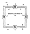
- FIG. 1 shows, in simplified form, bidirectional line-switched ring transmission system 100, which for brevity and clarity of exposition is shown as including only ring nodes 101 through 104, each incorporating an illustrative example of the invention.
- Ring nodes 101 through 104 are interconnected by transmission path 110 in a counterclockwise direction and by transmission path 120 in a clockwise direction.
- transmission paths 110 and 120 are comprised of optical fibers and each could be comprised of a single optical fiber or two (2) optical fibers. That is, bidirectional line-switched ring transmission system 100 could be either a two (2) optical fiber or a four (4) optical fiber system. In a two (2) optical fiber system, each of the fibers in transmission paths 110 and 120 includes service bandwidth and protection bandwidth.
- each of transmission paths 110 and 120 includes an optical fiber for service bandwidth and a separate optical fiber for protection bandwidth.
- Such bidirectional line-switched ring transmission systems are known.
- transmission of digital signals in the SONET digital signal format is assumed.
- the invention is equally applicable to other digital signal formats, for example. the CCITT synchronous digital hierarchy (SDH) digital signal formats.
- SDH CCITT synchronous digital hierarchy
- an optical OC-N SONET digital signal format is being utilized for transmission over transmission paths 110 and 120.
- the SONET digital signal formats are described in a Technical Advisory entitled "Synchronous Optical Network (SONET) Transport Systems: Common Generic Criteria", TA-NWT-000253, Bell Communications Research. Issue 6. September 1990.
- requests and acknowledgments for protection switch action are transmitted in an automatic protection switch ("APS") channel in the SONET overhead accompanying the protection bandwidth on each of transmission paths 110 and 120.
- the APS channel in the SONET format, comprises the K 1 and K2 bytes in the SONET overhead of the protection bandwidth.
- the K1 byte indicates a request of a communications circuit for switch action.
- the first four (4) bits of the K1 byte indicate the switch request priority and the last four (4) bits indicate the ring node identification (ID).
- the K2 byte indicates an acknowledgment of the requested protection switch action.
- the first four (4) bits of the K2 byte indicate the ring node ID and the last 4 bits indicate the action taken.
- a "communications circuit" is considered to be a SONET STS-3 digital signal having its entry and exit points on the ring.
- Each of ring nodes 101 through 104 comprises an add-drop multiplexer ("ADM").
- ADM add-drop multiplexer
- SONET ADM SONET ADD-DROP Multiplex Equipment
- GENERIC CRITERIA TR-TSY-000496, Issue 2. September 1989, Supplement 1, September 1991, Bell Communications Research.
- the ADM operates in a transmission sense to pass signals through the ring node, to add signals at the ring node, to drop signals at the ring node, to bridge signals during a protection switch and to loop-back-switch signals during a protection switch at the ring node.
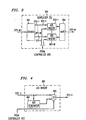
- FIG. 2 shows, in simplified block diagram form, details of ring nodes 101 through 104, including an embodiment of the invention.
- a west (W)-to-east (E) digital signal transmission direction is assumed in the service bandwidth and the protection bandwidth on transmission path 110.
- E east
- W west
- W west
- W west
- W east
- W west
- W west
- Receiver 201 includes an optical/electrical (O/E) interface 202 and a demultiplexer (DEMUX) 203, which yields at least one (1) STS-M SONET digital signal.
- O/E interfaces and demultiplexers are known.
- M is assumed to be three (3) and N is greater than M.
- the STS-M signal output from DEMUX 203 is supplied to squelcher (S) 204 which under control of controller 205 controllably squelches, i.e., blocks. particular incoming communications circuits by inserting an alarm indication signal (AIS), as described below. Details of squelcher (S) 204 are shown in FIGs. 3 and 4 and its operation is described below.
- AIS alarm indication signal
- the STS-M signal is supplied to broadcast element 206.
- a broadcast element replicates the STS-M signal supplied to it and supplies the replicated signals as a plurality of individual outputs. Such broadcast elements are known.
- Broadcast element 206 generates three identical STS-M signals and supplies one STS-M signal to an input of 3:1 selector 207, a second STS-M signal to an input of 2:1 selector 208 and a third STS-M signal to an input of 3:1 selector 209.
- An STS-M signal output from 3:1 selector 207 is supplied to squelcher (S) 210, which is identical to squelcher (S) 204.
- Squelcher (S) 210 is employed, under control of controller 205, to squelch particular outgoing communications circuits.
- the STS-M signal output from squelcher (S) 210 is supplied to transmitter 211 and, therein, to multiplexer (MUX) 212.
- the output of MUX 212 is an electrical OC-N digital signal, which is interfaced to transmission path 110 via electrical/optical (E/O) interface 213.
- E/O electrical/optical
- Such multiplexers (MUXs) and electrical/optical (E/O) interfaces are well known.
- an OC-N optical signal is supplied via transmission path 120 to receiver 214 and, therein, to optical/electrical (O/E) interface 215.
- demultiplexer (DEMUX) 216 yields a STS-M signal which is supplied via squelcher (S) 217 to broadcast element 218.
- Broadcast element 218 replicates the STS-M signal into a plurality of identical STS-M signals, in this example, three (3).
- One STS-M signal is supplied to an input of 3:1 selector 207, a second STS-M signal is supplied to an input of 2:1 selector 208 and a third STS-M signal is supplied to an input of 3:1 selector 209.
- An output from 3:1 selector 209 is supplied via squelcher (S) 219 to transmitter 220.
- multiplexer (MUX) 221 multiplexes the STS-M into an electrical OC-N and, then, electrical/optical (E/O) interface 222 supplies the optical OC-N signal to transmission path 120.
- Controller 205 operates to effect the deterministic squelching of communications circuits. Controller 205 communicates with receivers 201 and 214 and transmitters 211 and 220 via bus 223 and with interface 224 via bus 227. Specifically, in this illustrative example, controller 205 monitors the incoming digital signals to determine loss-of-signal, SONET format K bytes and the like. Additionally, controller 205 causes the insertion of appropriate K byte messages for protection switching purposes, examples of which are described below. To realize the desired deterministic squelching of the communications circuits, controller 205 may be advantageously provisioned via bus 228 with the identities ("IDs") of all the active communications circuits in the ring node. These include those communications circuits passing through the ring node. as well as.
- IDs identities
- the identities of all the ring nodes in bidirectional line-switched ring 100 may also be provisioned to controller 205. However. in-band signaling may also be used to supply ring nodes 101 through 104 with the identities of all the ring nodes in bidirectional line-switched ring 100 and the identities of communications circuits active in the ring node. In this scheme, control signals are embedded in the data stream itself. Alternatively. such identification could also be made using a central controller at some remote location to the ring, and the results forwarded to each ring node 101 through 104. The squelching of communications circuits under control of controller 205 to effect the invention is described below.
- Interface 224 is employed to interface to a particular duplex link 225 and could include any desired arrangement.
- interface 224 could include a DS3 digital signal interface to a DSX, a STS-1E (electrical) SONET digital signal interfacing to a DSX, an optical extension interface to an OC-N SONET optical signal or the like.
- Such interface arrangements are known.
- a signal (R) to be dropped at the ring node is supplied to interface 224 via 2:1 selector 208, under control of controller 205, from either broadcast element 206 or broadcast element 218.
- interface 224 supplies the appropriate signal to duplex link 225.
- a signal (T) to be added at the ring node is supplied from duplex link 225 to interface 224 where it is converted to the STS-M digital signal format, if necessary.
- the STS-M digital signal is then supplied to broadcast element 226 where it is replicated.
- the replicated STS-M digital signals are supplied by broadcast element 226 to an input of 3:1 selector 207 and an input of 3:1 selector 209. In this example, 3: 1 selectors 207 and 209, under control of controller 205, select the signal being added for transmission in the service bandwidth or the protection bandwidth on either transmission path 110 or transmission path 120.
- the normal transmission path for a digital signal being added at the ring node would be in the service bandwidth on transmission path 110 and transmission path 120. for example, towards the west (W).
- the signal (T) being added from interface 224 would be bridged via broadcast element 226 and chosen by 3: 1 selector 207, under control of controller 205. to the protection bandwidth on transmission path 110.
- the signal (R) to be dropped at the ring node would be received in the protection bandwidth on transmission path 120 and would be switched from broadcast element 218 via 2: 1 selector 208 to interface 224.
- a node isolation failure is a failure where a group of one or more ring nodes appear to be failed since they are unreachable by other ring nodes in the ring transmission system because of other failed ring nodes or by fiber and/or cable cuts. If the transmission path for the signal (R) is the protection bandwidth, the signal (R) to be dropped would be switched in a ring node adjacent the failure from the protection bandwidth on transmission path 120 to the service bandwidth on transmission path 110 and received at the ring node in the usual fashion. Then, the signal (R) being dropped from transmission path 110 is supplied via broadcast element 206 and 2:1 selector 208 to interface 224.
- controller 205 monitors the status of interface 224 and the digital signal supplied thereto via bus 227. Specifically, controller 205 monitors interface 224 for loss-of-signal, coding violations and the like, i.e., a signal failure condition. Under control of controller 205, digital signals may be passed through, added at, dropped at, bridged at or loop-back-switched at the ring node. A loop-back-switch of an STS-M digital signal incoming in the service bandwidth on transmission path 110 is effected by . controller 205 causing 3:1 selector 209 to select the STS-M digital signal from broadcast element 206 and supplying it via squelcher (S) 219 to transmitter 220.
- S squelcher
- transmitter 220 supplies an OC-N optical signal to the protection bandwidth on transmission path 120. It will be apparent that in the loop-back-switch operation, if the signal is incoming in a service bandwidth on transmission path 110, it will be loop-back-switched to the protection bandwidth on transmission path 120 and vice versa. If the signal is incoming in protection bandwidth on transmission path 110, it will be loop-back-switched to the service bandwidth on transmission path 120 and vice versa.
- a signal to be added at the ring node is supplied from interface 224, replicated via broadcast element 226 and selected either by 3:1 selector 207 or 3: 1 selector 209, under control of controller 205, to be added on transmission path 110 or transmission path 120, respectively.
- a digital signal to be dropped at the ring node is selected by 2:1 selector 208, under control of controller 205, either from broadcast element 206 (transmission path 110) or broadcast element 218 (transmission path 120).
- the pass-through and loop-back-switch functions for a signal incoming on transmission path 120 is identical to that for an incoming signal on transmission path 110.
- bidirectional line-switched ring 100 Possible communications circuit misconnections are avoided in bidirectional line-switched ring 100 by deterministically squelching particular communications circuits active in a particular ring node using a generalized deterministic squelching method which is described in detail below.
- each ring node in bidirectional line-switched ring transmission system 100 is typically equipped to effect the desired squelching via squelchers (S) 204, 210, 217 and 219, under control of controller 205.
- S squelchers
- both incoming and outgoing communications circuits are squelched, however. it may only be necessary to squelch outgoing communications circuits.
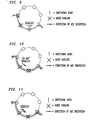
- FIG. 3 shows, in simplified block diagram form, details of an exemplary squelcher (S) unit.
- the STS-M digital signal is supplied to demultiplexer (DEMUX) 301 where it is demultiplexed into its constituent M STS-1 digital signals 302-1 through 302-M.
- the M STS-1 digital signals are supplied on a one-to-one basis to AIS insert units 303-1 through 303-M.
- AIS insert units 303-1 through 303-M under control of controller 205, insert the AIS in the STS-1 digital signals included in the communications circuits, i.e., STS-M digital signals, to be squelched. Details of AIS insert units 303 are shown in FIG. 4 and described below.
- the M STS-1 digital signals are multiplexed in multiplexer (MUX) 304 to yield the desired STS-M digital signal.
- MUX multiplexer
- FIG. 4 shows, in simplified block diagram form, details of AIS insert units 303. Specifically. shown is a STS-1 digital signal being supplied to AIS generator 401 and to one input of 2:1 selector 402. AIS generator 401 operates to insert AIS in the STS-1 digital signal. As indicated in the technical advisory TA-NWT-000253, the STS path AIS is an all ones (l's) signal in the STS-1 overhead bytes H1, H2 and H3 and the bytes of the entire STS SPE (synchronous payload envelope). Selector 402 selects as an output, under control of controller 205, either the incoming STS-1 digital signal or the STS-1 digital signal with AIS inserted from AIS generator 401.
- Deterministic squelching is provided by a method where, despite ring node failures, a communications circuit is delivered to as many drops as possible so long as there is at least one source that has not failed. It will be shown below that a generalized squelching method can be derived from two rules that have been developed for basic unidirectional circuits. For both rules, it is assumed that the particular ring node of interest (i.e., that ring node used as the loop back switching ring node to heal the ring), is adjacent to a failed ring node. These rules are:
- FIG. 5 is a flow chart illustrating the operation of controller 205 in controlling the ring nodes in order to effect the deterministic squelching of communications circuits in the presence of ring node failures, in accordance with the rules discussed above.
- the process is entered via step 501.
- operational block 502 causes the K bytes of an incoming OC-N signal to be observed and processes the ring node IDs therein.
- conditional branch point 503 tests to determine if the processed ring node IDs indicate that one or more ring nodes have failed.
- a ring node failure is defined as to include ring node equipment failure and node isolation failure caused by fiber cuts and the like. Specific examples of failure conditions are discussed below.
- the process is ended via step 514. If the processed ring node IDs indicate one or more ring node failures, operational block 506 causes the failed ring node IDs to be identified. Then, control is passed to operational block 507 which allows the identification of communications circuits potentially affected by the one or more failure. A communications circuit is potentially affected by the failure if it has an entry and/or exit (i.e., an "A" and/or "Z" termination) in the one or more failed ring nodes.
- conditional branching point 508 If the ring node failure scenario does not include a ring node adjacent to the switching ring node, then no squelching is performed, and the usual bridging and switching may occur as appropriate in operational block 513. If the failure scenario includes an adjacent ring node, then control is passed to conditional branching point 509. If the failed adjacent ring node is upstream from the switching ring node then control is passed to operational block 510.
- control is passed to operational block 512 where the communications circuit is squelched. If the furthest upstream entry ring node has not failed then control is passed to conditional branching point 511. Referring back to conditional branching point 509, if the failed adjacent ring node is downstream from the switching ring node, then control is passed to conditional branching point 511. If an exit ring node for a communications circuit which furthest downstream from the switching ring.node has failed. then control is passed to operational block 512 where the communications circuit is squelched.
- the steps of identifying failed ring nodes and identifying affected active communications circuits may be performed, for example, by using a ring "maps," or look-up tables, which are stored in each ring node in the system, in combination with line-switch request messages generated by the ring nodes.
- the ring maps could include, for example, information regarding the order in which ring nodes appear on the ring and ring node addresses at which each communications circuit enters and exits the ring.
- a given communications circuit may have multiple sources and multiple drops which implies multiple entry and exit ring node addresses.
- STS time slot information may also be included in the maps where appropriate.
- One example of the use of ring maps and line-switch request messages to identify failed ring nodes follows. Suppose a segment of a ring consisting of three ring nodes A. B. and C is observed. where B has failed. In a typical scenario, both A and C will send line-switch request messages in the APS channel K1 byte destined for B. When A sees the request from C, fails to receive a signal from B (i.e., A detects a loss-of-signal).
- a and C will then use their respective ring maps, and apply rules 1) and 2) above, to determine which communications circuits are affected by the failure of B, and squelch those affected circuits by inserting AIS, as described above, to thereby avoid misconnections.
- rules 1) and 2) are not applied to determine whether a particular communications circuit is affected by the ring node failures.
- communications circuits are simply squelched if they have a termination in a failed adjacent ring node.
- the described signaling is readily applicable to the present invention as an example of how the identification step in operational block 506 in FIG. 5 may be performed.
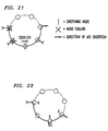
- FIGs. 6-22 illustrate examples of the operations of the generalized squelching rules discussed above.
- FIGs. 6-9 show a unidirectional circuit having a single entry ring node and a single exit ring node.
- the downstream ring node adjacent to the switching ring node has failed.
- no squelching is performed because, in accordance with rule 1) above, the single exit ring node, which by definition is the exit ring node furthest downstream from the switching ring node, has not failed.
- squelching is performed because the exit ring node has failed.
- FIGs. 8 and 9 the upstream ring node adjacent to the switching ring node has failed.
- no squelching is performed because.
- the single entry ring node which by definition is the entry ring node furthest upstream from the switching node, has not failed.
- squelching is performed because the entry ring node has failed.
- the combination of rules 1) and 2) give the known method for squelching simple bidirectional communications circuits, which is illustrated in FIGs. 10 and 11.
- FIG. 12 shows a multiply dropped unidirectional circuit.
- the generalized squelching method provides for delivery to as many drops as possible despite ring node failures.
- FIGs. 13 and 14 the downstream ring node adjacent to the switching ring node has failed.
- no squelching is performed because. in accordance with rule 1) above, the exit ring node furthest downstream from the switching ring node has not failed.
- FIG. 14 squelching is performed because the exit ring node furthest downstream from the switching ring node has failed.
- FIGs. 15 and 16 show that the upstream ring node adjacent to the switching ring node has failed. In FIG.
- FIG. 17 shows a multiply sourced unidirectional circuit.
- the intent of the squelching method is to deliver the communications circuit so long as there is at least one source that has not failed.
- FIGs. 18 and 19 the downstream ring node adjacent to the switching ring node has failed.
- squelching is not performed because, in accordance with rule 1) above, the exit ring node furthest downstream from the switching ring node has not failed.
- squelching is performed because the exit ring node furthest downstream from the switching ring node has failed.
- FIGs. 20 and 21 show that the upstream ring node adjacent to the switching ring node has failed.
- FIG. 20 and 21 show that the upstream ring node adjacent to the switching ring node has failed.
- no squelching is performed because, in accordance with rule 2) above, the entry ring node furthest upstream from the switching ring node has not failed.
- squelching is performed because the entry ring node furthest upstream from the switching ring node has failed.
- FIG. 22 shows another example of the generalized squelching method
- FIG. 22 shows two simple unidirectional circuits. Assume that both use the same tributary timeslot. Using rules 1) and 2) above, if ring node B fails, both circuits are squelched. Now suppose that FIG. 22 represents a variation of ring interworking where two unidirectional circuits occupy the same timeslot. Suppose, therefore, that it is desirable to permit a secondary connection during the failure of ring node B (as is the case in ring interworking). Now squelching is only dependent on A and C and not B. If ring node B fails. the circuits are not squelched and a secondary connection is permitted from A to C. It is evident from the two examples illustrated by FIG. 22 that the service intent is needed in order to determine how to squelch. Merely knowing the entry and exit ring nodes is not sufficient in special cases such as these.
Claims (11)
- Procédé destiné à être utilisé avec un noeud d'anneau prédéterminé (104) d'une pluralité de noeuds d'anneau (101 à 104) dans un système de transmission en anneau (100), ledit système de transmission en anneau transportant des circuits de communications ayant au moins un noeud d'anneau d'entrée (103) et au moins un noeud d'anneau de sortie (101), ledit noeud d'anneau prédéterminé comportant un moyen de contrôleur (205) adapté pour recevoir les identités de tous les circuits de communications actifs dans le noeud d'anneau prédéterminé, et un moyen (205) adapté pour mémoriser des identités de noeuds d'anneau dans le système de transmission en anneau, le procédé comportant les étapes de :dans lequel d'éventuelles mauvaises connexions des circuits de communications sont évitées.a) détection et identification (205, 502, 503, 506) de noeuds d'anneau défectueux dans ledit système de transmission en anneau y compris des positions desdits noeuds d'anneau défectueux dans ledit système de transmission en anneau par rapport audit noeud d'anneau prédéterminé en surveillant (205) les signaux entrant dans ledit noeud d'anneau prédéterminé, ladite surveillance comportant la détection (205) d'une condition de défaillance de signal, y compris la détection d'au moins un message de demande de commutation, arrivant audit noeud d'anneau prédéterminé sur l'un ou l'autre d'un premier (110) ou d'un deuxième (120) trajet de transmission, ledit premier trajet de transmission (110) couplant ladite pluralité de noeuds d'anneau et transportant des circuits de communications autour dudit système de transmission en anneau dans un premier sens, et ledit deuxième trajet de transmission (120) couplant ladite pluralité de noeuds d'anneau et transportant des circuits de communications autour dudit système de transmission en anneau dans un deuxième sens opposé audit premier sens ; etb) détection et identification de circuits de communications actifs dans ledit noeud d'anneau prédéterminé ;
le procédé étant CARACTÉRISÉ PARc) le blocage automatique (205, 204, 210, 217, 219 512) d'un circuit de communications actif dans ledit noeud d'anneau prédéterminé en réponse auxdites identifications dans les étapes a) et b) si
un premier noeud d'anneau (101 ou 103, 508, 509) qui est en aval dudit noeud d'anneau prédéterminé, et adjacent à celui-ci, sur l'un ou l'autre dudit premier ou dudit deuxième trajet de transmission est défectueux, et
un noeud d'anneau de sortie (101, 102 ou 103, 509, 511) d'un ou de plusieurs noeuds d'anneau de sortie dudit circuit de communications actif devant être bloqué automatiquement, qui est le plus en aval dudit noeud d'anneau prédéterminé est défectueux ; etd) si aucun blocage automatique n'est effectué sur ledit circuit de communications actif conformément à l'étape c), alors le blocage automatique (205, 204, 210, 217, 219, 512) dudit circuit de communications actif dans ledit noeud d'anneau prédéterminé si un deuxième noeud d'anneau (508, 509) qui est en amont dudit noeud d'anneau prédéterminé, et adjacent à celui-ci, est défectueux, et
un noeud d'entrée (510) d'un ou de plusieurs noeuds d'anneau d'entrée pour ledit circuit de communications actif devant être bloqué automatiquement qui est le plus en amont dudit noeud d'anneau prédéterminé est défectueux, - Procédé selon la revendication 1, dans lequel ladite étape de détection et d'identification de noeuds d'anneau défectueux est sensible auxdites identités mémorisées de noeuds d'anneau dans ledit système de transmission et audit au moins un message de demande de commutation détecté afin d'identifier des noeuds d'anneau défectueux à partir desdites identités mémorisées (205).
- Procédé selon la revendication 2, dans lequel ledit au moins un message de demande de commutation est transporté (205, 212, 221) dans un canal de commutation de protection automatique dans ladite largeur de bande de protection des deux dits premier et deuxième trajets de transmission.
- Procédé selon la revendication 1, dans lequel lesdites étapes de blocage automatique (205, 204, 512) comportent le blocage de la transmission dudit circuit de communications devant être bloqué automatiquement.
- Procédé selon la revendication 1, dans lequel lesdites étapes de blocage automatique comportent la génération d'un signal d'indication d'alarme et l'insertion dudit signal d'indication d'alarme (205, 204, 303) dans des positions d'octets prescrites dans lesdits circuits de communications devant être bloqués automatiquement.
- Procédé destiné à être utilisé dans le blocage automatique déterministe de circuits de communications (205, 204, 210, 217, 219, 512) dans un système de transmission en anneau (100) comportant une pluralité de noeuds d'anneau (102 à 104), le procédé étant un procédé tel que revendiqué à la revendication 1, dans lequel les étapes a) à d) sont appliquées à au moins l'un (104) de ladite pluralité de noeuds d'anneau (101 à 104 ) .
- Noeud d'anneau (104), ledit noeud d'anneau étant un noeud d'anneau prédéterminé d'une pluralité de noeuds d'anneau (101 à 104) dans un système de transmission en anneau (100), ledit système de transmission en anneau étant adapté pour transporter des circuits de communications ayant au moins un noeud d'anneau d'entrée et au moins un noeud d'anneau de sortie, ledit noeud d'anneau prédéterminé comportant un moyen de contrôleur (205) adapté pour recevoir les identités de tous les circuits de communications actifs dans le noeud d'anneau prédéterminé, et un moyen (205) adapté pour mémoriser des identités de noeuds d'anneau dans le système de transmission en anneau, le noeud d'anneau prédéterminé comportant :dans lequel d'éventuelles mauvaises connexions des circuits de communications sont évitées.a) des moyens (205, 502, 503, 506) adaptés pour détecter et identifier des noeuds d'anneau défectueux dans ledit système de transmission en anneau y compris des positions desdits noeuds d'anneau défectueux, lesdits moyens adaptés pour détecter et identifier comportant un moyen (205) adapté pour surveiller les signaux entrant dans ledit noeud d'anneau prédéterminé, ledit moyen adapté pour surveiller comportant un moyen (205) adapté pour détecter une condition de défaillance de signal, y compris un moyen adapté pour détecter au moins un message de demande de commutation, arrivant audit noeud d'anneau prédéterminé sur l'un ou l'autre d'un premier (110) ou d'un deuxième (120) trajet de transmission, ledit premier trajet de transmission (110) étant adapté pour coupler ladite pluralité de noeuds d'anneau et transporter des circuits de communications autour dudit système de transmission en anneau dans un premier sens, et ledit deuxième trajet de transmission (120) étant adapté pour coupler ladite pluralité de noeuds d'anneau et transporter des circuits de communications autour dudit système de transmission en anneau dans un deuxième sens opposé audit premier sens ; etb) un moyen (205) adapté pour détecter et identifier des circuits de communications actifs dans ledit noeud d'anneau prédéterminé ;
ledit noeud d'anneau prédéterminé étant CARACTÉRISÉ PARc) au moins un moyen (205, 204, 210, 217, 219, 512) adapté pour bloquer automatiquement un circuit de communications actif dans ledit noeud d'anneau prédéterminé en réponse auxdites identifications dans a) et b) si
un premier noeud d'anneau (p. ex. 101 ou 103, 508, 509) qui est en aval dudit noeud d'anneau prédéterminé, et adjacent à celui-ci, sur l'un ou l'autre dudit premier ou dudit deuxième trajet de transmission est défectueux, et
un noeud d'anneau de sortie (101, 102 ou 103, 509, 511) des un ou plusieurs noeuds d'anneau de sortie dudit circuit de communications actif devant être bloqué automatiquement, qui est le plus en aval dudit noeud d'anneau prédéterminé est défectueux ; etd) un moyen adapté pour, si aucun blocage automatique n'est effectué sur ledit circuit de communications actif conformément à l'étape c), bloquer automatiquement (205, 204, 210, 217, 219, 512) ledit circuit de communications actif dans ledit noeud d'anneau prédéterminé si
un deuxième noeud d'anneau qui est en amont dudit noeud d'anneau prédéterminé, et adjacent à celui-ci, est défectueux (508, 509), et
un noeud d'anneau d'entrée (510) d'un ou de plusieurs noeuds d'anneau d'entrée pour ledit circuit de communications actif devant être bloqué automatiquement , qui est le plus en amont dudit noeud d'anneau prédéterminé est défectueux, - Noeud d'anneau selon la revendication 7, dans lequel ledit moyen adapté pour détecter et identifier des noeuds d'anneau défectueux est sensible auxdites identités mémorisées de noeuds d'anneau dans ledit système de transmission et audit au moins un message de demande de commutation détecté afin d'identifier des noeuds d'anneau défectueux à partir desdites identités mémorisées (205).
- Noeud d'anneau selon la revendication 8, comportant un moyen adapté pour fournir ledit au moins un message de demande de commutation à transporter (205, 212, 221) dans un canal de commutation de protection automatique dans ladite largeur de bande de protection des deux dits premier et deuxième trajets de transmission.
- Noeud d'anneau selon la revendication 7, dans lequel ledit au moins un moyen adapté pour bloquer automatiquement est adapté pour bloquer (205, 204, 512) la transmission dudit circuit de communications devant être bloqué automatiquement.
- Noeud d'anneau selon la revendication 7, dans lequel ledit au moins un moyen adapté pour bloquer automatiquement (205, 204, 303) est adapté pour générer un signal d'indication d'alarme et pour insérer ledit signal d'indication d'alarme dans des positions d'octets prescrites dans ledit circuit de communication devant être bloqué automatiquement.
Applications Claiming Priority (2)
| Application Number | Priority Date | Filing Date | Title |
|---|---|---|---|
| US32572794A | 1994-10-19 | 1994-10-19 | |
| US325727 | 2001-09-28 |
Publications (3)
| Publication Number | Publication Date |
|---|---|
| EP0708542A2 EP0708542A2 (fr) | 1996-04-24 |
| EP0708542A3 EP0708542A3 (fr) | 1999-01-13 |
| EP0708542B1 true EP0708542B1 (fr) | 2003-12-17 |
Family
ID=23269173
Family Applications (1)
| Application Number | Title | Priority Date | Filing Date |
|---|---|---|---|
| EP95307185A Expired - Lifetime EP0708542B1 (fr) | 1994-10-19 | 1995-10-11 | Circuit de silencieux généralisé et déterministe pour un système de transmission en forme d'anneau |
Country Status (5)
| Country | Link |
|---|---|
| EP (1) | EP0708542B1 (fr) |
| JP (1) | JP3226773B2 (fr) |
| KR (1) | KR100298968B1 (fr) |
| CA (1) | CA2160392C (fr) |
| DE (1) | DE69532317T2 (fr) |
Families Citing this family (4)
| Publication number | Priority date | Publication date | Assignee | Title |
|---|---|---|---|---|
| JP3259126B2 (ja) | 1995-09-26 | 2002-02-25 | 富士通株式会社 | リング伝送システム及び該システムのスケルチ方法 |
| JP3754416B2 (ja) * | 2000-07-17 | 2006-03-15 | 株式会社東芝 | トラフィックの自己救済方式およびリエスタブリッシュ方式 |
| KR100703293B1 (ko) * | 2001-02-28 | 2007-04-03 | 삼성전자주식회사 | 관리 채널 모니터링을 이용한 인접 노드 이상 경보 방법 |
| IL151796A0 (en) | 2002-09-18 | 2003-04-10 | Lightscape Networks Ltd | Method for protection of ethernet traffic in optical ring networks |
Family Cites Families (6)
| Publication number | Priority date | Publication date | Assignee | Title |
|---|---|---|---|---|
| US5159595A (en) * | 1988-04-08 | 1992-10-27 | Northern Telecom Limited | Ring transmission system |
| US5442620A (en) * | 1992-03-26 | 1995-08-15 | At&T Corp. | Apparatus and method for preventing communications circuit misconnections in a bidirectional line-switched ring transmission system |
| US5278824A (en) * | 1992-06-02 | 1994-01-11 | At&T Bell Laboratories | Dual hubbing in a bidirectional line-switched ring transmission system |
| US5406401A (en) * | 1992-10-02 | 1995-04-11 | At&T Corp. | Apparatus and method for selective tributary switching in a bidirectional ring transmission system |
| JP3354622B2 (ja) * | 1993-03-29 | 2002-12-09 | 富士通株式会社 | 双方向伝送路切替リングネットワーク |
| JP3301565B2 (ja) * | 1993-08-23 | 2002-07-15 | 日本電信電話株式会社 | リング伝送装置 |
-
1995
- 1995-10-11 EP EP95307185A patent/EP0708542B1/fr not_active Expired - Lifetime
- 1995-10-11 DE DE69532317T patent/DE69532317T2/de not_active Expired - Fee Related
- 1995-10-12 CA CA002160392A patent/CA2160392C/fr not_active Expired - Fee Related
- 1995-10-18 JP JP29383695A patent/JP3226773B2/ja not_active Expired - Fee Related
- 1995-10-19 KR KR1019950036099A patent/KR100298968B1/ko not_active IP Right Cessation
Also Published As
| Publication number | Publication date |
|---|---|
| KR960016245A (ko) | 1996-05-22 |
| EP0708542A2 (fr) | 1996-04-24 |
| CA2160392A1 (fr) | 1996-04-20 |
| DE69532317T2 (de) | 2004-10-21 |
| KR100298968B1 (ko) | 2001-10-22 |
| JP3226773B2 (ja) | 2001-11-05 |
| DE69532317D1 (de) | 2004-01-29 |
| CA2160392C (fr) | 1999-09-21 |
| JPH08214020A (ja) | 1996-08-20 |
| EP0708542A3 (fr) | 1999-01-13 |
Similar Documents
| Publication | Publication Date | Title |
|---|---|---|
| US5406401A (en) | Apparatus and method for selective tributary switching in a bidirectional ring transmission system | |
| US5442620A (en) | Apparatus and method for preventing communications circuit misconnections in a bidirectional line-switched ring transmission system | |
| EP0573217B1 (fr) | Liaison duale dans un système bidirectionnel, un anneau avec des lignes commutées | |
| US5440540A (en) | Ring interworking between a bidirectional line-switched ring transmission system and another ring transmission system | |
| EP0654924B1 (fr) | Système de communication ayant des systèmes de transmission interconnectés, bidirectionelles et annulaires avec des lignes commutées | |
| US5394389A (en) | Ring interworking between bidirectional line-switched ring transmission systems and path-switched ring transmission systems | |
| JP3195465B2 (ja) | 双方向多重区間切替式リング伝送システムおよび通信信号転送方法 | |
| US6009075A (en) | Transport interface for performing protection switching of telecommunications traffic | |
| US5818816A (en) | Communication device for switching connection from a working channel line to a protection channel line and vice versa | |
| EP0654923B1 (fr) | Système de communication ayant des systèmes de transmission interconnectés et annulaires avec des chemins commutés | |
| EP0984574B1 (fr) | Restoration d'erreur rétro-compatible dans des système de transmission en anneaux avec des sections de commutation bidirectionnelles multiplexées | |
| US6807190B1 (en) | Survivable distribution of broadcast signals in loopback rings | |
| EP0708542B1 (fr) | Circuit de silencieux généralisé et déterministe pour un système de transmission en forme d'anneau | |
| US20020067700A1 (en) | Office recognition method in ring network | |
| US20010050789A1 (en) | Method for controlling signal path in optical transmission system |
Legal Events
| Date | Code | Title | Description |
|---|---|---|---|
| PUAI | Public reference made under article 153(3) epc to a published international application that has entered the european phase |
Free format text: ORIGINAL CODE: 0009012 |
|
| AK | Designated contracting states |
Kind code of ref document: A2 Designated state(s): DE FR GB IT NL SE |
|
| PUAL | Search report despatched |
Free format text: ORIGINAL CODE: 0009013 |
|
| AK | Designated contracting states |
Kind code of ref document: A3 Designated state(s): DE FR GB IT NL SE |
|
| 17P | Request for examination filed |
Effective date: 19990705 |
|
| 17Q | First examination report despatched |
Effective date: 20021107 |
|
| GRAH | Despatch of communication of intention to grant a patent |
Free format text: ORIGINAL CODE: EPIDOS IGRA |
|
| GRAS | Grant fee paid |
Free format text: ORIGINAL CODE: EPIDOSNIGR3 |
|
| GRAA | (expected) grant |
Free format text: ORIGINAL CODE: 0009210 |
|
| AK | Designated contracting states |
Kind code of ref document: B1 Designated state(s): DE FR GB IT NL SE |
|
| REG | Reference to a national code |
Ref country code: GB Ref legal event code: FG4D |
|
| REF | Corresponds to: |
Ref document number: 69532317 Country of ref document: DE Date of ref document: 20040129 Kind code of ref document: P |
|
| REG | Reference to a national code |
Ref country code: SE Ref legal event code: TRGR |
|
| ET | Fr: translation filed | ||
| PLBE | No opposition filed within time limit |
Free format text: ORIGINAL CODE: 0009261 |
|
| STAA | Information on the status of an ep patent application or granted ep patent |
Free format text: STATUS: NO OPPOSITION FILED WITHIN TIME LIMIT |
|
| 26N | No opposition filed |
Effective date: 20040920 |
|
| PGFP | Annual fee paid to national office [announced via postgrant information from national office to epo] |
Ref country code: NL Payment date: 20081015 Year of fee payment: 14 |
|
| PGFP | Annual fee paid to national office [announced via postgrant information from national office to epo] |
Ref country code: DE Payment date: 20081022 Year of fee payment: 14 |
|
| PGFP | Annual fee paid to national office [announced via postgrant information from national office to epo] |
Ref country code: SE Payment date: 20081014 Year of fee payment: 14 Ref country code: IT Payment date: 20081025 Year of fee payment: 14 |
|
| PGFP | Annual fee paid to national office [announced via postgrant information from national office to epo] |
Ref country code: FR Payment date: 20081014 Year of fee payment: 14 |
|
| PGFP | Annual fee paid to national office [announced via postgrant information from national office to epo] |
Ref country code: GB Payment date: 20081021 Year of fee payment: 14 |
|
| REG | Reference to a national code |
Ref country code: NL Ref legal event code: V1 Effective date: 20100501 |
|
| EUG | Se: european patent has lapsed | ||
| REG | Reference to a national code |
Ref country code: FR Ref legal event code: ST Effective date: 20100630 |
|
| PG25 | Lapsed in a contracting state [announced via postgrant information from national office to epo] |
Ref country code: NL Free format text: LAPSE BECAUSE OF NON-PAYMENT OF DUE FEES Effective date: 20100501 Ref country code: FR Free format text: LAPSE BECAUSE OF NON-PAYMENT OF DUE FEES Effective date: 20091102 Ref country code: DE Free format text: LAPSE BECAUSE OF NON-PAYMENT OF DUE FEES Effective date: 20100501 |
|
| PG25 | Lapsed in a contracting state [announced via postgrant information from national office to epo] |
Ref country code: GB Free format text: LAPSE BECAUSE OF NON-PAYMENT OF DUE FEES Effective date: 20091011 |
|
| PG25 | Lapsed in a contracting state [announced via postgrant information from national office to epo] |
Ref country code: IT Free format text: LAPSE BECAUSE OF NON-PAYMENT OF DUE FEES Effective date: 20091011 |
|
| PG25 | Lapsed in a contracting state [announced via postgrant information from national office to epo] |
Ref country code: SE Free format text: LAPSE BECAUSE OF NON-PAYMENT OF DUE FEES Effective date: 20091012 |