EP0708431A2 - Dispositif de projection utilisant un dispositif d'affichage à effet de champ - Google Patents
Dispositif de projection utilisant un dispositif d'affichage à effet de champ Download PDFInfo
- Publication number
- EP0708431A2 EP0708431A2 EP95307437A EP95307437A EP0708431A2 EP 0708431 A2 EP0708431 A2 EP 0708431A2 EP 95307437 A EP95307437 A EP 95307437A EP 95307437 A EP95307437 A EP 95307437A EP 0708431 A2 EP0708431 A2 EP 0708431A2
- Authority
- EP
- European Patent Office
- Prior art keywords
- image
- field emission
- emission device
- fed
- projecting
- Prior art date
- Legal status (The legal status is an assumption and is not a legal conclusion. Google has not performed a legal analysis and makes no representation as to the accuracy of the status listed.)
- Withdrawn
Links
Images

Classifications
-
- H—ELECTRICITY
- H04—ELECTRIC COMMUNICATION TECHNIQUE
- H04N—PICTORIAL COMMUNICATION, e.g. TELEVISION
- H04N5/00—Details of television systems
- H04N5/74—Projection arrangements for image reproduction, e.g. using eidophor
-
- H—ELECTRICITY
- H04—ELECTRIC COMMUNICATION TECHNIQUE
- H04N—PICTORIAL COMMUNICATION, e.g. TELEVISION
- H04N9/00—Details of colour television systems
- H04N9/12—Picture reproducers
- H04N9/31—Projection devices for colour picture display, e.g. using electronic spatial light modulators [ESLM]
-
- G—PHYSICS
- G03—PHOTOGRAPHY; CINEMATOGRAPHY; ANALOGOUS TECHNIQUES USING WAVES OTHER THAN OPTICAL WAVES; ELECTROGRAPHY; HOLOGRAPHY
- G03B—APPARATUS OR ARRANGEMENTS FOR TAKING PHOTOGRAPHS OR FOR PROJECTING OR VIEWING THEM; APPARATUS OR ARRANGEMENTS EMPLOYING ANALOGOUS TECHNIQUES USING WAVES OTHER THAN OPTICAL WAVES; ACCESSORIES THEREFOR
- G03B21/00—Projectors or projection-type viewers; Accessories therefor
- G03B21/132—Overhead projectors, i.e. capable of projecting hand-writing or drawing during action
-
- G—PHYSICS
- G09—EDUCATION; CRYPTOGRAPHY; DISPLAY; ADVERTISING; SEALS
- G09G—ARRANGEMENTS OR CIRCUITS FOR CONTROL OF INDICATING DEVICES USING STATIC MEANS TO PRESENT VARIABLE INFORMATION
- G09G3/00—Control arrangements or circuits, of interest only in connection with visual indicators other than cathode-ray tubes
- G09G3/20—Control arrangements or circuits, of interest only in connection with visual indicators other than cathode-ray tubes for presentation of an assembly of a number of characters, e.g. a page, by composing the assembly by combination of individual elements arranged in a matrix no fixed position being assigned to or needed to be assigned to the individual characters or partial characters
- G09G3/22—Control arrangements or circuits, of interest only in connection with visual indicators other than cathode-ray tubes for presentation of an assembly of a number of characters, e.g. a page, by composing the assembly by combination of individual elements arranged in a matrix no fixed position being assigned to or needed to be assigned to the individual characters or partial characters using controlled light sources
-
- H—ELECTRICITY
- H04—ELECTRIC COMMUNICATION TECHNIQUE
- H04N—PICTORIAL COMMUNICATION, e.g. TELEVISION
- H04N13/00—Stereoscopic video systems; Multi-view video systems; Details thereof
- H04N13/30—Image reproducers
- H04N13/324—Colour aspects
-
- H—ELECTRICITY
- H04—ELECTRIC COMMUNICATION TECHNIQUE
- H04N—PICTORIAL COMMUNICATION, e.g. TELEVISION
- H04N13/00—Stereoscopic video systems; Multi-view video systems; Details thereof
- H04N13/30—Image reproducers
- H04N13/332—Displays for viewing with the aid of special glasses or head-mounted displays [HMD]
- H04N13/337—Displays for viewing with the aid of special glasses or head-mounted displays [HMD] using polarisation multiplexing
-
- H—ELECTRICITY
- H04—ELECTRIC COMMUNICATION TECHNIQUE
- H04N—PICTORIAL COMMUNICATION, e.g. TELEVISION
- H04N13/00—Stereoscopic video systems; Multi-view video systems; Details thereof
- H04N13/30—Image reproducers
- H04N13/363—Image reproducers using image projection screens
-
- G—PHYSICS
- G09—EDUCATION; CRYPTOGRAPHY; DISPLAY; ADVERTISING; SEALS
- G09G—ARRANGEMENTS OR CIRCUITS FOR CONTROL OF INDICATING DEVICES USING STATIC MEANS TO PRESENT VARIABLE INFORMATION
- G09G2310/00—Command of the display device
- G09G2310/02—Addressing, scanning or driving the display screen or processing steps related thereto
- G09G2310/0235—Field-sequential colour display
-
- G—PHYSICS
- G09—EDUCATION; CRYPTOGRAPHY; DISPLAY; ADVERTISING; SEALS
- G09G—ARRANGEMENTS OR CIRCUITS FOR CONTROL OF INDICATING DEVICES USING STATIC MEANS TO PRESENT VARIABLE INFORMATION
- G09G3/00—Control arrangements or circuits, of interest only in connection with visual indicators other than cathode-ray tubes
- G09G3/001—Control arrangements or circuits, of interest only in connection with visual indicators other than cathode-ray tubes using specific devices not provided for in groups G09G3/02 - G09G3/36, e.g. using an intermediate record carrier such as a film slide; Projection systems; Display of non-alphanumerical information, solely or in combination with alphanumerical information, e.g. digital display on projected diapositive as background
-
- H—ELECTRICITY
- H01—ELECTRIC ELEMENTS
- H01J—ELECTRIC DISCHARGE TUBES OR DISCHARGE LAMPS
- H01J2329/00—Electron emission display panels, e.g. field emission display panels
-
- H—ELECTRICITY
- H04—ELECTRIC COMMUNICATION TECHNIQUE
- H04N—PICTORIAL COMMUNICATION, e.g. TELEVISION
- H04N5/00—Details of television systems
- H04N5/66—Transforming electric information into light information
- H04N5/70—Circuit details for electroluminescent devices
-
- H—ELECTRICITY
- H04—ELECTRIC COMMUNICATION TECHNIQUE
- H04N—PICTORIAL COMMUNICATION, e.g. TELEVISION
- H04N9/00—Details of colour television systems
- H04N9/12—Picture reproducers
- H04N9/30—Picture reproducers using solid-state colour display devices
Definitions
- the present invention relates generally to projection devices and, more particularly, to a projection system which uses a field emission display device.
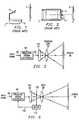
- Standard overhead projectors which have been used for many years, project images from a thin transparent plastic sheet to a screen 2.
- Projector I includes a base 1a, housing a light source, and a lens 1b. The transparency is placed on top of base la where light emitted from the light source shines through the transparency. Lens 1b directs the image to screen 2.
- a disadvantage of a standard overhead projection system is that it cannot interface with a computer. The system transmits only the image printed on the transparency. Other disadvantages of standard overhead projection system are that it is too heavy to be easily portable, it produces a lot of heat, and it consumes a lot of power.
- BARCO Data 600 manufactured by BARCO Projection Systems and shown in prior art FIG. 2.
- the BARCO Data 600 uses three monochrome CRT (Cathode Ray Tube) projection tubes 4, each projecting a red, green or blue image which is converged by use of colored lenses and optics to create a color picture on screen 5.
- Projection system 3 can be interfaced to a computer (not shown), allowing images displayed on the computer's CRT to also be displayed on screen 5.
- a primary disadvantage of this type of projection system is that it is large because of the physical depth required by the CRT's. Furthermore, this type of projection system is heavy due to the optics and mechanical packaging required to support a large volume apparatus.
- What is needed is a projection system which takes up less space, uses less power, and generates less heat than CRT overhead projection systems, but also interfaces to computers, and is capable of displaying multimedia images.
- a field emission device projector apparatus for projecting a field emission device image onto a surface comprising, circuitry responsive to an input signal for generating a field emission device display signal, a first field emission device comprising an emitter plate and an anode plate, said first field emission device responsive to said display signal for displaying an image, said anode plate coupled to a voltage source providing a voltage of less than 5,000 volts, and means for projecting said image onto said surface.
- a field emission device is used to create a projection system.
- the projection system may use a monochrome FED whose image is projected through a focusing lens to a surface separate from the projection system.
- a single monochrome FED can project the proper image through a color wheel to create a color image which is projected by a focusing lens onto a screen or wall.
- a first FED which projects a red image
- a second FED which projects a green image
- a third FED which projects a blue image
- three clear focusing lenses create a full color image on a screen. In this configuration, if the three lenses are colored red, green and blue, then the three FEDs need only present the image data for each color in black, grey, and white.
- the FED projection system could also utilize a color FED and a clear focusing lens to create a full color image on a screen.
- This full color FED could create its color image by using red, green, and blue phosphor stripes in the anode which are energized with a cathode having either full pixels or sub pixels.
- the FED projection system provides a three-dimensional display on the screen.
- FIG. 1 is a prior art standard projection system.
- FIG. 2 is a prior art overhead projection system which interfaces to a computer.
- FIG. 3 is a first embodiment of a FED projection system.
- FIG. 4 is a prior art cross-sectional view of a portion of a field emission display having color stripes.
- FIG. 5 is a prior art cross-sectional view of a portion of a field emission display having a single phosphor layer.
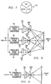
- FIG. 6 is a second embodiment of a FED projection system.
- FIG. 7 is a front view of the color wheel shown in FIG. 6.
- FIG. 8 is a third and fourth embodiment of a FED projection system.
- FIG. 9 is a fifth embodiment of FED projection system.
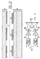
- FIG. 10 is a prior art cross-sectional view of a portion of a field emission display having sub pixels in accordance with a sixth embodiment.
- FIG. 11 is a seventh embodiment of a FED projection system.
- FIG. 3 shows a first preferred embodiment of the present invention.
- a field emission device (FED) projection system is constructed by creating an image on a monochrome FED 10 which is projected by focusing lens 20 onto a large surface such as a screen or wall 30.
- FED 10 is coupled to projection system electronics 40 which receives an input signal on line 50 and then sends the data and control signals which are necessary to create a FED image to FED 10.
- Input signal 50 can be provided by any multimedia source such as a TV, a VCR, a satellite, or a computer.
- System electronics 40 receives the input signal on line 50 and then generates the data and control signals needed by FED 10 to display the correct images.
- the luminescence needed to correctly display the images created by FED 10 on a separate surface 30 is provided by the FED 10.
- the technique for providing the proper luminescence by FED 10 is also explained in more detail below.
- a FED flat panel display arrangement is disclosed in U.S. Patent No. 4,857,799, "Matrix-Addressed Flat Panel Display,” issued Aug. 15, 1989, to Charles A. Spindt et al., incorporated herein by reference.
- This arrangement includes a matrix array of individually addressable light generating means of the cathodoluminescent type having cathodes combined with luminescing means of the CRT type which reacts to electron bombardment by emitting visible light.
- Each cathode is itself an array of thin film field emission cathodes on a backing plate, and the luminescing means is provided as a phosphor coating on a transparent face plate which is closely spaced to the cathodes.
- the backing plate disclosed in the Spindt et al. ('799) patent includes a large number of vertical conductive stripes which are individually addressable.
- Each cathode includes a multiplicity of spaced-apart electron emitting tips which project upwardly from the vertical stripes on the backing plate toward the face plate.
- An electrically conductive gate electrode arrangement is positioned adjacent to the tips to generate and control the electron emission.
- the gate electrode arrangement comprises a large number of individually addressable, horizontal stripes which are orthogonal to the cathode stripes, and which include apertures through which emitted electrons may pass.
- the gate electrode stripes are common to a full row of pixels extending across the front face of the backing structure, electrically isolated from the arrangement of cathode stripes.
- the anode is a thin film of an electrically conductive transparent material, such as indium tin oxide, which covers the interior surface of the face plate. Deposited onto this metal layer is a luminescent material, such as phosphor, that emits light when the anode is bombarded by electrons released from the cathode.
- an electrically conductive transparent material such as indium tin oxide
- the matrix array of cathodes is activated by addressing the orthogonally related cathodes and gates in a generally conventional matrix-addressing scheme.
- the appropriate cathodes of the display along a selected stripe, such as along one column, are energized while the remaining cathodes are not energized.
- Gates of a selected stripe orthogonal to the selected cathode stripe are also energized while the remaining gates are not energized, with the result that the cathodes and gates of a pixel at the intersection of the selected horizontal and vertical stripes will be simultaneously energized, emitting electrons so as to provide the desired pixel display.
- the Clerc ('820) patent discloses a trichromatic field emission flat panel display having a first substrate comprising the cathode and gate electrodes, and having a second substrate facing the first, including regularly spaced, parallel conductive stripes comprising the anode electrode. These stripes are alternately covered by a first material luminescing in the red, a second material luminescing in the green, and a third material luminescing in the blue, the conductive stripes covered by the same luminescent material being electrically interconnected.
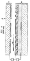
- FIG. 4 A typical prior art FED color display is shown in FIG. 4.
- the typical FED comprises an anode 70, and an emitter 80.
- the anode 70 has red, green, and blue color phosphor stripes 90.
- the image created by the phosphor stripes is observed from the anode side which is opposite to the phosphor excitation, as indicated in FIG. 4.
- a typical prior art monochrome display shown in FIG. 5, comprises anode 70, emitter 80, and a single phosphor coating 100 deposited over conductive film 110 of anode 70.
- a fixed voltage is applied on anode 70 and the voltage on emitter 80 is modulated to create gray-scale variations.
- true scaling information is not intended to be conveyed by the relative sizes and positioning of the elements of anode plate 70 and the elements of emitter plate 80 as depicted in FIGs 4 and 5.
- FIG. 4 there are ten sets, or matrixes, of microtips 120 and there are three color stripes 90 per display pixel.
- the process of producing each display frame using a typical trichromatic field emission display 10 includes applying an accelerating potential to the red anode stripes while sequentially addressing the row lines (gate electrodes) with the corresponding red video data for that frame applied to the column lines (cathode electrodes), switching the accelerating potential to the green anode stripes while sequentially addressing the rows lines for a second time with the corresponding green video data for that frame applied to the column lines, and switching the accelerating potential to the blue anode stripes while sequentially addressing the row lines for a third time with the corresponding blue video data for that frame applied to the column lines. This process is repeated for each display frame.
- FED 10 has an anode plate which has an electroluminescent phosphor coating facing an emitter plate.
- the phosphor coating creates the images displayed by the FED 10.
- FED's used for applications where the image on the FED need only be projected a few feet have an luminescence of around 120 ft-L (foot lamberts).
- standard projection systems operate at a luminance of around 600 ft-L to properly project an image.
- triode mode techniques commonly known in the industry the correct luminance level of the FED is created through adjusting the voltage on the anode of the FED.
- a field emission device projection system is constructed by creating an image on a monochrome FED 10 which is projected by a focusing lens 20 onto a large surface such as a screen or wall 30.
- FED 10 is coupled to projection system electronics 40 which receives an input signal on line 50 and then sends the data and control signals which are necessary to create a FED image to FED 10.
- a color wheel 150 is disposed between FED 10 and focusing lens 20. As shown in FIG. 7, color wheel 150 is divided into three color sections. When motor 130, shown in FIG. 6, rotates color wheel 150, either a red, green or blue colored film section transforms the monochrome image projected by FED 10 into a color image which is then projected through lens 20 onto screen 30.
- Motor 130 rotates the color wheel 150 at a speed synchronous to the frame rate which will place each of the three color portions of wheel 150 in front of FED 10 once during each frame.
- a typical frame rate is 60Hz.
- a signal is sent on line 140 which will cause FED 10 to turn on and display the image for the red color.
- the FED 10 is turned off and the green portion of the wheel 150 is placed between FED 10 and lens 20.
- a signal is now sent on line 140 which will cause FED 10 to turn on and display the image for the green color.
- the FED 10 is turned off and the blue portion of the wheel 150 is placed between FED 10 and lens 20.
- a signal is now sent on line 140 which will cause FED 10 to turn on and display the image for the blue color. Even though the red, green, and blue images are each displayed sequentially during one frame, the user's eye integrates the three single color images and therefore the user sees only a full color image.
- a field emission device projection system is constructed by creating a red image on a first monochrome FED 10, a green image on a second monochrome FED 10, and a blue image on a third monochrome FED 10. These three images are then projected by three focusing lenses 20 onto a large surface such as a screen or wall 30.
- Each FED 10 is coupled to projection system electronics 40 which receives an input signal on line 50 and then sends the data and control signals which are necessary to create a FED image to FED 10.
- the first monochrome FED contains only red phosphors and therefore projects the red image through a clear focusing lens 20 to screen 30.
- the second monochrome FED which has only green phosphors
- the third monochrome FED which only has blue phosphors
- the result is that a full color image is displayed on screen 30.
- the first, second and third monochrome FED's 10 of FIG. 8 may display the correct red, green and blue image using black/grey/white images which are projected through either a red, green or blue colored focusing lens 20. This configuration would also create a full color image on screen 30.
- a field emission device projection system is constructed by creating a color image on a FED 10 which is projected by a clear focusing lens 20 onto a large surface such as a screen or wall 30.
- FED 10 is coupled to projection system electronics 40 which receives an input signal on line 50 and then sends the data and control signals which are necessary to create a FED image to FED 10.
- the FED 10 contains the red, green, and blue phosphor color stripes in its anode discussed above with reference to FIG. 4. Each of the three color stripes is sequentially activated and then deactivated once during each frame. The correct image is presented by the cathode for the each color as the red, green, and blue phosphor stripes are energized.
- the user's eye integrates the three images and so the user sees a full color image.
- the color FED 10 shown in FIG. 9 is physically modified.
- a standard FED employs the use of color stripes, as shown in FIG. 4. As each color stripe 90 is energized, it attracts electrons from each of the ten matrixes 120 which comprise one pixel. However, as shown in FIG. 10, it is also common to divide each pixel into three sub pixels 160 where each stripe 90 receives its electrons from its dedicated sub pixel 160 which is located directly opposite and facing color stripe 90. Sub pixels can be electrically isolated by leaving a vacuum space between the sub pixels or by depositing a dielectric between the sub pixels.
- a three dimensional field emission device projection system is created by using two FED's 10 and two lenses 20.
- This embodiment facilitates the implementation of standard three-dimensional display imaging techniques.
- One example is binocular stereoscopic imaging using polarization coding. This technique provides a true full-color three-dimensional display.
- the full-color images on FED's 10 would be projected onto a screen 30.
- This projection system would project a first and second image so that they are substantially superimposed with respect to each other on the screen.
- the light from the first image is filtered to have a polarization orientation which is perpendicular to the light of the second image.
- each eye would look through a lens polarized at a 90° angle from the lens for the other eye and each eye therefore perceives only one of the stereoscopic images.
- all FED projection systems described above can be configured as a front projection system, as shown in FIGs. 3, 6, 8, and 9, or as a rear projection system.
- one set of projection system electronics 40 could provide the proper image information to all three FED's in FIG. 8
- FED 10 may comprise a plurality of cathodes and a single anode.
- This FED configuration is described fully in U.S. Patent Application Serial No. 08/314,036, "Creation of a Large Field Emission Device Display Through The Use of Multiple Cathodes And a Single Anode", filed September 28, 1994 (Texas Instruments, Inc., Docket No. TI-18971), incorporated herein by reference.
- One of the main advantages of this alternative configuration is that multiple images can be displayed simultaneously by each cathode. Therefore, there is more flexibility in the quantity and variety of data displayed on the screen at any one time.
- FED projection system has numerous advantages. FED technology consumes less power and contains higher reliability electronics than current projection system technologies such as standard overhead projectors. Additionally, the FED projection system is approximately 1/4 the volume of current projection systems such as BARCO-type CRT systems. Furthermore, FED projection systems are capable of interfacing to a laptop or a desktop size computer, as will as to a variety of other data and video sources. Screen displays up to 60" can be obtained while maintaining a picture brightness equal to or greater than current projection systems.
- the FED projector system is capable of multimedia presentations. Therefore this system can display still images or video images. Also the system can display images in color or monochrome.
- FED 10 has an anode plate which has an electroluminescent phosphor coating facing an emitter plate.
- the phosphor coating creates the images displayed by the FED 10.
- FED's used for applications where the image on the FED need only be projected a few feet have a luminescence of around 120 ft-L (foot lamberts).
- standard projection systems operate at a .luminance of around 600 ft-L to properly project an image.
- the increased luminance needed in the preferred embodiment is obtained by increasing the voltage on the anode plate of FED 10.
- Using standard triode mode techniques commonly known in the industry a ten-fold increase in voltage results in a one hundred-fold increase in luminance. Therefore the voltage of the anode does not have to be increased greatly above the standard 700V level used for notebook computer applications to increase the standard luminance ofthe panel from 120 ft-L to 600 ft-L.
- the anode of FED panel 10 will be powered at a voltage below 5,000V and will produce a luminance up to approximately 800 ft -L.
- the spacing between the anode and cathode plates will be increased from 200 microns (commonly used in lap to computer applications) to less than 1 cm. The exact spacing between the anode and cathode plates is determined by the FED projection system application.
- the additional heat is mechanically dissipated by adding metal fins or a frame to the structure of the FED panel.
- a field emission device projection system is constructed by creating an image on a monochrome FED 10 which is projected by a focusing lens 20 onto a large surface such as a screen or wall 30.
- FED 10 a field emission device projection system
Applications Claiming Priority (2)
| Application Number | Priority Date | Filing Date | Title |
|---|---|---|---|
| US32483294A | 1994-10-18 | 1994-10-18 | |
| US324832 | 1994-10-18 |
Publications (2)
| Publication Number | Publication Date |
|---|---|
| EP0708431A2 true EP0708431A2 (fr) | 1996-04-24 |
| EP0708431A3 EP0708431A3 (fr) | 1996-12-04 |
Family
ID=23265289
Family Applications (1)
| Application Number | Title | Priority Date | Filing Date |
|---|---|---|---|
| EP95307437A Withdrawn EP0708431A3 (fr) | 1994-10-18 | 1995-10-18 | Dispositif de projection utilisant un dispositif d'affichage à effet de champ |
Country Status (5)
| Country | Link |
|---|---|
| US (1) | US5669690A (fr) |
| EP (1) | EP0708431A3 (fr) |
| JP (1) | JPH08214241A (fr) |
| KR (1) | KR960016516A (fr) |
| TW (1) | TW278307B (fr) |
Cited By (5)
| Publication number | Priority date | Publication date | Assignee | Title |
|---|---|---|---|---|
| WO2000014704A1 (fr) * | 1998-09-03 | 2000-03-16 | Yingui Zhou | Technique de formation d'image a balayage de spot et appareil correspondant |
| DE10043346A1 (de) * | 2000-08-23 | 2002-03-07 | 4D Vision Gmbh | Autostereoskopische Bildwiedergabeeinrichtung und Herstellungsverfahren für ein elektrisch leitendes Filterarray |
| US6777869B2 (en) * | 2002-04-10 | 2004-08-17 | Si Diamond Technology, Inc. | Transparent emissive display |
| US7046271B2 (en) | 2000-01-25 | 2006-05-16 | X3D Technologies Gmbh | Method and system for the three-dimensional representation |
| US8120646B2 (en) | 2003-05-30 | 2012-02-21 | Phoenix 3D, Inc. | Spatial representation assembly |
Families Citing this family (10)
| Publication number | Priority date | Publication date | Assignee | Title |
|---|---|---|---|---|
| US6064521A (en) * | 1997-05-14 | 2000-05-16 | Burke; Douglas | Polarizing resonant scattering three dimensional image screen and display systems |
| US6618031B1 (en) | 1999-02-26 | 2003-09-09 | Three-Five Systems, Inc. | Method and apparatus for independent control of brightness and color balance in display and illumination systems |
| AUPQ494000A0 (en) * | 2000-01-04 | 2000-02-03 | Digislide International Pty Ltd | Dual image slide and/or video projector |
| US6353508B1 (en) | 2000-01-06 | 2002-03-05 | Douglas Burke | Polarizing fresnel enhanced apparent depth viewing screens and systems |
| US20030103193A1 (en) * | 2001-12-05 | 2003-06-05 | O'donnell Eugene Murphy | Use of resonant microcavity display FED for the illumination of a light valve projector |
| KR20030061173A (ko) * | 2002-01-11 | 2003-07-18 | 엘지전자 주식회사 | 전계 방출 디바이스를 이용한 프로젝션 장치 |
| JP2003348501A (ja) * | 2002-05-23 | 2003-12-05 | Olympus Optical Co Ltd | 画像表示装置 |
| KR100660466B1 (ko) * | 2005-02-01 | 2006-12-22 | 남상희 | 에프이디 소자를 이용한 엑스레이 검출기판 |
| WO2008102971A1 (fr) * | 2007-02-20 | 2008-08-28 | Daegu Gyeongbuk Institute Of Science & Technology | Lecteur multimédia affichant deux images de projection |
| TWI561773B (en) | 2014-08-06 | 2016-12-11 | Delta Electronics Inc | Six-primary solid state illuminator and operating method using the same |
Citations (4)
| Publication number | Priority date | Publication date | Assignee | Title |
|---|---|---|---|---|
| US4857799A (en) | 1986-07-30 | 1989-08-15 | Sri International | Matrix-addressed flat panel display |
| US4940916A (en) | 1987-11-06 | 1990-07-10 | Commissariat A L'energie Atomique | Electron source with micropoint emissive cathodes and display means by cathodoluminescence excited by field emission using said source |
| US5194780A (en) | 1990-06-13 | 1993-03-16 | Commissariat A L'energie Atomique | Electron source with microtip emissive cathodes |
| US5225820A (en) | 1988-06-29 | 1993-07-06 | Commissariat A L'energie Atomique | Microtip trichromatic fluorescent screen |
Family Cites Families (5)
| Publication number | Priority date | Publication date | Assignee | Title |
|---|---|---|---|---|
| US5194884A (en) * | 1991-04-08 | 1993-03-16 | Parker Norman W | Image projection system employing a cold cathode field-emission image source |
| US5337224A (en) * | 1992-12-04 | 1994-08-09 | Field John B A | Electroluminescent transparency illuminator |
| US5371543A (en) * | 1993-03-03 | 1994-12-06 | Texas Instruments Incorporated | Monolithic color wheel |
| US5521660A (en) * | 1994-09-29 | 1996-05-28 | Texas Instruments Inc. | Multimedia field emission device portable projector |
| US5477284A (en) * | 1994-12-15 | 1995-12-19 | Texas Instruments Incorporated | Dual mode overhead projection system using field emission device |
-
1995
- 1995-10-03 US US08/538,328 patent/US5669690A/en not_active Expired - Lifetime
- 1995-10-13 KR KR1019950035300A patent/KR960016516A/ko not_active Application Discontinuation
- 1995-10-17 JP JP7268565A patent/JPH08214241A/ja active Pending
- 1995-10-18 EP EP95307437A patent/EP0708431A3/fr not_active Withdrawn
- 1995-11-23 TW TW084112461A patent/TW278307B/zh active
Patent Citations (5)
| Publication number | Priority date | Publication date | Assignee | Title |
|---|---|---|---|---|
| US4857799A (en) | 1986-07-30 | 1989-08-15 | Sri International | Matrix-addressed flat panel display |
| US4940916A (en) | 1987-11-06 | 1990-07-10 | Commissariat A L'energie Atomique | Electron source with micropoint emissive cathodes and display means by cathodoluminescence excited by field emission using said source |
| US4940916B1 (en) | 1987-11-06 | 1996-11-26 | Commissariat Energie Atomique | Electron source with micropoint emissive cathodes and display means by cathodoluminescence excited by field emission using said source |
| US5225820A (en) | 1988-06-29 | 1993-07-06 | Commissariat A L'energie Atomique | Microtip trichromatic fluorescent screen |
| US5194780A (en) | 1990-06-13 | 1993-03-16 | Commissariat A L'energie Atomique | Electron source with microtip emissive cathodes |
Cited By (5)
| Publication number | Priority date | Publication date | Assignee | Title |
|---|---|---|---|---|
| WO2000014704A1 (fr) * | 1998-09-03 | 2000-03-16 | Yingui Zhou | Technique de formation d'image a balayage de spot et appareil correspondant |
| US7046271B2 (en) | 2000-01-25 | 2006-05-16 | X3D Technologies Gmbh | Method and system for the three-dimensional representation |
| DE10043346A1 (de) * | 2000-08-23 | 2002-03-07 | 4D Vision Gmbh | Autostereoskopische Bildwiedergabeeinrichtung und Herstellungsverfahren für ein elektrisch leitendes Filterarray |
| US6777869B2 (en) * | 2002-04-10 | 2004-08-17 | Si Diamond Technology, Inc. | Transparent emissive display |
| US8120646B2 (en) | 2003-05-30 | 2012-02-21 | Phoenix 3D, Inc. | Spatial representation assembly |
Also Published As
| Publication number | Publication date |
|---|---|
| US5669690A (en) | 1997-09-23 |
| JPH08214241A (ja) | 1996-08-20 |
| TW278307B (fr) | 1996-06-11 |
| EP0708431A3 (fr) | 1996-12-04 |
| KR960016516A (ko) | 1996-05-22 |
Similar Documents
| Publication | Publication Date | Title |
|---|---|---|
| US5669690A (en) | Multimedia field emission device projection system | |
| US6611241B1 (en) | Modular display system | |
| US6577286B1 (en) | Device and method of displaying images | |
| JP3295669B2 (ja) | 改良された電子蛍光表示装置 | |
| US5121233A (en) | Multi-color display | |
| KR100759413B1 (ko) | 발광 장치와 이 발광 장치를 백라이트 유닛으로 사용하는액정 표시장치 | |
| JPH08506686A (ja) | ダイオード構造のフラットパネルディスプレイ | |
| SE461692B (sv) | Saett foer alstring av elektroniskt styrbara faergelement och faergpresentationsenhet baserad paa saettet | |
| JP2002503832A (ja) | タイル張り電子ディスプレイ構造 | |
| US5655940A (en) | Creation of a large field emission device display through the use of multiple cathodes and a seamless anode | |
| US5477284A (en) | Dual mode overhead projection system using field emission device | |
| WO1996001028A1 (fr) | Appareil et procede video a images tridimensionnelles | |
| US20020141056A1 (en) | Stereoscopic video display device and dot-shaped light emission member and dot-shaped light transmission member | |
| US5521660A (en) | Multimedia field emission device portable projector | |
| US5194884A (en) | Image projection system employing a cold cathode field-emission image source | |
| US5578902A (en) | Field emission display having modified anode stripe geometry | |
| KR100863959B1 (ko) | 발광 장치 및 이를 구비한 표시 장치 | |
| Sobel | Flat-Panel Displays | |
| US5527651A (en) | Field emission device light source for xerographic printing process | |
| US20040100426A1 (en) | Field emission display brightness uniformity compensation system and method | |
| EP0518612A1 (fr) | Dispositif de visualisation pour des dispositifs électroniques | |
| JPH01117251A (ja) | 画像表示装置 | |
| JP2006184462A (ja) | 画像表示装置およびその駆動方法 | |
| Awamoto et al. | The big picture | |
| JPH02203381A (ja) | ディスプレイ装置 |
Legal Events
| Date | Code | Title | Description |
|---|---|---|---|
| PUAI | Public reference made under article 153(3) epc to a published international application that has entered the european phase |
Free format text: ORIGINAL CODE: 0009012 |
|
| AK | Designated contracting states |
Kind code of ref document: A2 Designated state(s): DE FR GB IT NL |
|
| PUAL | Search report despatched |
Free format text: ORIGINAL CODE: 0009013 |
|
| AK | Designated contracting states |
Kind code of ref document: A3 Designated state(s): DE FR GB IT NL |
|
| 17P | Request for examination filed |
Effective date: 19970604 |
|
| STAA | Information on the status of an ep patent application or granted ep patent |
Free format text: STATUS: THE APPLICATION IS DEEMED TO BE WITHDRAWN |
|
| 18D | Application deemed to be withdrawn |
Effective date: 19980501 |