EP0708339A2 - Datensammlung und -verarbeitung für digitale Wechselstromsystemüberwacher/-analysierer - Google Patents
Datensammlung und -verarbeitung für digitale Wechselstromsystemüberwacher/-analysierer Download PDFInfo
- Publication number
- EP0708339A2 EP0708339A2 EP95116296A EP95116296A EP0708339A2 EP 0708339 A2 EP0708339 A2 EP 0708339A2 EP 95116296 A EP95116296 A EP 95116296A EP 95116296 A EP95116296 A EP 95116296A EP 0708339 A2 EP0708339 A2 EP 0708339A2
- Authority
- EP
- European Patent Office
- Prior art keywords
- sampling
- sampling rate
- samples
- rate
- waveforms
- Prior art date
- Legal status (The legal status is an assumption and is not a legal conclusion. Google has not performed a legal analysis and makes no representation as to the accuracy of the status listed.)
- Granted
Links
Images


Classifications
-
- G—PHYSICS
- G01—MEASURING; TESTING
- G01R—MEASURING ELECTRIC VARIABLES; MEASURING MAGNETIC VARIABLES
- G01R21/00—Arrangements for measuring electric power or power factor
- G01R21/133—Arrangements for measuring electric power or power factor by using digital technique
- G01R21/1331—Measuring real or reactive component, measuring apparent energy
-
- G—PHYSICS
- G01—MEASURING; TESTING
- G01R—MEASURING ELECTRIC VARIABLES; MEASURING MAGNETIC VARIABLES
- G01R19/00—Arrangements for measuring currents or voltages or for indicating presence or sign thereof
- G01R19/25—Arrangements for measuring currents or voltages or for indicating presence or sign thereof using digital measurement techniques
Definitions
- This invention relates to data collection and processing of that data in digital apparatus which performs metering functions and can also perform harmonic distortion analysis of the waveform in an ac electrical power system.
- monitors for ac power systems incorporate microcomputers for calculating various electrical parameters such as rms currents and voltages, peak currents and voltages, power, energy, power factor, and the like.
- the sampling rate at which the analog waveforms of the electrical power system are digitized for input to the microprocessor is a compromise between the high sampling rate desired for increased accuracy, and lower rates imposed by computing time needed for the processor to calculate the various electrical parameter desired as outputs.
- Waveform analyzers are used for oscillographic analysis of the waveforms in the ac electrical power system and can also be used to determine the harmonic content of the waveform.
- a signal must be sampled at twice the highest fluency to be detected.
- a waveform must be sampled at twice the frequency of the highest harmonic to be extracted.
- a 60 Hz ac signal must be sampled at least at 6 KHz in order to extract the 50th harmonic.
- This high sampling rate places a burden on the microcomputer.
- only the monitoring function such as calculation of the various voltages and currents, power and the like are performed in the microcomputer of the device.
- the raw digital waveform data is sent to a remote computer with greater computing capacity for performing the harmonic analysis.
- circuit breakers also utilize microcomputers in the trip unit. Such digital trip units can perform monitoring functions in addition to the protection functions.
- Some of these circuit breakers employ what is known as an equivalent sampling technique to increase accuracy without placing an undue burden on the microprocessor.
- the equivalent sampling technique the ac waveforms are sampled a selected number of times per cycle with a delay of a fraction of a cycle before another cycle of samples is taken at the same sampling rate. Thus, the sampling instants are "bumped" each cycle by the selected fraction of a cycle. The data collected over a number of such "bumped" cycles are then used to calculate the various parameters.
- an effective rate of 64 samples per cycle can be realized by sampling for one cycle, delaying for 1/64 of a cycle and then taking another 16 samples at the rate of 16 samples per cycle. This is repeated until four cycles of data are accumulated; however, 4-1/16 cycles are required to generate this data. Thus, this is not synchronous sampling, but then synchronous sampling is not necessary to perform the monitoring and protection functions.
- sampling must be synchronous in order to perform the Fourier analysis used for calculating harmonic distortion.
- synchronous sampling it is meant that an integer number of samples are taken per cycle.
- a high sampling rate is required to detect the full range of harmonic information needed to make the harmonic analysis.
- the Fourier analysis of that data requires a considerable amount of computation time. The result is that a very high demand is placed upon the microcomputer, especially if extensive monitoring is also to be performed by the device.
- sampling of the ac waveforms is performed at a first, slow, sampling rate for gathering the data for the monitoring or protection functions, and sampling at a second, higher, sampling rate to digitize the waveforms for harmonic distortion analysis.
- a form of equivalent sampling is used for the slow sampling, while synchronous sampling is used during high speed sampling to meet the requirements for Fourier analysis of the harmonic content of the waveforms.
- sampling is performed at the slow rate; however, momentary sampling at the high speed rate can be implemented automatically upon the occurrence of particular events, on manual command, or at specified times.
- the two sampling rates are implemented through organizing the sampling into sampling frames each of which comprises a predetermined number of repetitions of sampling for a selected number of cycles followed by a delay of a fraction of a cycle.
- Sampling at the high speed rate is performed in no more than one repetition of the selected number of cycles during a sampling frame.
- equivalent sampling is used for sampling at the slow speed rate during the sampling frame, while the high speed sampling, if used during a frame, is performed synchronously.
- the high speed sampling is performed at a rate which is an integer multiple of the slow speed rate, so that slow speed data can be extracted from the high speed data for continuous calculation of the monitored electrical parameters.
- a sampling frame comprises four repetitions of sampling for two cycles at 32 samples per cycle with a fractional delay of 1/128th of a cycle between repetitions.
- a frame requires 8 1/32 cycles, providing an equivalent sampling rate of 128 samples per cycle.
- the high speed sampling is performed at 128 samples per cycle, which being four times the slow speed sampling rate, permits samples at the rate of 32 per cycle to be extracted from the high speed data.
- the tasks performed by the microcomputer are allocated to provide this computational time for the harmonic analysis while still devoting sufficient computational time to monitoring so that a full spectrum of parameters can be tracked.
- Periodic interrupts which initiate sampling also regulate the performance of the calculations carried out by the microcomputer.
- Specific tasks are assigned to be performed at specified interrupts throughout the sampling frame.
- the Fourier analysis computations are broken down into smaller steps which are performed on each of either the odd or even interrupts during a sampling frame. All of the other functions performed by the microprocessor are allocated to the other of the odd or even interrupts. The data gathered during one sampling frame are processed during the next sampling frame.
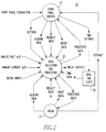
- the monitor/analyzer 1 of the invention is used to monitor and analyze an ac electrical power system 3 such as a power distribution system.
- the power distribution system 3 illustrated has three phase conductors 5A, B and C, a neutral conductor 5N and a ground conductor 5G.
- Current transformers 5A, B, C, N and G sense current flowing in each of these conductors while phase to neutral voltages are sensed by the potential transformers 9A, B, and C, and neutral to ground voltage is caused by transformer 9N.
- a ranging circuit 11 converts the current and the voltage signals from -10 to 0 to +10 volt signals for conversion by analog to digital (A/D) converter 13 for input to a digital processor 15.
- the A/D converter 13 samples the analog voltages and currents at sampling rates determined by interrupts generated by the digital processor 15. These interrupts are generated selectively at a first, slow speed sampling rate, or a second, high speed sampling rate. In the exemplary device, the slow speed sampling rate is 32 samples per cycle and the high speed rate is 128 samples per cycle. During low speed sampling, the A/D converter 13 samples all five currents and all four voltages. For high speed sampling, again all currents are sampled, but only the three phase voltages are digitized for input to the processor. Bach of these currents and voltages is sampled on each interrupt.
- the digital processor 15 utilizes the data generated by these digital samples to generate values of two sets of electrical parameters.
- the first set of parameters is related to the monitoring function and includes metered parameters such as: rms currents and voltages, peak currents and voltages, minimum currents and voltages, power factor, watts, Vars, volt-amps, total harmonic factor, K-factor, CBMEA derating factor, and the like.
- the second set of parameters calculated by the digital processor 15 are the individual harmonic coefficients.
- the present invention organizes data collection and processing so that a maximum number of parameters can be monitored continuously while also providing the capability for simultaneous calculation of harmonic content.
- the digital processor 15 has an input/output (I/O) 17 through which the processor 15 is connected to a front panel 19.
- the front panel 19 serves as the interface with the user. It is through the front panel that the user can control the operation of the monitor/analyzer 1 and monitor the ac electrical power system 3.
- the input/output device 17 also interfaces the digital processor 15 with contact inputs through a digital input. Relay outputs and analog outputs are also provided through the input/output device 17.
- the digital processor 15 can also communicate with a remote processor through a communications link 21. Through this communications link 21 the monitor/analyzer 1 can provide information to and/or be controlled by a remote processor (not shown).
- FIG. 2 illustrates a data flow diagram 23 or the monitor/analyzer 1 shown in Figure 1.
- the sensed analog voltages and current are converted to digital signals for input to the data collection and processing function 25 where the data is processed in accordance with settings received from a front panel control 27. Such settings are input to the control 27 through front panel push buttons. These push buttons can also be used to request data and to acquire it for a display on the front panel when available.
- Data collection and processing is performed using time data provided by a real time clock 29 which can be set from the front panel. External inputs such as contact closures are also processed.
- data can be exchanged with a remote computer through a communications link such as the Incom® network 31 or any other suitable communications link. This provides the capability for the monitor/analyzer 1 to interface with a remote unit in the same manner that it interfaces with the front panel.
- relay outputs can also be generated.
- FIG. 3 illustrates the sampling technique used in accordance with the invention.
- two sampling rates are used.
- equivalent sampling is employed with the slow speed sampling in order to improve accuracy.
- Equivalent sampling at low speed with selectable high speed sampling is implemented by sampling in frames.
- Each sampling frame 35 comprises repetitions 371-374 of sampling for a selected number of cycles followed by a delay ⁇ , which is a fraction of a cycle.
- the selected number of cycles is 2 and the frame constitutes four repetitions of 371-374 sampling for two cycles followed by a delay ⁇ .
- the exemplary frame 35 is equal to eight cycles + 4 ⁇ .
- the slow speed sampling rate is 32 samples per cycle and ⁇ is made equal to 1/128 of a cycle so that the sampling frame 35 is equal to 8 1/32 cycles of the fundamental waveform 33. This provides an equivalent sampling rate of 128 samples per cycle.
- High speed sampling can be implemented in any one of the repetitions 371-374, but only one, during a sampling frame 35.
- high speed sampling when called for, is implemented in the third repetition 373 within the frame 35.
- Any one of the frames can be used for high speed sampling, but it is always the same repetition.
- the sampling can be synchronous, a requirement for Fourier analysis of the harmonic content of the waveform.
- synchronous it is meant that an integer number of samples are taken per cycle.
- the high speed sampling is carried out at a rate which is an integer multiple of the slow speed rate.
- the high speed rate is 128 samples per cycle which is four times the slow speed rate. This permits the slow speed data to be extracted from the high speed data, so that continuous data is available for the calculations performed using the slow speed sampling.
- the selected number of cycles in each repetition 37 is two in the exemplary embodiment, other numbers of cycles can be used. However, the number of cycles selected for each repetition sets the maximum number of cycles of high speed data that can be collected during a frame. Two cycles provides some averaging which would not be available if only one cycle of high speed data were collected. On the other hand, if the selected number of cycles is greater than two, the length of the frame is extended which can reduce the response to changes in amplitude of the waveforms which is pertinent to the monitoring function. A different number of repetitions 37 in the frame 35 can also be used; however, fewer repetitions would decrease the resolution of the equivalent sampling, and again an increased number of repetitions would decrease the response of calculations to changes in amplitude.
- the sampling at the high speed rate can be implemented automatically in response to conditions in the ac electrical power distribution system 3, such as for instance an overcurrent condition, a trip, a low voltage condition, or the like.
- high speed sampling can be commanded through the front panel or remotely through the communications link.
- high speed sampling can be initiated by a timer. In any case, and especially in the case of an automatic response to an abnormal condition, high speed sampling can be performed in a series of successive sampling frames, and in the exemplary system, up to seven successive frames.
- one-half of the computation time available in the microprocessor is assigned to perform that function.
- These computations which generate values for the individual harmonics as a percentage of the fundamental for the analyzed waveforms, are only performed during the slow speed sampling.
- alternate interrupts for instance the odd interrupts, initiate analog to digital conversion, and also trigger the computations for the Fourier analysis.
- the remaining tasks are assigned to the even interrupts, which also initiate analog to digital conversions.
- Table 1 illustrates the exemplary assignment of tasks to the even interrupts. As the slow sampling rate is 32 samples per cycle, there are 16 even interrupts per cycle to which tasks can be assigned.
- the tasks assigned to even interrupts are delayed by high speed sampling, and those which normally would have been performed during the third repetition, 373, are instead performed during the fourth repetition 374.
- the tasks performed include calculation of total harmonic distortion (THD). These calculations are performed on the even interrupts, as they are simple calculations which only require data generated by low speed sampling the tasks performed during any given frame utilize data collected from the previous frame.
- TDD total harmonic distortion
- each low speed sampling interrupt includes squaring the currents and voltages and adding the resultant value to a sum for calculation of the rms values. Similarly, the voltages and currents are multiplied together and summed for the power calculations.
- the set of data collected on a given interrupt is processed in this manner on the next interrupt.
- the cumulative results of this preprocessing during each frame are then saved for use in the performance of tasks requiring such data during the next frame.
- one of the tasks performed on the even interrupts is to determine the rms current by taking the square root of the sum of the squares accumulated during the previous frame.
- While the slow speed sampling is performed at an equivalent sampling rate of 128 samples per cycle, in fact only 32 samples are taken in each cycle with the samples in each subsequent cycle delayed by the amount ⁇ .
- a true 128 samples per cycle are taken during the high speed sampling.
- this sampling rate is an integer multiple of the slow speed sampling rate
- the slow speed sampling data is extracted from the high speed data.
- On each high speed interrupt the raw values of the currents and voltages are sampled and stored. Squaring and summing of the currents and voltages is only carried out for samples taken at every fourth sample during a high speed sampling. However, the processing of the currents and voltages to determine the squared sum is distributed over the four interrupts, as all of the processing does not have to be completed for each interrupt.
- phase rotation One of the tasks performed on the even interrupts is the determination of phase rotation. This is accomplished by calculating from the phase to neutral voltages, two of the phase-to-phase voltages. One of these phase-to-phase voltages is phase shifted 90 degrees. This phase shifted phase-to-phase voltage and the other phrase-to-phase voltage are multiplied together. The polarity of the result determines the phase rotation.
- the period of the ac power is calculated periodically so that the sampling interval can be adjusted if necessary to provide synchronous sampling. Such adjustment of the sampling interval is not made during high speed sampling to avoid skewing of the results.
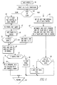
- FIG. 5 is a flow chart for the timer interrupt routine 39 implemented by the digital processor 15.
- BB time this routine is called, analog to digital conversion of the currents and voltages is initiated at 41. If sampling is being performed at the slow rate as determined at 43, the time interval for the next slow interrupt is set and the pointers for storing the slow speed data are set at 45. The currents and voltages from the previous sample are then squared and the power calculation from the previous sample is performed at 47. The power calculation is then added to an energy summation at 49. When eight cycles have been completed as determined at 51, the processed values for this frame are saved at 53. Then, the digitized currents and voltages generated by the a/d converter on this interrupt are saved at 55.
- the time for the next high speed interrupt and the data pointers for storing high speed data are set at 65.
- the pointers are incremented and checked at 67 and on every fourth high speed interrupt the slow speed data is saved.
- the high speed data is saved and the initial processing, such as squaring the currents or the voltages, is performed. If two cycles of high speed data have been collected as determined at 69, the FAST_DATA flag is reset at 71 so that the next time the timer interrupt routine 39 is called, slow speed sampling will be resumed.
Landscapes
- Physics & Mathematics (AREA)
- General Physics & Mathematics (AREA)
- Engineering & Computer Science (AREA)
- Power Engineering (AREA)
- Measurement Of Current Or Voltage (AREA)
- Remote Monitoring And Control Of Power-Distribution Networks (AREA)
- Complex Calculations (AREA)
- Supply And Distribution Of Alternating Current (AREA)
- Measuring Frequencies, Analyzing Spectra (AREA)
Applications Claiming Priority (2)
| Application Number | Priority Date | Filing Date | Title |
|---|---|---|---|
| US325711 | 1994-10-17 | ||
| US08/325,711 US5587917A (en) | 1994-10-17 | 1994-10-17 | Data collection and processing for digital AC power system monitor/analyzer |
Publications (3)
| Publication Number | Publication Date |
|---|---|
| EP0708339A2 true EP0708339A2 (de) | 1996-04-24 |
| EP0708339A3 EP0708339A3 (de) | 1997-11-19 |
| EP0708339B1 EP0708339B1 (de) | 2002-03-27 |
Family
ID=23269093
Family Applications (1)
| Application Number | Title | Priority Date | Filing Date |
|---|---|---|---|
| EP95116296A Expired - Lifetime EP0708339B1 (de) | 1994-10-17 | 1995-10-16 | Datenerfassung und -verarbeitung für digitale Wechselstromsystemüberwacher/-analysierer |
Country Status (9)
| Country | Link |
|---|---|
| US (1) | US5587917A (de) |
| EP (1) | EP0708339B1 (de) |
| JP (1) | JPH08211112A (de) |
| AU (1) | AU697726B2 (de) |
| BR (1) | BR9504836A (de) |
| CA (1) | CA2160655C (de) |
| DE (1) | DE69526023T2 (de) |
| NZ (1) | NZ280115A (de) |
| ZA (1) | ZA958629B (de) |
Cited By (6)
| Publication number | Priority date | Publication date | Assignee | Title |
|---|---|---|---|---|
| FR2753852A1 (fr) * | 1996-08-09 | 1998-03-27 | Siemens Ag | Dispositif de visualisation comportant une unite de calcul pour la reconnaissance d'un signal d'excitation et procede de reconnaissance d'un signal d'excitation |
| WO2004025310A1 (es) * | 2002-09-13 | 2004-03-25 | Consejo Superior De Investigaciones Científicas | Aparato y método de medida de la calidad de señales eléctricas en una red trifásica |
| ES2215467A1 (es) * | 2002-09-13 | 2004-10-01 | Consejo Sup. De Investig. Cientificas | Aparato y metodo de medida de magnitudes electricas en una red trifasica. |
| WO2007137534A1 (de) * | 2006-05-26 | 2007-12-06 | Siemens Aktiengesellschaft | Elektrisches feldgerät und verfahren zum betreiben eines elektrischen feldgerätes |
| CN102707129A (zh) * | 2012-04-20 | 2012-10-03 | 北京诺德威电力技术开发有限责任公司 | 电流传感装置 |
| CN104198812A (zh) * | 2014-08-12 | 2014-12-10 | 国家电网公司 | 一种谐波测试工具 |
Families Citing this family (52)
| Publication number | Priority date | Publication date | Assignee | Title |
|---|---|---|---|---|
| US5691897A (en) * | 1995-05-30 | 1997-11-25 | Roy-G-Biv Corporation | Motion control systems |
| US5706204A (en) * | 1996-02-28 | 1998-01-06 | Eaton Corporation | Apparatus for triggering alarms and waveform capture in an electric power system |
| US5890097A (en) * | 1997-03-04 | 1999-03-30 | Eaton Corporation | Apparatus for waveform disturbance monitoring for an electric power system |
| US6021401A (en) * | 1997-05-19 | 2000-02-01 | Eaton Corporation | Computer system, apparatus and method for calculating demand usage |
| US6415244B1 (en) | 1998-03-31 | 2002-07-02 | Mehta Tech, Inc. | Power monitoring system and method |
| ES2166670B1 (es) * | 1999-08-04 | 2003-02-16 | Univ Valencia Politecnica | Procedimiento para la medida de potencias, energias y eficiencia en las instalaciones electricas, asi como el dispositivo para su puesta en practica. |
| US6504693B1 (en) | 2000-02-25 | 2003-01-07 | Eaton Corporation | Network protector relay providing a close function |
| US6738693B2 (en) | 2000-12-20 | 2004-05-18 | Landis+Gyr Inc. | Multiple virtual meters in one physical meter |
| GB0120748D0 (en) | 2001-08-25 | 2001-10-17 | Lucas Aerospace Power Equip | Generator |
| US6671151B2 (en) | 2001-10-03 | 2003-12-30 | Eaton Corporation | Network protector relay and method of controlling a circuit breaker employing two trip characteristics |
| US6614219B2 (en) | 2001-12-21 | 2003-09-02 | Eaton Corporation | Metering assembly |
| US6909942B2 (en) * | 2002-02-25 | 2005-06-21 | General Electric Company | Method for power distribution system components identification, characterization and rating |
| US7111195B2 (en) | 2002-02-25 | 2006-09-19 | General Electric Company | Method and system for external clock to obtain multiple synchronized redundant computers |
| US7747356B2 (en) | 2002-02-25 | 2010-06-29 | General Electric Company | Integrated protection, monitoring, and control system |
| US7532955B2 (en) | 2002-02-25 | 2009-05-12 | General Electric Company | Distributed protection system for power distribution systems |
| US7058482B2 (en) * | 2002-02-25 | 2006-06-06 | General Electric Company | Data sample and transmission modules for power distribution systems |
| US7636616B2 (en) | 2003-02-25 | 2009-12-22 | General Electric Company | Protection system for power distribution systems |
| US20050096886A1 (en) * | 2003-10-31 | 2005-05-05 | Smiley Karen J. | Method for generating and using a transformer model |
| US20050165568A1 (en) * | 2004-01-28 | 2005-07-28 | Sullivan Steven K. | Alias detection when displaying FFTS |
| US7050913B2 (en) * | 2004-02-19 | 2006-05-23 | Eaton Corporation | Method and apparatus for monitoring power quality in an electric power distribution system |
| US7054769B2 (en) * | 2004-06-03 | 2006-05-30 | Eaton Corporation | Statistical method and apparatus for monitoring parameters in an electric power distribution system |
| US7583202B2 (en) * | 2004-10-19 | 2009-09-01 | Echelon Corporation | Method and apparatus for an electric meter |
| DE602006008780D1 (de) * | 2005-06-10 | 2009-10-08 | Bird Technologies Group Inc | System und verfahren zur analyse des stromflusses in halbleiter-plasmaerzeugungssystemen |
| US7469190B2 (en) * | 2005-07-01 | 2008-12-23 | Square D Company | Automated system approach to analyzing harmonic distortion in an electric power system |
| US20070007968A1 (en) * | 2005-07-08 | 2007-01-11 | Mauney William M Jr | Power monitoring system including a wirelessly communicating electrical power transducer |
| US7756651B2 (en) * | 2006-05-05 | 2010-07-13 | Elster Electricity, Llc | Fractional sampling of electrical energy |
| US7982331B2 (en) * | 2006-12-29 | 2011-07-19 | Cummins Power Generation Ip, Inc. | Transfer switch assembly |
| US7855466B2 (en) * | 2006-12-29 | 2010-12-21 | Cummins Power Generation Ip, Inc. | Electric power generation system with current-controlled power boost |
| US7888601B2 (en) * | 2006-12-29 | 2011-02-15 | Cummins Power Generations IP, Inc. | Bus bar interconnection techniques |
| US8085002B2 (en) | 2006-12-29 | 2011-12-27 | Cummins Power Generation Ip, Inc. | Shore power transfer switch |
| US9118206B2 (en) * | 2006-11-16 | 2015-08-25 | Cummins Power Generation Ip, Inc. | Management of an electric power generation and storage system |
| US7598623B2 (en) * | 2006-12-29 | 2009-10-06 | Cummins Power Generation Ip, Inc. | Distinguishing between different transient conditions for an electric power generation system |
| US20080157600A1 (en) * | 2006-12-29 | 2008-07-03 | Cummins Power Generation Ip, Inc. | Operator interface for an electric power generation system |
| US7463985B2 (en) * | 2007-02-28 | 2008-12-09 | Eaton Corporation | Electric power quality indicator device and method |
| US7557544B2 (en) * | 2007-04-23 | 2009-07-07 | Cummins Power Generation Ip, Inc. | Zero crossing detection for an electric power generation system |
| US20090287428A1 (en) * | 2008-05-13 | 2009-11-19 | Elster Electricity, Llc | Fractional samples to improve metering and instrumentation |
| US20100141463A1 (en) * | 2008-12-10 | 2010-06-10 | Schweitzer Engineering Laboratories, Inc. | Providing price and service information to electric power customers |
| CN101651363B (zh) * | 2009-06-08 | 2011-07-20 | 国电南瑞科技股份有限公司 | 基于三阶样条插值法的损失采样数据处理方法 |
| US8340931B2 (en) * | 2009-10-05 | 2012-12-25 | Mehta Tech, Inc. | Power grid with comparison of differences in remote phasor changes |
| JP5663267B2 (ja) * | 2010-02-24 | 2015-02-04 | 株式会社日立製作所 | 保護リレーシステム及び保護リレー装置 |
| CN101915868B (zh) * | 2010-07-14 | 2012-07-18 | 中国科学院电工研究所 | 一种提高电压信号采集精度的采集电路 |
| US8907655B2 (en) | 2011-04-29 | 2014-12-09 | Analog Devices, Inc. | System and method for detecting a fundamental frequency of an electric power system |
| US8868364B2 (en) * | 2011-04-29 | 2014-10-21 | Analog Devices, Inc. | Apparatus and method for real time harmonic spectral analyzer |
| US9077208B2 (en) | 2011-12-30 | 2015-07-07 | Schneider Electric USA, Inc. | Method of detecting instability in islanded electrical systems |
| US9759751B1 (en) * | 2012-01-12 | 2017-09-12 | Cirrus Logic, Inc. | Line cycle correlated spectral analysis for power measurement systems |
| US9589377B1 (en) * | 2013-08-23 | 2017-03-07 | Keysight Technologies, Inc. | Real-time gap free time domain density histogram display with arbitrary sample rate |
| CN105092999B (zh) | 2014-05-19 | 2017-12-12 | 罗克韦尔自动化技术公司 | 利用多个指示的电力质量事件定位 |
| US9541586B2 (en) | 2014-11-24 | 2017-01-10 | Rockwell Automation Technologies, Inc. | Capture of power quality information at the time a device fails |
| JP6143919B2 (ja) * | 2015-08-20 | 2017-06-07 | 株式会社東芝 | 電気機器モニタリング装置およびその方法 |
| CN105826923B (zh) * | 2016-04-22 | 2018-06-22 | 九阳股份有限公司 | 一种抑制可控硅调压电路谐波电流的控制方法 |
| US10338119B2 (en) | 2016-08-16 | 2019-07-02 | Kohler Co. | Generator waveform measurement |
| CN107330008A (zh) * | 2017-06-13 | 2017-11-07 | 广东电网有限责任公司佛山供电局 | 一种基于Hadoop平台的电力系统谐波监测方法 |
Family Cites Families (10)
| Publication number | Priority date | Publication date | Assignee | Title |
|---|---|---|---|---|
| US4709339A (en) * | 1983-04-13 | 1987-11-24 | Fernandes Roosevelt A | Electrical power line parameter measurement apparatus and systems, including compact, line-mounted modules |
| US4672555A (en) * | 1984-10-18 | 1987-06-09 | Massachusetts Institute Of Technology | Digital ac monitor |
| US5055769A (en) * | 1989-11-06 | 1991-10-08 | The Fleming Group | Method and apparatus for identifying AC service configuration |
| US5224054A (en) * | 1990-04-02 | 1993-06-29 | Square D Company | Waveform capturing arrangement in distributed power network |
| US5247454A (en) * | 1990-04-02 | 1993-09-21 | Square D Company | Reconfigurable circuit monitoring system |
| US5233538A (en) * | 1990-04-02 | 1993-08-03 | Square D Company | Waveform capturing arrangement in a distributed power network |
| US5122735A (en) * | 1990-06-14 | 1992-06-16 | Transdata, Inc. | Digital power metering |
| FI93998C (fi) * | 1992-06-22 | 1995-06-26 | Sekko Ab Oy | Menetelmä ja laite kiertosuunnan mittaamiseen |
| US5298853A (en) * | 1992-12-18 | 1994-03-29 | Lubos Ryba | Electrical apparatus for detecting relationships in three phase AC networks |
| US5406495A (en) * | 1993-02-01 | 1995-04-11 | Systems Analysis And Integration, Inc. | Substation load distribution monitor system |
-
1994
- 1994-10-17 US US08/325,711 patent/US5587917A/en not_active Expired - Lifetime
-
1995
- 1995-09-28 NZ NZ280115A patent/NZ280115A/en not_active IP Right Cessation
- 1995-10-03 AU AU33041/95A patent/AU697726B2/en not_active Ceased
- 1995-10-12 ZA ZA958629A patent/ZA958629B/xx unknown
- 1995-10-16 EP EP95116296A patent/EP0708339B1/de not_active Expired - Lifetime
- 1995-10-16 CA CA002160655A patent/CA2160655C/en not_active Expired - Fee Related
- 1995-10-16 DE DE69526023T patent/DE69526023T2/de not_active Expired - Lifetime
- 1995-10-17 BR BR9504836A patent/BR9504836A/pt not_active IP Right Cessation
- 1995-10-17 JP JP7294863A patent/JPH08211112A/ja not_active Ceased
Non-Patent Citations (1)
| Title |
|---|
| None |
Cited By (6)
| Publication number | Priority date | Publication date | Assignee | Title |
|---|---|---|---|---|
| FR2753852A1 (fr) * | 1996-08-09 | 1998-03-27 | Siemens Ag | Dispositif de visualisation comportant une unite de calcul pour la reconnaissance d'un signal d'excitation et procede de reconnaissance d'un signal d'excitation |
| WO2004025310A1 (es) * | 2002-09-13 | 2004-03-25 | Consejo Superior De Investigaciones Científicas | Aparato y método de medida de la calidad de señales eléctricas en una red trifásica |
| ES2215467A1 (es) * | 2002-09-13 | 2004-10-01 | Consejo Sup. De Investig. Cientificas | Aparato y metodo de medida de magnitudes electricas en una red trifasica. |
| WO2007137534A1 (de) * | 2006-05-26 | 2007-12-06 | Siemens Aktiengesellschaft | Elektrisches feldgerät und verfahren zum betreiben eines elektrischen feldgerätes |
| CN102707129A (zh) * | 2012-04-20 | 2012-10-03 | 北京诺德威电力技术开发有限责任公司 | 电流传感装置 |
| CN104198812A (zh) * | 2014-08-12 | 2014-12-10 | 国家电网公司 | 一种谐波测试工具 |
Also Published As
| Publication number | Publication date |
|---|---|
| CA2160655A1 (en) | 1996-04-18 |
| US5587917A (en) | 1996-12-24 |
| EP0708339B1 (de) | 2002-03-27 |
| CA2160655C (en) | 2001-05-01 |
| AU697726B2 (en) | 1998-10-15 |
| DE69526023D1 (de) | 2002-05-02 |
| DE69526023T2 (de) | 2002-11-07 |
| AU3304195A (en) | 1996-05-02 |
| BR9504836A (pt) | 1997-10-07 |
| ZA958629B (en) | 1996-05-23 |
| EP0708339A3 (de) | 1997-11-19 |
| NZ280115A (en) | 1998-06-26 |
| JPH08211112A (ja) | 1996-08-20 |
Similar Documents
| Publication | Publication Date | Title |
|---|---|---|
| US5587917A (en) | Data collection and processing for digital AC power system monitor/analyzer | |
| US5890097A (en) | Apparatus for waveform disturbance monitoring for an electric power system | |
| KR100387004B1 (ko) | 회로인터럽터및전류인터럽터 | |
| US5487016A (en) | Apparatus for generating a signal representative of total harmonic distortion in waveforms of an A/C electrical system | |
| US5754440A (en) | Apparatus for harmonic analysis of waveforms in an AC electrical system | |
| EP0713279B1 (de) | Vorrichtung zum Schutz und zur Leistungsmessung eines elektrischen Wechselspannungssystems mittels Multifunktionsabtasttechnik | |
| EP0793107A2 (de) | Gerät zur Alarmauslösung und Wellenformerfassung in einem elektrischen System | |
| EP0777125B1 (de) | Vektorelektrizitätsmeter und -verfahren | |
| US6717394B2 (en) | Method and apparatus for determining frequency of an alternating current signal of an electric power system | |
| US4794369A (en) | Multi-function electricity metering transducer | |
| US5671112A (en) | Digital integrator V/Hz relay for generator and transformer over-excitation protection | |
| US20060091828A1 (en) | Prioritized interrupt for waveform measurement | |
| EP0101727B1 (de) | Multifunktionelle elektrizitätszählmethode | |
| GB2506135A (en) | Branch circuit monitor with onboard processing | |
| Miller et al. | Multichannel continuous harmonic analysis in real-time | |
| EP0367563B1 (de) | Detektor für eine Elektrizitätsmenge | |
| JP2625736B2 (ja) | 電力系統の監視・制御・保護装置 | |
| SU924608A1 (ru) | Устройство дл измерени коэффициента амплитуды | |
| JPH03245718A (ja) | ディジタル形保護継電器 | |
| Miller | Power system harmonic monitoring | |
| JPS6248451B2 (de) | ||
| UA80553C2 (en) | Digital analyzer of voltage fluctuations in a power network |
Legal Events
| Date | Code | Title | Description |
|---|---|---|---|
| PUAI | Public reference made under article 153(3) epc to a published international application that has entered the european phase |
Free format text: ORIGINAL CODE: 0009012 |
|
| AK | Designated contracting states |
Kind code of ref document: A2 Designated state(s): DE FR GB IE IT SE |
|
| PUAL | Search report despatched |
Free format text: ORIGINAL CODE: 0009013 |
|
| AK | Designated contracting states |
Kind code of ref document: A3 Designated state(s): DE FR GB IE IT SE |
|
| 17P | Request for examination filed |
Effective date: 19980518 |
|
| 17Q | First examination report despatched |
Effective date: 20000602 |
|
| GRAG | Despatch of communication of intention to grant |
Free format text: ORIGINAL CODE: EPIDOS AGRA |
|
| GRAG | Despatch of communication of intention to grant |
Free format text: ORIGINAL CODE: EPIDOS AGRA |
|
| GRAH | Despatch of communication of intention to grant a patent |
Free format text: ORIGINAL CODE: EPIDOS IGRA |
|
| REG | Reference to a national code |
Ref country code: GB Ref legal event code: IF02 |
|
| GRAH | Despatch of communication of intention to grant a patent |
Free format text: ORIGINAL CODE: EPIDOS IGRA |
|
| GRAA | (expected) grant |
Free format text: ORIGINAL CODE: 0009210 |
|
| AK | Designated contracting states |
Kind code of ref document: B1 Designated state(s): DE FR GB IE IT SE |
|
| REF | Corresponds to: |
Ref document number: 69526023 Country of ref document: DE Date of ref document: 20020502 |
|
| REG | Reference to a national code |
Ref country code: IE Ref legal event code: FG4D |
|
| PG25 | Lapsed in a contracting state [announced via postgrant information from national office to epo] |
Ref country code: SE Free format text: LAPSE BECAUSE OF FAILURE TO SUBMIT A TRANSLATION OF THE DESCRIPTION OR TO PAY THE FEE WITHIN THE PRESCRIBED TIME-LIMIT Effective date: 20020627 |
|
| ET | Fr: translation filed | ||
| PG25 | Lapsed in a contracting state [announced via postgrant information from national office to epo] |
Ref country code: IE Free format text: LAPSE BECAUSE OF NON-PAYMENT OF DUE FEES Effective date: 20021016 |
|
| PLBE | No opposition filed within time limit |
Free format text: ORIGINAL CODE: 0009261 |
|
| STAA | Information on the status of an ep patent application or granted ep patent |
Free format text: STATUS: NO OPPOSITION FILED WITHIN TIME LIMIT |
|
| 26N | No opposition filed |
Effective date: 20021230 |
|
| REG | Reference to a national code |
Ref country code: IE Ref legal event code: MM4A |
|
| PG25 | Lapsed in a contracting state [announced via postgrant information from national office to epo] |
Ref country code: IT Free format text: LAPSE BECAUSE OF NON-PAYMENT OF DUE FEES Effective date: 20051016 |
|
| PGFP | Annual fee paid to national office [announced via postgrant information from national office to epo] |
Ref country code: GB Payment date: 20120925 Year of fee payment: 18 |
|
| PGFP | Annual fee paid to national office [announced via postgrant information from national office to epo] |
Ref country code: DE Payment date: 20121031 Year of fee payment: 18 Ref country code: FR Payment date: 20121010 Year of fee payment: 18 |
|
| GBPC | Gb: european patent ceased through non-payment of renewal fee |
Effective date: 20131016 |
|
| PG25 | Lapsed in a contracting state [announced via postgrant information from national office to epo] |
Ref country code: GB Free format text: LAPSE BECAUSE OF NON-PAYMENT OF DUE FEES Effective date: 20131016 |
|
| REG | Reference to a national code |
Ref country code: FR Ref legal event code: ST Effective date: 20140630 |
|
| REG | Reference to a national code |
Ref country code: DE Ref legal event code: R119 Ref document number: 69526023 Country of ref document: DE Effective date: 20140501 |
|
| PG25 | Lapsed in a contracting state [announced via postgrant information from national office to epo] |
Ref country code: FR Free format text: LAPSE BECAUSE OF NON-PAYMENT OF DUE FEES Effective date: 20131031 Ref country code: DE Free format text: LAPSE BECAUSE OF NON-PAYMENT OF DUE FEES Effective date: 20140501 |