EP0707737B1 - Aktiver schalldämpfer - Google Patents
Aktiver schalldämpfer Download PDFInfo
- Publication number
- EP0707737B1 EP0707737B1 EP94918733A EP94918733A EP0707737B1 EP 0707737 B1 EP0707737 B1 EP 0707737B1 EP 94918733 A EP94918733 A EP 94918733A EP 94918733 A EP94918733 A EP 94918733A EP 0707737 B1 EP0707737 B1 EP 0707737B1
- Authority
- EP
- European Patent Office
- Prior art keywords
- sound
- pipe
- loudspeaker
- damper according
- sound damper
- Prior art date
- Legal status (The legal status is an assumption and is not a legal conclusion. Google has not performed a legal analysis and makes no representation as to the accuracy of the status listed.)
- Expired - Lifetime
Links
- 230000005855 radiation Effects 0.000 claims description 45
- 238000001816 cooling Methods 0.000 claims description 16
- 230000001681 protective effect Effects 0.000 claims description 14
- 239000002826 coolant Substances 0.000 claims description 8
- 238000013016 damping Methods 0.000 claims description 8
- 239000000463 material Substances 0.000 claims description 8
- 230000011514 reflex Effects 0.000 claims description 7
- 230000005520 electrodynamics Effects 0.000 claims description 5
- 238000002485 combustion reaction Methods 0.000 claims description 3
- 239000011796 hollow space material Substances 0.000 claims 1
- 230000003584 silencer Effects 0.000 description 52
- 239000012528 membrane Substances 0.000 description 23
- 239000007789 gas Substances 0.000 description 14
- 238000009413 insulation Methods 0.000 description 8
- 238000010276 construction Methods 0.000 description 7
- 230000005540 biological transmission Effects 0.000 description 5
- 230000008878 coupling Effects 0.000 description 5
- 238000010168 coupling process Methods 0.000 description 5
- 238000005859 coupling reaction Methods 0.000 description 5
- 238000005516 engineering process Methods 0.000 description 5
- 230000000694 effects Effects 0.000 description 4
- 239000012530 fluid Substances 0.000 description 3
- 230000030279 gene silencing Effects 0.000 description 3
- 238000004519 manufacturing process Methods 0.000 description 3
- 238000009423 ventilation Methods 0.000 description 3
- 238000003466 welding Methods 0.000 description 3
- 230000006978 adaptation Effects 0.000 description 2
- 230000015572 biosynthetic process Effects 0.000 description 2
- 238000005538 encapsulation Methods 0.000 description 2
- 238000009434 installation Methods 0.000 description 2
- 238000000034 method Methods 0.000 description 2
- 230000008439 repair process Effects 0.000 description 2
- 238000007789 sealing Methods 0.000 description 2
- 230000006641 stabilisation Effects 0.000 description 2
- 238000011105 stabilization Methods 0.000 description 2
- 241000973497 Siphonognathus argyrophanes Species 0.000 description 1
- 239000011358 absorbing material Substances 0.000 description 1
- 238000010521 absorption reaction Methods 0.000 description 1
- 230000008901 benefit Effects 0.000 description 1
- 239000012141 concentrate Substances 0.000 description 1
- 230000002950 deficient Effects 0.000 description 1
- 230000001934 delay Effects 0.000 description 1
- 238000001514 detection method Methods 0.000 description 1
- 230000030808 detection of mechanical stimulus involved in sensory perception of sound Effects 0.000 description 1
- 238000005553 drilling Methods 0.000 description 1
- 230000009977 dual effect Effects 0.000 description 1
- 239000000428 dust Substances 0.000 description 1
- 239000000203 mixture Substances 0.000 description 1
- 239000000126 substance Substances 0.000 description 1
- 230000009466 transformation Effects 0.000 description 1
- 230000032258 transport Effects 0.000 description 1
Images
Classifications
-
- F—MECHANICAL ENGINEERING; LIGHTING; HEATING; WEAPONS; BLASTING
- F01—MACHINES OR ENGINES IN GENERAL; ENGINE PLANTS IN GENERAL; STEAM ENGINES
- F01N—GAS-FLOW SILENCERS OR EXHAUST APPARATUS FOR MACHINES OR ENGINES IN GENERAL; GAS-FLOW SILENCERS OR EXHAUST APPARATUS FOR INTERNAL COMBUSTION ENGINES
- F01N1/00—Silencing apparatus characterised by method of silencing
- F01N1/06—Silencing apparatus characterised by method of silencing by using interference effect
- F01N1/065—Silencing apparatus characterised by method of silencing by using interference effect by using an active noise source, e.g. speakers
-
- G—PHYSICS
- G10—MUSICAL INSTRUMENTS; ACOUSTICS
- G10K—SOUND-PRODUCING DEVICES; METHODS OR DEVICES FOR PROTECTING AGAINST, OR FOR DAMPING, NOISE OR OTHER ACOUSTIC WAVES IN GENERAL; ACOUSTICS NOT OTHERWISE PROVIDED FOR
- G10K11/00—Methods or devices for transmitting, conducting or directing sound in general; Methods or devices for protecting against, or for damping, noise or other acoustic waves in general
- G10K11/16—Methods or devices for protecting against, or for damping, noise or other acoustic waves in general
- G10K11/175—Methods or devices for protecting against, or for damping, noise or other acoustic waves in general using interference effects; Masking sound
- G10K11/178—Methods or devices for protecting against, or for damping, noise or other acoustic waves in general using interference effects; Masking sound by electro-acoustically regenerating the original acoustic waves in anti-phase
- G10K11/1785—Methods, e.g. algorithms; Devices
- G10K11/17857—Geometric disposition, e.g. placement of microphones
-
- G—PHYSICS
- G10—MUSICAL INSTRUMENTS; ACOUSTICS
- G10K—SOUND-PRODUCING DEVICES; METHODS OR DEVICES FOR PROTECTING AGAINST, OR FOR DAMPING, NOISE OR OTHER ACOUSTIC WAVES IN GENERAL; ACOUSTICS NOT OTHERWISE PROVIDED FOR
- G10K11/00—Methods or devices for transmitting, conducting or directing sound in general; Methods or devices for protecting against, or for damping, noise or other acoustic waves in general
- G10K11/16—Methods or devices for protecting against, or for damping, noise or other acoustic waves in general
- G10K11/175—Methods or devices for protecting against, or for damping, noise or other acoustic waves in general using interference effects; Masking sound
- G10K11/178—Methods or devices for protecting against, or for damping, noise or other acoustic waves in general using interference effects; Masking sound by electro-acoustically regenerating the original acoustic waves in anti-phase
- G10K11/1785—Methods, e.g. algorithms; Devices
- G10K11/17861—Methods, e.g. algorithms; Devices using additional means for damping sound, e.g. using sound absorbing panels
-
- G—PHYSICS
- G10—MUSICAL INSTRUMENTS; ACOUSTICS
- G10K—SOUND-PRODUCING DEVICES; METHODS OR DEVICES FOR PROTECTING AGAINST, OR FOR DAMPING, NOISE OR OTHER ACOUSTIC WAVES IN GENERAL; ACOUSTICS NOT OTHERWISE PROVIDED FOR
- G10K11/00—Methods or devices for transmitting, conducting or directing sound in general; Methods or devices for protecting against, or for damping, noise or other acoustic waves in general
- G10K11/16—Methods or devices for protecting against, or for damping, noise or other acoustic waves in general
- G10K11/175—Methods or devices for protecting against, or for damping, noise or other acoustic waves in general using interference effects; Masking sound
- G10K11/178—Methods or devices for protecting against, or for damping, noise or other acoustic waves in general using interference effects; Masking sound by electro-acoustically regenerating the original acoustic waves in anti-phase
- G10K11/1787—General system configurations
- G10K11/17875—General system configurations using an error signal without a reference signal, e.g. pure feedback
-
- G—PHYSICS
- G10—MUSICAL INSTRUMENTS; ACOUSTICS
- G10K—SOUND-PRODUCING DEVICES; METHODS OR DEVICES FOR PROTECTING AGAINST, OR FOR DAMPING, NOISE OR OTHER ACOUSTIC WAVES IN GENERAL; ACOUSTICS NOT OTHERWISE PROVIDED FOR
- G10K2210/00—Details of active noise control [ANC] covered by G10K11/178 but not provided for in any of its subgroups
- G10K2210/10—Applications
- G10K2210/103—Three dimensional
-
- G—PHYSICS
- G10—MUSICAL INSTRUMENTS; ACOUSTICS
- G10K—SOUND-PRODUCING DEVICES; METHODS OR DEVICES FOR PROTECTING AGAINST, OR FOR DAMPING, NOISE OR OTHER ACOUSTIC WAVES IN GENERAL; ACOUSTICS NOT OTHERWISE PROVIDED FOR
- G10K2210/00—Details of active noise control [ANC] covered by G10K11/178 but not provided for in any of its subgroups
- G10K2210/10—Applications
- G10K2210/128—Vehicles
- G10K2210/1282—Automobiles
- G10K2210/12822—Exhaust pipes or mufflers
-
- G—PHYSICS
- G10—MUSICAL INSTRUMENTS; ACOUSTICS
- G10K—SOUND-PRODUCING DEVICES; METHODS OR DEVICES FOR PROTECTING AGAINST, OR FOR DAMPING, NOISE OR OTHER ACOUSTIC WAVES IN GENERAL; ACOUSTICS NOT OTHERWISE PROVIDED FOR
- G10K2210/00—Details of active noise control [ANC] covered by G10K11/178 but not provided for in any of its subgroups
- G10K2210/30—Means
- G10K2210/321—Physical
- G10K2210/3212—Actuator details, e.g. composition or microstructure
-
- G—PHYSICS
- G10—MUSICAL INSTRUMENTS; ACOUSTICS
- G10K—SOUND-PRODUCING DEVICES; METHODS OR DEVICES FOR PROTECTING AGAINST, OR FOR DAMPING, NOISE OR OTHER ACOUSTIC WAVES IN GENERAL; ACOUSTICS NOT OTHERWISE PROVIDED FOR
- G10K2210/00—Details of active noise control [ANC] covered by G10K11/178 but not provided for in any of its subgroups
- G10K2210/30—Means
- G10K2210/321—Physical
- G10K2210/3214—Architectures, e.g. special constructional features or arrangements of features
-
- G—PHYSICS
- G10—MUSICAL INSTRUMENTS; ACOUSTICS
- G10K—SOUND-PRODUCING DEVICES; METHODS OR DEVICES FOR PROTECTING AGAINST, OR FOR DAMPING, NOISE OR OTHER ACOUSTIC WAVES IN GENERAL; ACOUSTICS NOT OTHERWISE PROVIDED FOR
- G10K2210/00—Details of active noise control [ANC] covered by G10K11/178 but not provided for in any of its subgroups
- G10K2210/30—Means
- G10K2210/321—Physical
- G10K2210/3216—Cancellation means disposed in the vicinity of the source
-
- H—ELECTRICITY
- H04—ELECTRIC COMMUNICATION TECHNIQUE
- H04R—LOUDSPEAKERS, MICROPHONES, GRAMOPHONE PICK-UPS OR LIKE ACOUSTIC ELECTROMECHANICAL TRANSDUCERS; DEAF-AID SETS; PUBLIC ADDRESS SYSTEMS
- H04R9/00—Transducers of moving-coil, moving-strip, or moving-wire type
- H04R9/02—Details
- H04R9/022—Cooling arrangements
Definitions
- the invention relates to an active silencer with the features of the preamble of claim 1.
- Such silencers are used in silencing systems and reduce the sound level of a sound field that is perceived as disturbing.
- the entire silencing system principally the silencer and a sensor Delivery of information about the expected noise and / or a control sensor to record the already damped or canceled noise.
- the sensor signal corresponding to the noise level is fed to a control unit.
- the sensor signal is processed there.
- the processed sensor signal arrives as an electrical signal to a speaker.
- the loudspeaker is a component of the silencer and emits compensation sound (anti-sound).
- the speaker supplied electrical signal is calculated so that the two Sound fields of compensation sound and interference sound according to that known from physics Superimposing the principle of interference in opposite phases. This will cause the noise wiped out or at least significantly reduced.
- the silencers disclosed there have one or more loudspeakers. Each speaker is in a compensation sound chamber.
- the sound chambers with the loudspeakers are arranged laterally on the pipe jacket of the exhaust pipe, so that the direction of radiation of the loudspeaker runs radially to the exhaust pipe. Because of the lateral arrangement of the loudspeakers, a certain distance is required for the compensation sound waves in order to generate a homogeneous compensation sound field at the pipe mouth forming the radiation opening of the interference sound.
- the compensation sound field generated in the sound chamber is routed via a pipe concentrically arranged around the exhaust pipe to the exhaust outlet.
- the muffler is very space-consuming and structurally complicated. Because of their complicated outer contour, the manufacture of the known silencers is difficult from a manufacturing point of view and is therefore very cost-intensive.
- An active sound attenuation system is known from EP-A-0 227 372 , in which the radiation directions of interference sound and compensation sound are aligned approximately in parallel.
- the special arrangement of the loudspeaker generating the compensation sound requires a structurally very complicated and space-consuming silencer in order to be able to dampen the noise.
- US-A-3 936 606 describes an active sound attenuation system in which the radiation directions of interference sound and compensation sound are also aligned approximately in parallel.
- the loudspeaker generating the compensation sound is located within a guide tube that transports the noise.
- This guide tube surrounds the loudspeaker with a considerable radial distance. This large radial distance and the effect of the loudspeaker as an obstacle to the propagation of the interference noise complicate the required over-phase overlay of interference noise and compensation noise. Adequate attenuation of the noise is not guaranteed.
- AU-A-0 542 761 shows an electrodynamic loudspeaker with a concentrically arranged bass reflex tube.
- the sound waves emitted by the loudspeaker membrane and the bass reflex tube overlap in a known manner in phase and thereby amplify the sound field of the loudspeaker in order to improve its efficiency, particularly in the lower frequency range.
- this principle of the in-phase superimposition of two sound fields is completely unsuitable for an active sound attenuation system in which the background noise and the compensation sound are to be canceled out by superimposing them in phase.
- the invention has for its object a silencer of the aforementioned Art to save space and in a geometrically simple way an opposite phase To achieve superimposition of noise and compensation sound.
- the loudspeaker membrane radially surrounds the radiation opening.
- Transmission lines for generation a homogeneous, suitable for superposition with the noise field Compensation sound field is completely eliminated.
- This is an advantageous one Superimposition of noise and compensation noise is geometrically easy.
- the silencer is thus considerably simplified in terms of design. Because of the discontinued Transmission distances and the concentric arrangement of the speaker the muffler is very space-saving. The space required can be saved as the rear cavity of the speaker for its low-frequency tuning be used. As a result, the muffler according to the invention is also in tight spaces Space conditions can be used.
- the omitted transmission path between the loudspeaker and the radiation opening enables a simplified transfer function and thus a more precise coupling between a control sensor absorbing the damped noise and the Speaker. Since runtime delays are significantly reduced with this coupling, the loudspeaker reacts quickly and precisely to changing noise levels.
- the Coupling e.g. through a control unit, can be done with technically simpler means will be realized.
- the muffler is inexpensive overall at the same time increased efficiency.
- the loudspeaker diaphragm is customary with respect to the longitudinal axis of the loudspeaker designed rotationally symmetrical. It therefore has a circular shape Cross section on. Deviating from this, the loudspeaker membrane can e.g. also one have an elliptical cross-sectional shape. As for the use of the silencer relevant wavelengths compared to the cross dimension of the speaker large there is still a flat compensation sound field. With different Cross-sectional shapes of the speaker diaphragm, the muffler is different Space can be adjusted even better.
- the compact arrangement of the loudspeaker around the radiation opening also works a large speaker cone saves space.
- the membrane area can therefore be chosen to be large. That way the large volume flow required for large compensation sound levels achieved smaller vibration amplitudes of the loudspeaker diaphragm. This means that constant compensation effect of the speaker the mechanical load the speaker diaphragm further reduced.
- the reliable operation of the Loudspeaker is guaranteed over an even longer period.
- the speaker works according to the known electrodynamic Drive principle.
- electrodynamic loudspeakers With electrodynamic loudspeakers, the demand for is faster Adjustability and adaptation to changing noise levels well met.
- a loudspeaker according to claim 3 is known, for example, from F. Hausdorf, Handbuch der loudspeaker technology, 3rd edition 1990, Copyright VISATON, p. 21 ff .
- the conical structure of the loudspeaker enables its approximately concentric arrangement to the center of the radiation opening which emits the noise in a simple manner.
- the speaker diaphragm and the radiation opening close in the axial direction of the speaker about flush. This ensures that the entire compensation sound field generated by the loudspeaker membrane for cancellation of the noise field is used.
- the speaker membrane is e.g. funnel-shaped or designed as a flat membrane.
- the radiation opening is the pipe mouth of a sound pipe.
- the silencer according to the invention is therefore e.g. also with internal combustion engines applicable.
- the magnet system which is very well known for the electrodynamic loudspeaker contains according to claim 6 in the direction of the longitudinal axis of the speaker running central bore so that the sound tube penetrate this bore can.
- the sound tube not only serves to guide the noise, but also as a mechanical fixing aid for the speaker and thus also for the entire silencer.
- the concentric arrangement of the speaker around that Sound tube therefore enables the silencer to be easily installed in terms of assembly technology.
- the number of fasteners required for one mechanically tight fit of the speaker can be reduced.
- the ring magnet for the pierced pole core in a known manner Radially surrounding formation of the magnet system.
- the ring magnet therefore does not need to be additionally machined to radially surround the sound tube.
- Claims 7 and 8 suggest a between the speaker and the sound tube effective radial distance as a closed space.
- the space is closed, so that acoustic short circuits between the front and the back of the speaker can be avoided.
- the radial distance has the advantage that the Speakers, especially the magnet system and the sensitive speaker membrane is not directly exposed to the influences of the sound tube. This is e.g. important if the sound tube is designed as a hot exhaust gas pipe is.
- Claim 8 suggests thermal insulation between the speaker and the Sound pipe before a heat-insulating layer.
- the insulating layer can with appropriate Layer thickness clamped between the sound tube and the magnet system lie in so that no further fixing means for fastening the insulating layer on the pipe casing of the sound tube are necessary. It is also advantageous if the Insulating layer apart from the pipe jacket section in the area of the magnet system also the pipe jacket sections in the area of the loudspeaker diaphragm and in the area covers the back of the speaker. This creates the insulating layer between the Speakers and the entire sound tube provide thermal insulation.
- the thermal Insulation creates a temperature tube that is independent of temperature fluctuations Effect of the magnet system, so that the safe operation of the speaker is guaranteed is.
- Claim 9 proposes an intermediate tube as an alternative insulating element.
- the intermediate pipe surrounds the sound tube with a radial distance.
- the intermediate tube acts as Heatsink and can absorb a large part of the heat radiated by the sound tube.
- Claim 10 proposes a further measure for thermal insulation of the speaker opposite the sound tube.
- Claim 11 suggests a further possibility of thermal insulation of the speaker or for its cooling.
- This is the pipe channel between the sound pipe and the intermediate pipe coolant flowing through can e.g. Air or a fluid.
- the pipe channel is in the axial direction on the front side of the membrane locked. This ensures that in the formation of the compensation sound field there is no additional side path, the required overlay of the compensation sound field with the interference sound field. Furthermore the closure creates a seal of the pipe channel against the front of the membrane. Accidental leakage of coolant on the front of the membrane is reliably avoided.
- the insulating layer has a double function as an insulating element between the loudspeaker and the sound tube and as a sealing element for sealing of the pipe duct opposite the membrane front.
- the intermediate tube concentrically surrounding the sound tube another function. It is designed as a bass reflex tube. Bass reflex tubes are known from hi-fi technology. Such an intermediate tube also improves its thermal insulation function the efficiency of the speaker assembly considerable in the lower frequency range.
- the pole core radially surrounding the sound tube or - in the case the above-mentioned exchange of pole core and ring magnet - the magnetic core additionally pierced.
- the bore is filled with a coolant, e.g. of air or one Fluid, flows through.
- a coolant e.g. of air or one Fluid
- the bore is e.g. With connected to a hose line.
- the holes according to claim 16 are advantageous in Circumferential direction of the pole core or magnetic core evenly distributed in order to ensure an even To effect cooling of the entire magnetic system.
- the holes are fluidly connected to each other. This connection can e.g. also be produced by a hose line.
- the baffle according to claim 17 fulfills a double function. Supported on the one hand the mechanically tight fit of the loudspeaker within the silencer. For this purpose, the loudspeaker with the basket edge of its loudspeaker basket on the Baffle attached. On the other hand, the baffle separates in the axial direction of the speaker the membrane front from the membrane back and avoids in known Wise acoustic shorts.
- the closed loudspeaker housing according to claim 18 completely avoids acoustic short circuits even at the lowest frequencies.
- the compact arrangement of the Loudspeaker also allows the selection of a large cavity in the loudspeaker housing on the back of the membrane, without the overall space-saving structure of the silencer.
- the cavity of the loudspeaker housing can also be used for the coupling between sensors and the loudspeaker include the electronics required.
- the electronics are sufficient without further technical means electrically isolated and protected from mechanical damage. Outside of Loudspeaker housings are only part of the silencer or several sensors and their supply lines to the electronics. The entire silencer thus forms a compact unit.
- the radiation opening is the mouth of a sound tube, then contains the loudspeaker housing apart from the recess in the baffle for inserting the loudspeaker there is a recess for a positive fit of the sound tube.
- the silencer for silencing internal combustion engines suitable of any kind.
- the silencer is e.g. can also be used in shipbuilding.
- the sound pipe is the exhaust pipe one Motor vehicle.
- the loudspeaker housing according to claim 20 is preferably made of Half shells assembled, as is usual with silencers in motor vehicle construction is.
- outer contours adapted to the underbody of the motor vehicle are made possible the half-shells an additional enlarged cavity of the loudspeaker housing.
- the half-shell construction enables the loudspeaker housing to be manufactured with all welding and welding known from silencer construction Folding techniques. Since these silencers are mass-produced, so is that Silencer according to the invention available inexpensively.
- With the conventional The half-shells are stabilized by additional support floors. When using the conventional silencer housing as a loudspeaker housing can be dispensed with these support floors.
- the speaker basket advantageously stabilizes even the half shells.
- the muffler is therefore very low Component effort mechanically stable.
- the small number supports of the components the assembly of the silencer is easy to assemble.
- the Muffler according to the invention is thereby inexpensive as technically significant improved silencer can be used in motor vehicles.
- Annoying air resonances or standing waves can occur in the loudspeaker housing form.
- claim 21 proposes the cavity of the loudspeaker housing partially or with appropriate sound-absorbing materials to be filled in completely.
- Claim 22 proposes an acoustically transparent perforated pipe to the Loudspeaker diaphragm in front of those emerging at the mouth of an exhaust pipe Protect exhaust gases improved.
- the front pipe acts like one in the gas flow direction extended exhaust pipe. Due to the acoustically transparent Perforations in the front pipe continue to cause the interference sound immediately in front of the radiation opening extinguished.
- the exhaust gases are inside in the gas flow direction of the front pipe away from the radiation opening. That way it is Speaker diaphragm neither very high exhaust gas temperatures nor the harmful exposed to the chemical composition of the exhaust gases.
- the loudspeaker on its membrane front is also mechanical Damage e.g. well protected by external pressure or impact forces.
- the grating opening for the passage of the radiation opening can also be used as a fixing aid serve when mounting the protective grille on the silencer.
- a protective grid designed according to claim 24 also takes into account the space-saving construction of the silencer.
- the bundling tube according to claim 25 concentrates the zone for the overlay from background noise and compensation noise in front of the radiation opening to a small one Room volume. This ensures that the largest possible proportion of the noise field is wiped out.
- the bundling tube can also as an integral extension of the housing walls in the axial direction of the Be designed speaker. The bundling tube is then simply through the Baffle and / or the speaker in the axial direction separated from the rest of the housing.
- Claim 26 takes into account a compact outer contour of the silencer.
- the Attachment tube also protects the bundling tube from harmful exhaust gases.
- Claim 27 proposes an acoustically transparent perforated protective grille, which on End collar of the bundling tube is attached.
- This protective grille protects the entire interior enclosed by the bundling tube, i.e. also the speaker cone and, if necessary, the attachment pipe from mechanical damage.
- a grille opening is not required for this protective grille provided the silencer has no attachment pipe.
- the protective grille attached to the bundling tube in Combination with the protective grille according to claim 23 still protects the speaker more effective from damage.
- the sensor for receiving the compensated Noise noise without additional technical measures against mechanical damage or other external influences well protected can be in simpler Way to be attached to the inner wall of the bundling tube. That’s why Bundling tube in addition to its bundling function also a mechanical protection and Support function for the sensor.
- the radial distance of the sensor from the tube axis of the Bundling tube about 6/10 of the total distance between the tube axis and the inner wall of the bundling tube. Because of this particular distance the tube axis, the sensor is insensitive to the first radial resonance of the two superimposed sound fields. An incorrect detection of the sound compensation is thus avoided.
- an attachment hood which is effective as a pressure chamber is mounted on the front side of the membrane.
- This creates a pressure chamber loudspeaker as is known, for example, from F. Hausdorf, Handbuch der loudspeaker technology, 3rd edition 1990, Copyright VISATON, p. 28 ff .
- the front cover and the pipe section significantly improve the adaptation of the loudspeaker diaphragm to the air. Accordingly, the efficiency of the silencer is increased in a simple manner.
- the front cover and the pipe section protect the loudspeaker and the radiation opening very effectively against external mechanical influences.
- the silencer according to the invention is very compact, space-saving and mechanical built stable. Because the described components of the muffler in many cases have a multiple function is the entire silencer with few components Easy to assemble and inexpensive to manufacture. Also a necessary exchange individual components, e.g. in repair cases is considerably simplified.
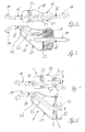
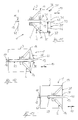
- a loudspeaker 2 is in one closed speaker housing 3 used.
- Speaker 2 is a cone speaker educated.
- Essential components of the loudspeaker 2 are a loudspeaker membrane 4 widened like a funnel, a loudspeaker basket 5 surrounding the loudspeaker membrane like a funnel and an annular magnet system.
- the magnet system has pole plates 6, 7, a ring magnet 8 lying between the pole plates 6, 7 and a pole core 9 radially surrounded by the ring magnet 8.
- the construction and the mode of operation of the loudspeaker 2 are generally known and are described, for example, in F. Hausdorf, Handbuch der loudspeaker technology, 3rd edition 1990, copyright VISATON, p. 22 ff .
- the pole plate 6 and the pole core 9 are centered in the axial direction 10 of the loudspeaker 2 pierced.
- a dust protection cap usually oriented transversely to the axial direction 10 in the area of the speaker diaphragm 2 is not available.
- the loudspeaker 2 can surround a sound tube 11 concentrically.
- the pole core lies here 9 directly on the tubular casing of the sound tube 11.
- the sound tube 11 penetrates form-fitting a recess 41 of the speaker cabinet 3 and serves Guidance of noise in the direction of sound guidance 12. The noise is then at the radiated as a radiation opening 13 effective tube mouth of the sound tube 11 to the outside.
- the speaker 2 is oriented relative to the sound tube 11 so that the radiation opening 13 and a the funnel opening of the speaker basket 5 delimiting Insert basket edge 14 approximately in the same plane. This will make them conventional Transmission paths between the radiation opening 13 and a loudspeaker largely avoided.
- the basket edge 14 is by a fastening means, not shown, on one Part of the loudspeaker housing 3 forming baffle 25 attached.
- the pole 9 can - as shown in FIG. 1 - contain several bores 15.
- the holes 15 are only indicated schematically.
- the holes 15 are together fluidly connected and also only schematically shown cooling lines 16 connected. This creates a closed cooling circuit, through which a suitable coolant flows to cool the magnet system is.
- the cooling circuit is either completely in the cavity 17 of the speaker cabinet 3 or the cooling lines 16 are connected to a suitable one Place out of the speaker cabinet 3 out.
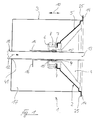
- a conventional silencer 18 in half-shell construction is shown in FIG. 2 and in FIG. 3 shown for exhaust pipes 19 in motor vehicles.
- the outer contour of the silencer 18 is adapted to the underbody of the motor vehicle.
- the silencer 18 consists of two half-shells 20, 21 which are connected by suitable connection techniques, e.g. Welding, are tightly connected to each other in a known manner.
- connection techniques e.g. Welding
- For mechanical Stabilization of the muffler 18 are located in the cavity thereof Support plates 22, 23 aligned perpendicular to the longitudinal axis of the exhaust pipe 19.
- Sound absorption is sound-absorbing damping material in the cavity of the silencer 18 24 inserted.
- the basic structure of the silencer 1 according to the invention can now advantageously be based on such a conventional silencer 18 are transmitted.
- This will be the Damping material 24 and the support plate 23 through the exhaust pipe concentrically surrounding speaker 2 replaced, and an opening in the half-shells 20,21 for created the speaker 2 for emitting the compensation sound, as in Fig. 4 and in Fig. 5 can be seen.
- the loudspeaker 2 has a dual function on the one hand, with its very stable speaker basket 5, the necessary mutual Support of the half-shells 20,21 for mechanical stabilization of the Muffler 18 and on the other hand, the radiation of the compensation sound Attenuation or cancellation of the exhaust noise.
- the conventional passive silencer 18 inexpensive and technically simple to the inventive active silencer 1 converted.
- One in Fig. 4 and in Fig. 5 not Cooling circuit shown for cooling the magnet system of the loudspeaker 2 can also be provided.
- the basket rim 14 is fastened to a baffle 25. It contains approximately one the cross section of the basket edge 14 corresponding recess for inserting the Loudspeaker 2 in the axial direction 10.
- the baffle 25, the basket edge 14 and the radiation opening 13 are approximately in the same plane. Closes the baffle 25 a room wall 26 on each side of the loudspeaker 2.
- the room walls 26 are only indicated schematically and can be self-contained.
- the baffle 25 and the room walls 26 close a room with the inside Noise. This can e.g. be a machine room.
- Via ventilation pipes or the like creates a connection to the outside that is permeable to noise. In this case the sound pipe 11 the ventilation duct with the radiation opening 13 as a ventilation opening outward.
- the noise emanating from a work or machine room is extinguished.
- the back of the loudspeaker 2 must be encapsulated.
- a housing-like encapsulation 42 is provided.
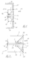
- the sound tube 11 is in the area of the loudspeaker 2 with a radial distance of surrounded an intermediate tube 27.
- the intermediate tube 27 extends in the axial direction 10 with its one pipe end beyond the pole plate 6 and ends with his other tube end at the radiation opening 13.
- the pole core 9 lies on the tube jacket of the Intermediate tube 27 immediately.
- the intermediate tube 27 consists of one for the thermal insulation of the speaker 2 from the sound tube 11 suitable Material. With the appropriate dimensioning of its dimensions, the intermediate tube acts 27 also in the manner of a bass reflex tube and thereby increases the efficiency of the silencer 1 when canceling the noise.
- the intermediate tube 27 with its radiation opening 13 is in the axial direction 10 opposite pipe end outside the speaker housing 3 out.
- pipe channel 28 is outside the loudspeaker housing 3 accessible.
- a suitable coolant such as e.g. Air or a fluid for cooling the speaker 2 can be introduced.
- the Pipe channel 28 of additional heat insulation between sound pipe 11 and loudspeaker 2 serve. 8 is the pipe channel 28 in the area of the magnet system of the speaker 2 filled by an insulating layer 29.
- the loudspeaker housing 3 in FIG. 9 filled with sound absorbing damping material 30.
- the damping material 30 covers the speaker diaphragm 4 in the axial direction 10 opposite Back wall of the speaker cabinet 3.
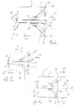
- the sound tube 11 is at its radiation opening 13 through an attachment tube 31 in Sound guidance direction 12 extended. It is either as a separate component at the radiation opening 13 attached or made in one piece with the sound tube 11.
- the inside diameter the sound tube 11 and the front tube 31 are approximately the same size.
- the tubular jacket of the front pipe 31 contains a variety of acoustically transparent Perforations 32.
- the acoustically transparent perforations 32 ensure at the same time the required superposition of the interference sound field and the compensation sound field according to the exemplary embodiments of the silencer 1 without the attachment pipe 31.
- a bundling tube 34 is also shown in FIG. 10. It closes at the front the speaker membrane 4 on the basket edge 14 and extends in the axial direction 10. Viewed in the axial direction 10, the bundling tube 34 is aligned with it Loudspeaker housing 3.
- the bundling tube 34 is either integral with the Loudspeaker housing 3 manufactured or as a separate component e.g. attached to the basket edge 14.
- the bundling tube 34 bundles the radiated from the speaker membrane 4 Compensation sound waves. This creates in the area in front of the radiation opening 13 a concentrated overlay zone between the interference sound field and the compensation sound field. There is therefore a larger proportion of that generated by the loudspeaker 2 Compensation sound field available for canceling the noise. The efficiency of the silencer 1 is further improved.
- the front of the speaker diaphragm 4 in the axial direction 10 is one plate-like, acoustically transparent perforated protective grille 35 covered. It is with Dashed line shown schematically.
- the protective grid 35 lies approximately in the plane the basket rim 14 a. It contains a central grating opening 36 for the radiation opening 13.
- the opposite end of the pipe edge 14 in the axial direction 10 of the Bundling tube 34 is connected to a further protective grid 35. Its lattice opening 36 radially surrounds the exhaust gas opening 33 of the attachment pipe 31 Tube of the bundling tube 34 connected protective grid 35 not only serves the mechanical damage protection of the speaker 2, but also that Protection of two control sensors attached to the inner wall of the bundling tube 34.
- the two control sensors are each a microphone 37. They take the canceled or damped noise and give an appropriate sensor signal to the control unit so that the loudspeaker 2 as a function of the sensor signal is controlled.
- the bundling tube 34 can on the inner wall the bundling tube 34 also other sensors or even a single sensor be attached.
- the microphone or are the microphones 37 with respect to a tube axis 43 of the Bundling tube 34 arranged at a radial distance which is 0.6 times the Pipe radius 44 of the bundling tube 34.
- the loudspeaker 2 is on its front side in the axial direction 10 of one Front chamber 38 covered like a hood.
- the attachment chamber 38 is a rotationally symmetrical one Component with the tube axis of the sound tube 11 as an imaginary axis of rotation. It is with its edge areas by fasteners, not shown fixed to the edge of the basket 14.
- the front chamber has 38 has a cross section which tapers conically in the axial direction 10.
- the conical taper opens into a pipe section 39.
- the sound tube 11 is in the direction of sound guidance 12 beyond the level of the basket rim 14 approximately up to the pipe section 39 extended. The latter delimits a chamber opening 40 and surrounds the sound tube 11 with radial distance.
- FIG. 13 shows a further exemplary embodiment of the front chamber 38.
- she is designed plate-like and lies plane-parallel to the plane of the basket rim 14.
- the plate-like attachment chamber 38 is drilled centrally.
- the hole is as a chamber opening 40 effective.
- a pipe section 39 protrudes from the front chamber 38 in the axial direction 10.
- the pipe section 39 the sound tube 11 and delimits the chamber opening 40.
- the front chamber 38 and the pipe section 39 act in the manner of a pressure chamber and thereby transform the compensation sound emitted by the loudspeaker 2, before it is overlaid with the noise in the area of the radiation opening 13.
- This transformation is the speaker diaphragm 4 better adapted to the air.
- the efficiency of the silencer 1 is further improved.
Landscapes
- Engineering & Computer Science (AREA)
- Physics & Mathematics (AREA)
- Acoustics & Sound (AREA)
- Multimedia (AREA)
- Chemical & Material Sciences (AREA)
- Combustion & Propulsion (AREA)
- Mechanical Engineering (AREA)
- General Engineering & Computer Science (AREA)
- Soundproofing, Sound Blocking, And Sound Damping (AREA)
- Exhaust Silencers (AREA)
Applications Claiming Priority (3)
| Application Number | Priority Date | Filing Date | Title |
|---|---|---|---|
| DE4322627 | 1993-07-07 | ||
| DE4322627 | 1993-07-07 | ||
| PCT/DE1994/000723 WO1995002238A1 (de) | 1993-07-07 | 1994-06-23 | Aktiver schalldämpfer |
Publications (2)
| Publication Number | Publication Date |
|---|---|
| EP0707737A1 EP0707737A1 (de) | 1996-04-24 |
| EP0707737B1 true EP0707737B1 (de) | 1998-11-04 |
Family
ID=6492183
Family Applications (1)
| Application Number | Title | Priority Date | Filing Date |
|---|---|---|---|
| EP94918733A Expired - Lifetime EP0707737B1 (de) | 1993-07-07 | 1994-06-23 | Aktiver schalldämpfer |
Country Status (12)
| Country | Link |
|---|---|
| US (1) | US5677958A (zh) |
| EP (1) | EP0707737B1 (zh) |
| JP (1) | JPH08512410A (zh) |
| KR (1) | KR960703256A (zh) |
| CN (1) | CN1064158C (zh) |
| AU (1) | AU6993794A (zh) |
| CA (1) | CA2166282A1 (zh) |
| CZ (1) | CZ284565B6 (zh) |
| DE (2) | DE59407238D1 (zh) |
| ES (1) | ES2126121T3 (zh) |
| PL (1) | PL173055B1 (zh) |
| WO (1) | WO1995002238A1 (zh) |
Families Citing this family (21)
| Publication number | Priority date | Publication date | Assignee | Title |
|---|---|---|---|---|
| FR2729781B1 (fr) * | 1995-01-23 | 1997-04-18 | Bertin & Cie | Dispositif de controle actif du bruit |
| DE19528888A1 (de) * | 1995-07-20 | 1997-01-23 | Nokia Deutschland Gmbh | Anordnung zur Auslöschung von Schallwellen |
| ATE225552T1 (de) * | 1995-07-20 | 2002-10-15 | Harman Audio Electronic Sys | Anordnung zur auslöschung von schallwellen |
| US5828759A (en) * | 1995-11-30 | 1998-10-27 | Siemens Electric Limited | System and method for reducing engine noise |
| JP2967400B2 (ja) * | 1995-12-15 | 1999-10-25 | 富士ゼロックス株式会社 | 画像形成装置の騒音マスキング装置および騒音マスキング方法 |
| FR2783870B1 (fr) * | 1998-09-24 | 2000-12-22 | Ecia Equip Composants Ind Auto | Systeme anti-bruit de ligne d'echappement pour vehicule automobile |
| FR2808161A1 (fr) * | 2000-04-19 | 2001-10-26 | Ecia Equip Composants Ind Auto | Haut-parleur et ligne d'echappement le comportant |
| DE102006010558A1 (de) * | 2006-03-06 | 2007-09-13 | J. Eberspächer GmbH & Co. KG | Aktiver Schalldämpfer für eine Abgasanlage |
| EP2071213B1 (en) * | 2007-12-11 | 2014-12-03 | General Electric Company | Gearbox noise reduction by electrical drive control |
| CN101231846B (zh) * | 2007-12-27 | 2011-02-02 | 中国农业大学 | 利用声波干涉方式的主动噪声控制系统及噪声控制方法 |
| DE102008018085A1 (de) * | 2008-04-09 | 2009-10-15 | J. Eberspächer GmbH & Co. KG | Aktiver Schalldämpfer |
| CN101691875B (zh) * | 2009-09-28 | 2011-07-20 | 浙江金盾风机风冷设备有限公司 | 地铁大型可逆风机用有源消声器 |
| JP5644593B2 (ja) * | 2011-03-07 | 2014-12-24 | ソニー株式会社 | スピーカー装置 |
| DE102012219981A1 (de) * | 2012-10-31 | 2014-06-12 | Bayerische Motoren Werke Aktiengesellschaft | Magnetkühlung für Aktoren einer aktiven Abgasanlage |
| KR101488323B1 (ko) * | 2013-08-20 | 2015-01-30 | 현대자동차주식회사 | 능동소음제어 스피커의 열해방지 구조 |
| CN103686565B (zh) * | 2013-12-29 | 2017-09-26 | 长城汽车股份有限公司 | 车内声音控制系统 |
| US9394812B2 (en) * | 2014-07-09 | 2016-07-19 | Aai Corporation | Attenuating engine noise using a reverse resonator |
| EP3249216B1 (en) * | 2016-05-27 | 2024-09-18 | Siemens Gamesa Renewable Energy A/S | Rotor blade with noise reduction means |
| CN108597489A (zh) * | 2018-04-21 | 2018-09-28 | 中车青岛四方机车车辆股份有限公司 | 一种高速列车车内噪声主动控制系统 |
| CN109253340B (zh) * | 2018-10-31 | 2024-04-19 | 中国船舶重工集团公司第七一九研究所 | 一种频率可调且可承压的共振式水消声器 |
| PL442352A1 (pl) * | 2022-09-24 | 2024-03-25 | Kfb Acoustics Spółka Z Ograniczoną Odpowiedzialnością | Tłumik pasywno-aktywny do redukcji hałasu w kanałach |
Family Cites Families (8)
| Publication number | Priority date | Publication date | Assignee | Title |
|---|---|---|---|---|
| US3936606A (en) * | 1971-12-07 | 1976-02-03 | Wanke Ronald L | Acoustic abatement method and apparatus |
| US5257316A (en) * | 1990-10-31 | 1993-10-26 | Matsushita Electric Works, Ltd. | Acoustic conductance and silencer utilizing same |
| AU542761B3 (en) * | 1985-01-16 | 1985-05-02 | Radovan Roy Zunic | Inner bass reflex |
| US4665549A (en) * | 1985-12-18 | 1987-05-12 | Nelson Industries Inc. | Hybrid active silencer |
| US5097923A (en) * | 1988-02-19 | 1992-03-24 | Noise Cancellation Technologies, Inc. | Active sound attenation system for engine exhaust systems and the like |
| BR8905996A (pt) * | 1988-02-19 | 1990-11-20 | Noise Cancellation Tech | Sistema de atenuacao de som ativo para sistemas de descarga de motor e semelhantes |
| AU7572191A (en) * | 1990-04-09 | 1991-10-30 | Active Noise And Vibration Technologies, Inc. | Single cavity automobile muffler |
| CA2112368C (en) * | 1992-05-01 | 1998-08-11 | Kazuhiro Sakiyama | Noise control device |
-
1994
- 1994-06-23 US US08/581,600 patent/US5677958A/en not_active Expired - Fee Related
- 1994-06-23 CZ CZ9619A patent/CZ284565B6/cs not_active IP Right Cessation
- 1994-06-23 KR KR1019950705702A patent/KR960703256A/ko not_active Application Discontinuation
- 1994-06-23 CA CA002166282A patent/CA2166282A1/en not_active Abandoned
- 1994-06-23 JP JP7503744A patent/JPH08512410A/ja active Pending
- 1994-06-23 DE DE59407238T patent/DE59407238D1/de not_active Expired - Fee Related
- 1994-06-23 DE DE4494827T patent/DE4494827D2/de not_active Expired - Fee Related
- 1994-06-23 PL PL94310994A patent/PL173055B1/pl unknown
- 1994-06-23 AU AU69937/94A patent/AU6993794A/en not_active Abandoned
- 1994-06-23 CN CN94192686A patent/CN1064158C/zh not_active Expired - Fee Related
- 1994-06-23 ES ES94918733T patent/ES2126121T3/es not_active Expired - Lifetime
- 1994-06-23 EP EP94918733A patent/EP0707737B1/de not_active Expired - Lifetime
- 1994-06-23 WO PCT/DE1994/000723 patent/WO1995002238A1/de active IP Right Grant
Also Published As
| Publication number | Publication date |
|---|---|
| AU6993794A (en) | 1995-02-06 |
| CZ1996A3 (en) | 1996-06-12 |
| US5677958A (en) | 1997-10-14 |
| CN1126525A (zh) | 1996-07-10 |
| PL173055B1 (pl) | 1998-01-30 |
| CN1064158C (zh) | 2001-04-04 |
| CA2166282A1 (en) | 1995-01-19 |
| DE4494827D2 (de) | 1996-08-22 |
| KR960703256A (ko) | 1996-06-19 |
| EP0707737A1 (de) | 1996-04-24 |
| CZ284565B6 (cs) | 1999-01-13 |
| JPH08512410A (ja) | 1996-12-24 |
| ES2126121T3 (es) | 1999-03-16 |
| WO1995002238A1 (de) | 1995-01-19 |
| DE59407238D1 (de) | 1998-12-10 |
| PL310994A1 (en) | 1996-01-22 |
Similar Documents
| Publication | Publication Date | Title |
|---|---|---|
| EP0707737B1 (de) | Aktiver schalldämpfer | |
| DE69310174T2 (de) | Wandleranordnung für aktivschallunterdrükungssysteme | |
| EP2623737B1 (de) | Aktiver Schalldämpfer | |
| JP4659021B2 (ja) | ターボファンエンジン内の騒音低減構造 | |
| US4381832A (en) | Exhaust silencer having an incorporated resonator for an internal combustion engine | |
| DE102009049280B4 (de) | Aktiver Schalldämpfer | |
| DE102011089772B4 (de) | Abgasanlage | |
| EP1898059A2 (de) | Aktiver Schalldämpfer für eine Abgasanlage | |
| DE4342133A1 (de) | Anordnung zur aktiven Schalldämpfung | |
| EP2607640B1 (de) | Aktoranordnung für aktive Abgasanlagen und Verfahren zum Betreiben derselben | |
| EP2884063A2 (de) | Schallerzeuger für ein system zur beeinflussung von abgasgeräuschen eines kraftfahrzeugs | |
| EP1832725A2 (de) | Aktiver Schalldämpfer für eine Abgasanlage | |
| WO2019121744A1 (de) | Breitbanddämpfer für einen kraftfahrzeug-motor | |
| EP2607639B1 (de) | Abgasanlage | |
| US20070045041A1 (en) | Muffler for an exhaust system | |
| DE2547523A1 (de) | Brennkraftmaschine mit geraeuschdaempfender verschalung | |
| DE102008007967B4 (de) | Brennstoffbetriebenes Fahrzeugheizgerät und Abgasführungssystem bei einem brennstoffbetriebenen Fahrzeugheizgerät | |
| JPH06147624A (ja) | 送風ダクトの消音ボックス | |
| JP3508337B2 (ja) | 放射音低減装置 | |
| JPH09236008A (ja) | 自動車用排気消音装置 | |
| JP3185447B2 (ja) | 能動的ダクト消音装置 | |
| JPH0435530Y2 (zh) | ||
| WO2000032910A1 (en) | Noise suppressing device | |
| KR20210037446A (ko) | 저소음튜닝머플러장치 | |
| KR19990010289U (ko) | 자동차 머플러의 흡음구조 |
Legal Events
| Date | Code | Title | Description |
|---|---|---|---|
| PUAI | Public reference made under article 153(3) epc to a published international application that has entered the european phase |
Free format text: ORIGINAL CODE: 0009012 |
|
| 17P | Request for examination filed |
Effective date: 19950907 |
|
| AK | Designated contracting states |
Kind code of ref document: A1 Designated state(s): BE DE ES FR GB IT NL PT SE |
|
| GRAG | Despatch of communication of intention to grant |
Free format text: ORIGINAL CODE: EPIDOS AGRA |
|
| 17Q | First examination report despatched |
Effective date: 19971223 |
|
| GRAG | Despatch of communication of intention to grant |
Free format text: ORIGINAL CODE: EPIDOS AGRA |
|
| GRAH | Despatch of communication of intention to grant a patent |
Free format text: ORIGINAL CODE: EPIDOS IGRA |
|
| GRAH | Despatch of communication of intention to grant a patent |
Free format text: ORIGINAL CODE: EPIDOS IGRA |
|
| GRAA | (expected) grant |
Free format text: ORIGINAL CODE: 0009210 |
|
| AK | Designated contracting states |
Kind code of ref document: B1 Designated state(s): BE DE ES FR GB IT NL PT SE |
|
| PG25 | Lapsed in a contracting state [announced via postgrant information from national office to epo] |
Ref country code: NL Free format text: LAPSE BECAUSE OF FAILURE TO SUBMIT A TRANSLATION OF THE DESCRIPTION OR TO PAY THE FEE WITHIN THE PRESCRIBED TIME-LIMIT Effective date: 19981104 |
|
| REF | Corresponds to: |
Ref document number: 59407238 Country of ref document: DE Date of ref document: 19981210 |
|
| ITF | It: translation for a ep patent filed | ||
| PG25 | Lapsed in a contracting state [announced via postgrant information from national office to epo] |
Ref country code: PT Free format text: LAPSE BECAUSE OF FAILURE TO SUBMIT A TRANSLATION OF THE DESCRIPTION OR TO PAY THE FEE WITHIN THE PRESCRIBED TIME-LIMIT Effective date: 19990204 |
|
| GBT | Gb: translation of ep patent filed (gb section 77(6)(a)/1977) |
Effective date: 19990202 |
|
| ET | Fr: translation filed | ||
| REG | Reference to a national code |
Ref country code: ES Ref legal event code: FG2A Ref document number: 2126121 Country of ref document: ES Kind code of ref document: T3 |
|
| NLV1 | Nl: lapsed or annulled due to failure to fulfill the requirements of art. 29p and 29m of the patents act | ||
| PG25 | Lapsed in a contracting state [announced via postgrant information from national office to epo] |
Ref country code: BE Free format text: LAPSE BECAUSE OF NON-PAYMENT OF DUE FEES Effective date: 19990630 |
|
| PLBE | No opposition filed within time limit |
Free format text: ORIGINAL CODE: 0009261 |
|
| STAA | Information on the status of an ep patent application or granted ep patent |
Free format text: STATUS: NO OPPOSITION FILED WITHIN TIME LIMIT |
|
| 26N | No opposition filed | ||
| BERE | Be: lapsed |
Owner name: LEISTRITZ A.G. & CO. ABGASTECHNIK Effective date: 19990630 |
|
| REG | Reference to a national code |
Ref country code: GB Ref legal event code: IF02 |
|
| PGFP | Annual fee paid to national office [announced via postgrant information from national office to epo] |
Ref country code: FR Payment date: 20020617 Year of fee payment: 9 |
|
| PGFP | Annual fee paid to national office [announced via postgrant information from national office to epo] |
Ref country code: SE Payment date: 20020624 Year of fee payment: 9 |
|
| PGFP | Annual fee paid to national office [announced via postgrant information from national office to epo] |
Ref country code: ES Payment date: 20020625 Year of fee payment: 9 |
|
| PGFP | Annual fee paid to national office [announced via postgrant information from national office to epo] |
Ref country code: GB Payment date: 20030530 Year of fee payment: 10 |
|
| PG25 | Lapsed in a contracting state [announced via postgrant information from national office to epo] |
Ref country code: SE Free format text: LAPSE BECAUSE OF NON-PAYMENT OF DUE FEES Effective date: 20030624 Ref country code: ES Free format text: LAPSE BECAUSE OF NON-PAYMENT OF DUE FEES Effective date: 20030624 |
|
| EUG | Se: european patent has lapsed | ||
| PG25 | Lapsed in a contracting state [announced via postgrant information from national office to epo] |
Ref country code: FR Free format text: LAPSE BECAUSE OF NON-PAYMENT OF DUE FEES Effective date: 20040227 |
|
| REG | Reference to a national code |
Ref country code: FR Ref legal event code: ST |
|
| PG25 | Lapsed in a contracting state [announced via postgrant information from national office to epo] |
Ref country code: GB Free format text: LAPSE BECAUSE OF NON-PAYMENT OF DUE FEES Effective date: 20040623 |
|
| REG | Reference to a national code |
Ref country code: ES Ref legal event code: FD2A Effective date: 20030624 |
|
| GBPC | Gb: european patent ceased through non-payment of renewal fee |
Effective date: 20040623 |
|
| PG25 | Lapsed in a contracting state [announced via postgrant information from national office to epo] |
Ref country code: IT Free format text: LAPSE BECAUSE OF NON-PAYMENT OF DUE FEES;WARNING: LAPSES OF ITALIAN PATENTS WITH EFFECTIVE DATE BEFORE 2007 MAY HAVE OCCURRED AT ANY TIME BEFORE 2007. THE CORRECT EFFECTIVE DATE MAY BE DIFFERENT FROM THE ONE RECORDED. Effective date: 20050623 |
|
| PGFP | Annual fee paid to national office [announced via postgrant information from national office to epo] |
Ref country code: DE Payment date: 20070626 Year of fee payment: 14 |
|
| PG25 | Lapsed in a contracting state [announced via postgrant information from national office to epo] |
Ref country code: DE Free format text: LAPSE BECAUSE OF NON-PAYMENT OF DUE FEES Effective date: 20090101 |