EP0706769A2 - Working height adjustment device for a table desktop or the like - Google Patents
Working height adjustment device for a table desktop or the like Download PDFInfo
- Publication number
- EP0706769A2 EP0706769A2 EP95116005A EP95116005A EP0706769A2 EP 0706769 A2 EP0706769 A2 EP 0706769A2 EP 95116005 A EP95116005 A EP 95116005A EP 95116005 A EP95116005 A EP 95116005A EP 0706769 A2 EP0706769 A2 EP 0706769A2
- Authority
- EP
- European Patent Office
- Prior art keywords
- table top
- support frame
- parallel
- spring
- parallel link
- Prior art date
- Legal status (The legal status is an assumption and is not a legal conclusion. Google has not performed a legal analysis and makes no representation as to the accuracy of the status listed.)
- Withdrawn
Links
Images


Classifications
-
- A—HUMAN NECESSITIES
- A47—FURNITURE; DOMESTIC ARTICLES OR APPLIANCES; COFFEE MILLS; SPICE MILLS; SUCTION CLEANERS IN GENERAL
- A47B—TABLES; DESKS; OFFICE FURNITURE; CABINETS; DRAWERS; GENERAL DETAILS OF FURNITURE
- A47B9/00—Tables with tops of variable height
-
- A—HUMAN NECESSITIES
- A47—FURNITURE; DOMESTIC ARTICLES OR APPLIANCES; COFFEE MILLS; SPICE MILLS; SUCTION CLEANERS IN GENERAL
- A47B—TABLES; DESKS; OFFICE FURNITURE; CABINETS; DRAWERS; GENERAL DETAILS OF FURNITURE
- A47B2200/00—General construction of tables or desks
- A47B2200/0035—Tables or desks with features relating to adjustability or folding
- A47B2200/005—Leg adjustment
- A47B2200/0056—Leg adjustment with a motor, e.g. an electric motor
Landscapes
- Machine Tool Units (AREA)
- Workshop Equipment, Work Benches, Supports, Or Storage Means (AREA)
Abstract
Description
Die Erfindung betrifft eine Vorrichtung zum Verstellen der Arbeitshöhe einer Tischplatte oder dergleichen gegenüber einem Traggestell mit Höhenarretiermitteln und Parallelenkerführungen, die je zwei Parallellenker aufweisen und zwischen dem Traggestell und der Tischplatte oder dergleichen angeordnet sind.The invention relates to a device for adjusting the working height of a table top or the like compared to a support frame with height locking means and parallel link guides, each having two parallel links and are arranged between the support frame and the table top or the like.
Für solche Vorrichtungen ist bereits eine Vielzahl von Losungen vorgeschlagen worden, die alle die an sie gestellten Forderungen weitgehend erfüllen, um die Arbeitshöhe einer Tischplatte oder dergleichen den Bedürfnissen anzupassen. Hierbei gibt es Verstellvorrichtungen, die verhältnismäßig einfach aufgebaut sind, aber nur eine Justage beim Aufstellen zulassen, da die Verstellung verhältnismäßig umständlich erfolgt. Andere Vorrichtungen, die durch den Benutzer jederzeit eine feinfühlige Verstellung ermöglichen, sind verhältnismäßig kompliziert und aufwendig aufgebaut. Soll eine Arbeits- oder Tischplatte sowohl für eine Sitzposition als auch für eine Stehposition eingerichtet sein, so ist ein verhältnismäßig großer Verstellbereich, z.B. über 500 mm Höhenverstellung, erforderlich. Auf dem Gebiet der Zeichenbretter sind z.B. Verstellvorrichtungen bekannt, die eine Anpassung sowohl an die Sitzposition als auch an die Stehposition zulassen und mit Parallelogrammlenkerführungen arbeiten. Außerdem weisen solche Vorrichtungen auch Arretiermittel auf, um die jeweilige eingestellte Position zu fixieren. Der Nachteil solcher bekannter Verstellvorrichtungen ist meist jedoch, daß die Arbeitsplatte gegenüber einem Traggestell je nach der Höheneinstellung wandert, so daß hinter einem solchen Zeichenbrett genügend Reserveraum vorhanden sein muß (siehe z.B. DE-GM 76 40 895).A large number of solutions have already been proposed for such devices, all of which largely meet the requirements placed on them in order to adapt the working height of a table top or the like to needs. There are adjustment devices that are relatively simple in construction, but only allow adjustment when setting up, since the adjustment is relatively cumbersome. Other devices that enable the user to make sensitive adjustments at any time are relatively complicated and complex. If a worktop or table top is to be set up for both a sitting position and a standing position, a relatively large adjustment range, for example over 500 mm height adjustment, is required. In the field of drawing boards, for example, adjustment devices are known which allow adaptation to both the sitting position and the standing position and which work with parallelogram link guides. Such devices also have locking means to fix the respective set position. The disadvantage of such known adjustment devices is usually, however, that the worktop moves relative to a support frame depending on the height setting, so that behind such a drawing board enough reserve space must be available (see for example DE-GM 76 40 895).
Der vorliegenden Erfindung liegt die Aufgabe zugrunde, eine Vorrichtung zum Verstellen der Arbeitshöhe einer Tischplatte oder dergleichen vorzuschlagen, die einen großen Höhenverstellbereich zuläßt, bei der die Höhenverstellung und anschließende Arretierung auf einfache Weise schnell erfolgen kann, und bei der auch kein Wandern der Tischplatte oder dergleichen gegenüber dem Traggestell in der Plattenebene bei der Verstellung erfolgt.The present invention has for its object to provide a device for adjusting the working height of a table top or the like, which allows a large height adjustment range, in which the height adjustment and subsequent locking can be done quickly and easily, and in which no walking of the table top or the like compared to the support frame in the plate level during the adjustment.
Diese Aufgabe wird gemäß der vorliegenden Erfindung bei einer Vorrichtung zum Verstellen der Arbeitshöhe mit zwei Parallellenkern der eingangs genannten Art dadurch gelöst, daß die beiden Parallellenker einerseits an zwei beabstandeten, festen Anlenkpunkten am Traggestell und andererseits an zwei beabstandeten Anlenkpunkten eines unter der Tischplatte parallel zur Ebene der Tischplatte verschiebbar geführten Führungselementes angelenkt sind, wobei der Abstand zwischen den Anlenkpunkten kleiner als die Länge der Parallellenker ist, und daß zur Fixierung der Position der Tischplatte in der waagerechten Ebene gegenüber dem Traggestell zwischen der Mitte eines der Parallellenker und einem festen Punkt an der Tischplatte ein Koppellenker angeordnet ist.This object is achieved according to the present invention in a device for adjusting the working height with two parallel linkages of the type mentioned in that the two parallel links on the one hand at two spaced, fixed articulation points on the support frame and on the other hand at two spaced articulation points one below the table top parallel to the plane the table top slidably guided guide element, the distance between the articulation points is smaller than the length of the parallel link, and that to fix the position of the table top in the horizontal plane relative to the support frame between the center of one of the parallel links and a fixed point on the table top a coupling link is arranged.
Die erfindungsgemäße Lösung hat den großen Vorteil, daß nicht nur die gestellte Aufgabe vollends erfüllt wird, sondern daß darüber hinaus ihr Aufbau einfach und kostensparend ist, und darüber hinaus auf einfache Weise eine Ausbalancierung des Gewichtes der Tischplatte oder dergleichen, einschließlich daraufstehenden Gegenständen oder Geräten möglich ist.The solution according to the invention has the great advantage that not only the task is fully accomplished, but that its structure is simple and cost-saving, and moreover, in a simple manner, a balance of the weight of the table top or the like, including objects or devices standing thereon possible is.
In einer vorteilhaften und stabilen Ausführungsform sind vorzugsweise zwei Parallellenkerführungen im seitlichen Abstand voneinander zwischen dem Traggestell und der Tischplatte oder dergleichen vorgesehen. Die einander entsprechenden Parallellenker und Führungselemente der beiden Parallellenkerführungen sind dabei zweckmäßigerweise durch Traversen miteinander verbunden, um die Stabilität und Verkantungen zu vermeiden.In an advantageous and stable embodiment, two parallel link guides are preferably provided at a lateral distance from one another between the support frame and the table top or the like. The mutually corresponding parallel link and guide elements of the two parallel link guides are expediently connected to one another by traverses in order to avoid stability and tilting.
Zum Gewichtsausgleich ist, pro Parallellenkerführung, eine Ausgleichszugfeder zwischen den Anlenkpunkten der Parallellenker derart vorgesehen, daß die Federkraft in Anheberichtung der Tischplatte oder dergleichen wirkt. Vorzugsweise ist die Ausgleichszugfeder nur für den Gewichtsausgleich der Tischplatte oder dergleichen ausgelegt, während zum weiteren Gewichtsausgleich von auf der Tischplatte ruhenden Gegenständen, Geräten oder dergleichen im Bereich der Anlenkpunkte der Parallellenker am Traggestell, also im Bereich der unteren Anlenkpunkte, eine Schenkelfeder vorgesehen ist. Sowohl die Ausgleichszugfeder als auch die Schenkelfeder sind vorzugsweise einstellbar ausgebildet, um zum einen eine Anfangsgrundstellung einzustellen und zum anderen den verschiedenen Belastungssituationen der Tischplatte oder dergleichen Rechnung zu tragen.To balance the weight, a compensating tension spring is provided between the articulation points of the parallel link for each parallel link guide in such a way that the spring force acts in the lifting direction of the table top or the like. The compensating tension spring is preferably only designed for the weight compensation of the table top or the like, while a leg spring is provided for further weight compensation of objects, devices or the like resting on the table top in the region of the articulation points of the parallel links on the support frame, that is to say in the region of the lower articulation points. Both the compensating tension spring and the leg spring are preferably designed to be adjustable, on the one hand to set an initial basic position and, on the other hand, to take into account the different loading situations of the table top or the like.
Die Höhenarretiermittel für die erfindungsgemäße Vorrichtung sind vorzugsweise als Lamellenbremse ausgebildet, die die Parallellenker im Bereich der oberen Anlenkpunkte verriegeln. Dies erfolgt vorzugsweise dadurch, daß die Lamellenbremse zwischen dem Führungselement und einem der Parallellenker angreifen.The height locking means for the device according to the invention are preferably designed as multi-disk brakes which lock the parallel links in the area of the upper articulation points. This is preferably done in that the multi-disc brake acts between the guide element and one of the parallel links.
Die vorstehend erwähnte Gewichtsausgleichsanordnung zum Ausgleich des Leergewichts der Tischplatte bzw. zum Ausgleich von darauf abgestellten Gegenständen läßt einen Gewichtsausgleich nur in gewissen Grenzen zu. Weitere Ungleichgewichte werden meist nur über die Höhenarretiervorrichtung abgebremst, damit die Tischplatte bei Gewichtsveränderungen nicht nach oben oder unten ausweicht. Eine besonders vorteilhafte Gewichtsausgleichsvorrichtung, die über einen weiten Bereich einen feinfühligen, weitgehend vollständigen Gewichtsausgleich zuläßt, ist gemäß einer vorteilhaften Ausführungsform gekennzeichnet durch eine in dem Traggestell quer zwischen den beiden Parallellenkerführungen angeordnete, gemeinsame Ausgleichsfederanordnung, die mit ihren beiden Enden an je einem Diagonalpunkt der Parallellenkerführungen angreift. Diese Lösung hat den wesentlichen Vorteil, daß bei einer Vorrichtung mit an einem Traggestell beiderseits angeordneten Parallellenkerführungen nur eine einzige Ausgleichsfederanordnung notwendig ist, für die genügend Raum vorhanden ist, um auch große Federkräfte über einen großen Federhub zu erzielen, denn die Queranordnung im Traggestell läßt eine Unterbringung zu, bei der auch eine großvolumige Ausgleichsfeder nicht stört.The above-mentioned weight balancing arrangement for balancing the empty weight of the table top or for balancing objects placed thereon allows weight balancing only within certain limits. Further imbalances are usually only braked using the height locking device so that the table top does not move up or down when the weight changes. A particularly advantageous weight balancing device, which allows sensitive, largely complete weight balancing over a wide range, is characterized according to an advantageous embodiment by a common balancing spring arrangement arranged transversely between the two parallel link guides in the supporting frame, with its two ends at a diagonal point of the parallel link guides attacks. This solution has the essential advantage that in a device with parallel link guides arranged on both sides of a support frame, only a single compensating spring arrangement is necessary, for which there is enough space to achieve large spring forces over a large spring stroke, because the transverse arrangement in the support frame allows one Accommodation in which a large-volume compensation spring does not interfere.
Um den Verstellmechanismus für die Tischplatte oder dergleichen vielen verschiedenen Belastungen anpassen zu können, ist die Federkraft der Ausgleichsfederanordnung vorzugsweise einstellbar. Hierdurch ist es möglich, einen Gewichtsausgleich z.B. bei unbelasteter Tischplatte oder bei geringere Belastung durchzuführen. Andererseits ist es jedoch auch möglich, das Gewicht von sehr schweren, auf der Tischplatte abgestellten Geräten auszugleichen, z.B. von Geräten mit einem Gewicht von 50 - 80 kg.In order to be able to adapt the adjustment mechanism for the table top or the like to many different loads, the spring force of the compensating spring arrangement is preferably adjustable. This makes it possible to get one Weight compensation, for example, when the table top is unloaded or when the load is less. On the other hand, it is also possible to balance the weight of very heavy devices placed on the table top, for example devices with a weight of 50-80 kg.
Die Kraftübertragung zwischen der Ausgleichsfederanordnung zu den Parallellenkerführungen erfolgt in einer vorteilhaften Ausführungsform über Zugseile, wodurch es möglich ist, die Federkräfte genau in der Diagonalen der Parallelenkerführungen angreifen zu lassen. Besonders kompakte Verhältnisse für die Ausgleichsfederanordnung ergeben sich dann, wenn diese eine Druckfeder enthält, deren Enden sich an linear geführten Gleitelementen abstützen, wobei die Zugseile überkreuzend mit den Gleitelementen gekoppelt sind. Bei einer solchen Lösung ist eine Verstellbarkeit der Federkraft besonders einfach auszuführen, indem ein ebenfalls linear geführtes Verstellelement vorgesehen ist, dessen Abstand von einem der Gleitelemente durch eine Spindel verstellbar ist und das mit einem der beiden Zugseile verbunden ist, während das andere Zugseil mit dem anderen Gleitelement verbunden ist.In an advantageous embodiment, the force transmission between the compensating spring arrangement to the parallel link guides takes place via traction cables, which makes it possible to have the spring forces act exactly in the diagonal of the parallel link guides. Particularly compact conditions for the compensating spring arrangement result if it contains a compression spring, the ends of which are supported on linearly guided sliding elements, the traction cables being cross-coupled to the sliding elements. In such a solution, an adjustability of the spring force is particularly simple to carry out by providing a likewise linearly guided adjusting element whose distance from one of the sliding elements can be adjusted by a spindle and which is connected to one of the two pulling cables while the other pulling cable is connected to the other Sliding element is connected.
Während die vorstehenden Ausführungen eine Schnellverstellung durch Lösen der Höhenarretiervorrichtung und Anheben und Absenken der Tischplatte per Hand zulassen, wobei das Gewicht der Tischplatte sowie gegebenenfalls des darauf abgestellten Gegenstandes durch eine Gewichtsausgleichsvorrichtung weitgehend ausgeglichen ist, so ist es gemäß einer weiteren vorteilhaften Ausführungsform der vorliegenden Erfindung auch möglich, die Verstellung und Höhenarretierung durch einen Spindelantrieb vorzunehmen, der entweder per Hand mittels einer Kurbel oder durch einen Elektromotor mit Untersetzungsgetriebe betätigt wird. Eine solche vorteilhafte Ausführungsform ist gekennzeichnet durch einen zwischen der Tischplatte und dem Führungselement angeordneten Spindelantrieb als Höhenarretiermittel. Zweckmäßigerweise besteht der Spindelantrieb aus einer Gewindespindel und einer Gewindebuchse, wobei die Gewindespindel an einer mit der Tischplatte verbundenen Führungsschiene in Längsrichtung unverschiebbar gelagert ist, während die Gewindebuchse mit dem Führungselement gekoppelt ist.While the above explanations allow a quick adjustment by releasing the height locking device and lifting and lowering the table top by hand, the weight of the table top and possibly the object placed thereon being largely balanced by a weight balancing device, it is also according to a further advantageous embodiment of the present invention possible to make the adjustment and height lock by a spindle drive, which is operated either by hand using a crank or by an electric motor with reduction gear. Such an advantageous embodiment is characterized by a spindle drive arranged between the table top and the guide element as height locking means. The spindle drive expediently consists of a threaded spindle and a threaded bushing, the threaded spindle being mounted non-displaceably in the longitudinal direction on a guide rail connected to the table top, while the threaded bushing is coupled to the guide element.
Eine weitere Ausführungsform enthält einen in der Diagonalen zwischen zwei Anlenkpunkten der Parallellenker angreifenden Spindelantrieb mit Elektromotor.A further embodiment contains a spindle drive with an electric motor acting in the diagonal between two articulation points of the parallel links.
Da ein solcher Spindelantrieb selbsthemmend ausgebildet werden kann, dient dieser Spindelantrieb gleichzeitig als Höhenarretiervorrichtung, wobei ein Gewichtsausgleich meist entfallen kann.Since such a spindle drive can be designed to be self-locking, this spindle drive serves at the same time as a height locking device, and weight compensation can usually be dispensed with.
Weitere vorteilhafte Ausgestaltungen sind im einzelnen den Unteransprüchen zu entnehmen.Further advantageous refinements can be found in the dependent claims.
Die Erfindung wird nachfolgend anhand eines Ausführungsbeispiels unter Bezug auf die beigefügten Zeichnungen näher erläutert.The invention is explained in more detail below using an exemplary embodiment with reference to the accompanying drawings.
Es zeigen:
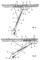
- Fig. 1a + 1b
- schematische Darstellungen einer Parallellenkerführung der erfindungsgemäßen Verstellvorrichtung in zwei verschiedenen Höhenpositionen und schematischer Darstellung;
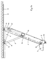
- Fig. 2a + 2b
- ähnliche Ansichten wie Fig. 1a und 1b, jedoch in einer bevorzugten konstruktiven Ausführung;
- Fig. 3
- eine Frontansicht der Vorrichtung nach den Fig. 2a und 2b;
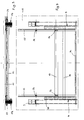
- Fig. 4
- eine Draufsicht auf die Vorrichtung nach den Fig. 2a, 2b und 3, wobei die Tischplatte nur strichpunktiert angedeutet ist;
- Fig. 5
- eine Detaildarstellung der Höhenarretiermittel, wie sie in Fig. 3 zu sehen sind;
- Fig. 6
- eine Ausschnittsdarstellung der Verstellvorrichtung mit einer Vorrichtung zum Gewichtsausgleich;
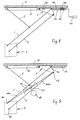
- Fig. 7
- eine gemeinsame Ausgleichsfederanordnung für beide Seiten der Verstellvorrichtung; und
- Fig. 8 + 9
- zwei weitere Ausführungsformen mit einem Spindelantrieb als Höhenarretiermittel.
- 1a + 1b
- schematic representations of a parallel link guide of the adjusting device according to the invention in two different height positions and a schematic representation;
- 2a + 2b
- Similar views as Figures 1a and 1b, but in a preferred constructional embodiment.
- Fig. 3
- a front view of the device of Figures 2a and 2b.
- Fig. 4
- a plan view of the device of Figures 2a, 2b and 3, wherein the table top is only indicated by dash-dotted lines.
- Fig. 5
- a detailed view of the height locking means, as can be seen in Fig. 3;
- Fig. 6
- a sectional view of the adjustment device with a device for weight compensation;
- Fig. 7
- a common balance spring arrangement for both sides of the adjusting device; and
- Fig. 8 + 9
- two further embodiments with a spindle drive as height locking means.
Anhand der Fig. 1a und 1b soll nun der funktionelle Aufbau der erfindungsgemäßen Vorrichtung zum Verstellen der Arbeitshöhe einer Tischplatte oder dergleichen erfolgen, da die mehr konstruktive Details zeigenden Fig. 2a und 2b etwas unübersichtlicher sind.1a and 1b, the functional structure of the device according to the invention for adjusting the working height of a table top or the like is now to be carried out, since FIGS. 2a and 2b, which show more structural details, are somewhat more confusing.
Eine Tischplatte 11 oder dergleichen soll gegenüber einem Traggestell 3 zwischen einer niedrigen Höhe (Fig. 1b) und einer ausgefahrenen Position (Fig. 1a) stufenlos verstellt werden. Fig. 1b entspricht hierbei noch nicht der unteren Endposition, sondern diese ist in Fig. 2b gezeigt.A
Am Traggestell 3 sind zwei feste Anlenkpunkte bzw. Anlenkachsen 6a und 6b im Abstand voneinander angeordnet, und diese Anlenkpunkte 6a und 6b sind über Parallellenker 1 und 2 mit zwei weiteren Anlenkpunkten 6c und 6d gekoppelt. Die oberen Anlenkpunkte 6c und 6d sind auf einem Schenkel 4a eines Führungselementes 4 angeordnet, das gegenüber der Tischplatte 11 in der Plattenebene parallel verschiebbar geführt ist. Die Parallelführung erfolgt mittels an einem Halter 4b angeordneten Gleitstücken 4c in einer Z-förmigen Führungsschiene 12. Würde man das Führungselement 4 fest mit der Tischplatte 11 verbinden, so würde die Tischplatte 11 bei einer Veränderung der Höhe durch die Parallellenkerführung zwar parallel geführt, jedoch in der Plattenebene gegenüber dem Traggestell 3 verschoben, was unerwünscht wäre. Um die Tischplatte gegenüber dem Traggestell 3 in immer der gleichen Position bei jeder Höheneinstellung zu halten, ist ein Koppellenker 5 vorgesehen, der mit einem Ende an einem festen Anlenkpunkt 5a an der Tischplatte 11 und mit seinem anderen Ende mit der Mitte 5b des Parallellenkers 1 gekoppelt ist. Zwischen den Anlenkpunkten 5a, 5b und 6a wird ein erstes gleichschenkliges Dreieck gebildet, während zwischen den Anlenkpunkten 5a, 5b und 6c ein zweites gleichschenkliges Dreieck gebildet wird, wodurch sichergestellt wird, daß bei einer Verschiebemöglichkeit des Anlenkpunktes 6a gegenüber der Tischplatte 11 der Anlenkpunkt 5a und damit die Tischplatte 11 immer die gleiche Position gegenüber dem Traggestell 3 in der Plattenebene einnimmt.Two fixed articulation points or
Um einen Gewichtsausgleich für die Belastung der Tischplatte 11 zu ermöglichen, ist zwischen den Anlenkpunkten 6a und 6d eine Ausgleichszugfeder 21 vorgesehen. Die Zugkraft dieser Ausgleichszugfeder 21 ist einstellbar, um entweder den Ausgleich für eine leere Tischplatte 11 einzustellen oder noch zusätzliche Last auf der Tischplatte 11 zu berücksichtigen. In Fig. 1 ist zusätzlich zur Ausgleichszugfeder 21 eine Schenkelfeder 22 im Bereich des Anlenkpunktes 6b angedeutet, mit der zweckmäßigerweise die Belastung der Tischplatte 11 einstellbar ausgeglichen wird.In order to enable weight compensation for the load on the
In den Fig. 1a und 1b ist außerdem ein Spannhebel 15 angedeutet, mit der eine Arretiervorrichtung für die Verstellvorrichtung betätigt werden kann, um in jeder eingestellten Höhe der Tischplatte 11 die Stellung festzusetzen. Der detaillierte Aufbau der Arretiervorrichtung wird später noch im einzelnen erläutert.In FIGS. 1a and 1b, a clamping
Aus den Fig. 2a, 2b, 3 und 4 gehen nun weitere Details des konstruktiven Aufbaus der erfindungsgemäßen Vorrichtung hervor. Das mit dem Bezugszeichen 3 angedeutete Traggestell besteht im vorliegenden Fall aus einem Haltewinkel 3a, mit dem die gesamte Vorrichtung einschließlich Parallellenkerführungen und Höhenarretierungsmitteln und aufgesetzter Tischplatte 11 an einem Tischuntergestell oder dergleichen bzw. einem Querträger 10 eines solchen Tischgestells befestigt werden kann. Fig. 2a zeigt, daß die Bauhöhe der Verstellvorrichtung außerordentlich gering ist, und daß die Tischplatte aus dieser niedrigen Stellung in die oberste Stellung (siehe Fig. 2a) ausgefahren werden kann. Der gesamte Parallellenkermechanismus ist als eine weitgehend geschlossene Einheit aufgebaut, d.h., die beiden Parallellenker 1 und 2, die nur einen verhältnismäßig geringen Abstand voneinander haben, sind als U-förmige Profile ausgebildet (siehe hierzu insbesondere die Detaildarstellung in Fig. 5), wobei beide mit verschiedener Schenkelbreite ausgebildet sind, und der Parallellenker 2 auf diese Weise als innen angeordneter Parallellenker in den außen angeordneten Parallellenker 1 eingreift. In der oberen Endstellung (siehe Fig. 2a) greifen die beiden Parallellenker 1 und 2 voll ineinander, während sie sich in der unteren Endstellung (Fig. 2b) immer noch überlappen.2a, 2b, 3 and 4 now further details of the structural design of the device according to the invention. That indicated with the
Die Parallellenker 1 und 2 der jeweils nebeneinander liegenden Parallellenkerführungen des Gesamtmechanismus sind durch eine Quertraverse 13 miteinander verbunden, damit beim Verstellen keine Verkantungen auftreten. Darüber hinaus sind die Führungselemente 4 durch eine Quertraverse 14 ebenfalls miteinander verbunden. Wie aus den Fig. 3 und 4 und insbesondere aus der Detaildarstellung nach Fig. 5 zu sehen ist, sind die Führungselemente 4 auf beiden Seiten als U-Profile ausgebildet, um eine stabile Halterung der Anlenkpunkte 6c und 6d zu gewährleisten. Zur Parallelführung in den Führungsschienen 12 sind Halter 4b befestigt, die an ihren Enden Gleitstücke 4c tragen (siehe auch Fig. 1a und 1b). Diese Gleitstücke 4c greifen in den offenen Bereich der Z-förmigen Führungsschienen 12 ein, die wiederum an einem entsprechenden Träger befestigt sind, auf dem die Tischplatte 11 ruht.The
Aus Fig. 5 ist nun zu sehen, wie die Höhenarretiermittel aufgebaut sind. Sie bestehen aus je einer Lamellenbremse 17a bzw. 17b, die im Bereich der Anlenkpunkte 6c und 6d angeordnet sind. Die Lamellenpakete sind derart angeordnet, daß sie die Parallellenker 1 gegenüber einem Schenkel 4a des Führungselementes 4 im Bremszustand festsetzen, so daß sich das Parallelogramm der Parallellenkerführungen nicht mehr verformen kann. Konstruktiv ist der Anlenkpunkt bzw. die Anlenkachse 6c als Rohr ausgebildet, durch die eine Gewindestange 23 hindurchgeführt ist. Die Gewindestange 23 ist am (in der Fig. 5) linken Ende durch zwei Muttern festgesetzt, während am rechten Ende eine Spannmutter 24 angeordnet ist. Mit der Spannmutter 24 ist der Spannhebel 15 schwenkbar gekoppelt, und durch Verschwenken des Spannhebels 15 um die Achse der Gewindestange 23 kann die Spannmutter 24 auf die Gewindestange 23 aufgeschraubt und somit der Abstand zwischen den Enden verändert werden. Hierdurch werden die Blechpakete der Lamellenbremsen 17a und 17b gemeinsam in die Bremsstellung gespannt. Da der Spannhebel 15 ziemlich nahe unter der Tischplatte angeordnet ist, kann die Spannmutter 24 normalerweise nur um jeweils 180° verdreht werden. In der jeweiligen Endstellung kann der Spannhebel jedoch um die Achse seines Anlenkstiftes in die gegenüberliegende Stellung verschwenkt werden, so daß jeweils Spannschritte um 180° möglich sind. Hierdurch ist gewährleistet, daß jeweils definierte Spannstellungen für die Lamellenbremsen 17a und 17b erreicht werden.From Fig. 5 it can now be seen how the height locking means are constructed. They each consist of a multi-disc brake 17a or 17b, which are arranged in the region of the articulation points 6c and 6d. The disk packs are arranged in such a way that they fix the
Auch wenn eine spezielle Lösung eines Ausführungsbeispieles beschrieben wurde, so sind doch viele Abwandlungen möglich. So muß es bei dem Traggestell 3 sich nicht um ein Fußgestell handeln, sondern es ist ebenfalls möglich, bei entsprechender Verkürzung der Tischplatte 11 das Traggestell 3 an einer Raumwand oder dergleichen festzuschrauben. Ebenso kann die Gleitführung zwischen den Gleitstücken 4c und der Führungsschiene 12 anders ausgebildet sein, und es ist auch möglich, anstelle der Lamellenbremsen 17a und 17b andere Höhenarretiermittel vorzusehen.Even if a special solution of an exemplary embodiment has been described, many modifications are possible. Thus, the
In den bisher beschriebenen Ausführungsbeispielen wurde der Gewichtsausgleich durch eine Zugfeder 21 durchgeführt. Nachfolgend soll ein konkretes, weiteres Ausführungsbeispiel beschrieben werden.In the exemplary embodiments described so far, the weight compensation was carried out by a
In Figur 6 ist von der erfindungsgemäßen Vorrichtung nur die rechte Hälfte des gesamten Gestells mit einer Parallellenkerführung dargestellt, von denen in Wirklichkeit jedoch zwei parallel zur Zeichnungsebene versetzte Führungen vorgesehen sind, um die Tischplatte 11 im seitlichen Abstand voneinander zu stützen und zu verstellen. Zwischen diesen beiden im Abstand voneinander angeordneten Parallellenkerführungen entsprechend Figur 6 ist dann die in Figur 7 dargestellte Ausgleichsfederanordnung 21a - im Winkel von 90° gegenüber der Darstellung nach Figur 6 gedreht - vorgesehen. Die verschiedenen Elemente der Vorrichtung nach Figur 6, die denen nach den Figuren 1a und 1b entsprechen, sind mit den gleichen Bezugszeichen versehen und werden deshalb nicht weiter erläutert.In Figure 6 of the device according to the invention only the right half of the entire frame is shown with a parallel link guide, of which, however, in reality two guides are provided which are offset parallel to the plane of the drawing in order to support and adjust the
Die in Figur 7 dargestellte Ausgleichsfederanordnung 21a besteht aus einer Hülse 26, die quer zum Traggestell 3, also zwischen den beiden Parallellenkerführungen, auf einer Quertraverse, insbesondere einem Kabelkanal angeordnet ist. In der Hülse 26 ist zwischen zwei in Längsrichtung der Hülse 26 verschiebbaren Gleitelementen 27, 28 eine Druckfeder 21b angeordnet. An dem einen Gleitelement 28 ist mittels einer Klammer 28a ein Zugseil 7 befestigt, das (in der Zeichnung gesehen) auf der linken Seite der Hülse 26 herausgeführt ist. Ein zweites Zugseil 8 ist an einem Verstellelement 30 mittels Klemmschrauben 30a befestigt und aus der rechten Seite (in der Zeichnung gesehen) herausgeführt und mit dem Zugseil 8 der Fig. 6 verbunden. Das Verstellelement 30 ist gegenüber dem Gleitelement 27 mittels einer Gewindespindel 29 verstellbar, wobei an der Gewindespindel eine Betätigungskurbel 29a angeordnet ist.The compensating
Die beiden Zugseile 7 und 8 greifen - und dies ist in Fig. 6 nur für das Zugseil 8 dargestellt -in der Nähe des Anlenkpunktes 6d der Parallellenkerführung an, so daß beim Entspannen der Druckfeder 21b der Anlenkpunkt 6d in Diagonalrichtung zum Anlenkpunkt 6a gezogen wird, so daß eine Kraft zum Anheben der Tischplatte 11 erzeugt wird. Durch Verstellen des Abstandes zwischen dem Gleitelement 27 und dem Verstellelement 30 mittels der Gewindespindel 29 kann die Kraft der Druckfeder 21b verstellt werden und damit die auf die Tischplatte 11 ausgeübte Federkraft.The two
Der Vollständigkeit halber soll noch erwähnt werden, daß die Richtung der Zugseile 7 bzw. 8 aus der Querrichtung der Ausgleichsfederanordnung 21a in die Längsrichtung (Richtung der Parallellenker 1, 2) über erste Umlenkrollen 18 erfolgt, während zweite Umlenkrollen 19 dafür sorgen, daß das Zugseil 7 bzw. 8 etwa aus der Richtung des Anlenkpunktes 6a, also in Diagonalrichtung, angreift. Das Ende der Zugseile 7, 8 ist aus konstruktiven Gründen nicht mit dem Anlenkpunkt 6d verbunden, sondern an das Ende des Parallellenkers 2 im Bereich des Anlenkpunktes verlagert.For the sake of completeness, it should also be mentioned that the direction of the
Im vorliegenden Ausführungsbeispiel wurde als Ausgleichsfederanordnung 21a eine solche mit einer Druckfeder dargestellt. Es ist jedoch auch möglich, eine gemeinsame Zugfeder in Querrichtung des Traggestells 3 anzuordnen und die Enden der Zugfeder direkt auf entsprechende Zugseile 7, 8 einwirken zu lassen. Eine solche Ausgleichsfederanordnung benötigt jedoch eine größere Baulänge und läßt sich nicht so einfach in der Federkraft einstellen.In the present exemplary embodiment, a compensating
Da die erfindungsgemäße Vorrichtung zum Gewichtsausgleich in der Lage ist, große Tischlasten auszugleichen (z.B. bis zu 50-80 kg), besteht auch die Gefahr, daß beim Entfernen einer solchen Last die Tischplatte 11 mit großer Kraft nach oben wandert, wenn der Arretiermechanismus gelöst wird. Aus diesem Grunde besteht der Arretiermechanismus nicht nur aus einer stufenlos angreifenden, federbelasteten Feststellbremse, sondern enthält einen zusätzlichen, federbelasteten Rastmechanismus, der einen federbelasteten Stift 15a und eine Vielzahl von Rastbohrungen 15b in der Führungsschiene 12 (in Fig. 1a und 1b nur angedeutet) enthält. Beim Lösen der Feststellbremse durch den Betätigungshebel 15 bleibt der Rastmechanismus 15a, 15b zunächst noch im Eingriff, erst wenn ein größerer Hub durch den Betätigungshebel 15 ausgeübt wird, wird auch der Rastmechanismus gelöst, und die Tischplatte 11 kann dann in der Höhe verstellt werden.Since the weight-balancing device according to the invention is able to balance large table loads (for example up to 50-80 kg), there is also the risk that when such a load is removed, the
In Figur 8 ist nun eine weitere Ausführungsform der vorliegenden Erfindung dargestellt, die in der Halterung der Tischplatte 11 gegenüber dem Traggestell 3 ähnlich aufgebaut ist wie die vorstehend beschriebenen Ausführungsformen. Aus diesem Grunde sind ähnliche Teile auch mit den gleichen Bezugszeichen versehen. Die Vorrichtung nach Figur 8 enthält jedoch keine Höhenarretiermittel in der Form einer Lamellenbremse wie z.B. die Ausführungsformen nach den Figuren 3 bis 5, sondern statt dessen ist zwischen der Tischplatte 11 und dem Führungselement 4 ein Spindelantrieb mit einer Gewindespindel 40 und einer Gewindebuchse 42 vorgesehen. Die Gewindespindel 40 ist in der Führungsschiene 12 in Achsrichtung unverschieblich gelagert, was durch angedeutete Anschläge 43 an der Führungsschiene 12 und eine dazwischen gelagerte Anschlagbuchse 44 angedeutet ist, wobei die Anschlagbuchse 44 mit der Gewindespindel 40 verbunden ist. An dem Führungselement 4, das auf der Führungsschiene 12 längsverschieblich gelagert ist (angedeutet durch einen Führungsschlitz 59), ist eine Gewindebuchse 42 befestigt, in die das Gewinde der Gewindespindel 40 eingreift. Durch Verdrehen der Gewindespindel 40 läßt sich also das Führungselement 4 gegenüber der Führungsschiene 12 und damit der Tischplatte 11 verschieben, wodurch die Tischplatte 11 mittels der Parallellenkerführung (Parallellenker 1, 2) und des Koppellenkers 5 angehoben oder abgesenkt wird. Der Antrieb der Gewindespindel 40 kann entweder mittels einer Kurbel 41 per Hand oder durch einen (nicht gezeigten) Elektromotor mit Untersetzungsgetriebe erfolgen. Da der Spindelantrieb selbsthemmend ausgeführt werden kann, ist eine weitere Höhenarretierungsvorrichtung nicht erforderlich, so daß die Tischplatte 11 gegenüber dem Traggestell 3 in jeder Position sicher arretiert ist.FIG. 8 now shows a further embodiment of the present invention, which is constructed in the holder of the
Es ist selbstverständlich auch möglich, eine Gewichtsausgleichsvorrichtung in der einen oder anderen vorbeschriebenen Art zusätzlich angreifen zu können, um den Spindelantrieb zu entlasten.It is of course also possible to additionally attack a weight balancing device in one or the other manner described above in order to relieve the spindle drive.
Fig. 9 zeigt nun eine weitere Ausführungsform, bei der ein Spindelantrieb nicht wie bei dem Ausführungsbeispiel nach Figur 8 zwischen dem Führungselement 4 und der Tischplatte 11 bzw. der Führungsschiene 12 angreift, sondern in einer Diagonalen der Parallellenkerführung. Fig. 9 zeigt eine zwischen den Anlenkpunkten 6a und 6d der beiden Parallellenker 1, 2 angreifende Anordnung, die aus zwei gegenläufigen Gewindespindeln 45a und 45b, damit zusammenarbeitenden gegenläufigen Gewindemuttern 46, einem Getriebe 47 und einem Elektromotor 48 besteht. Werden die beiden gegenläufigen Gewindemuttern 46 im gleichen Drehsinn (angedeutet durch entsprechende Pfeile) in Drehung versetzt, so werden über die gegenläufigen Gewindespindeln 45a, 45b Zug- oder Druckkräfte zwischen den Anlenkpunkten 6a, 6d erzeugt, wodurch die Tischplatte 11 entweder angehoben oder abgesenkt wird.FIG. 9 now shows a further embodiment in which a spindle drive does not engage between the
Die übrige Funktion der Parallellenkerführung mit den beiden Parallellenkern 1, 2 arbeitet in der gleichen Weise, wie in den vorstehenden Ausführungsbeispielen beschrieben. Die Führung des Führungselementes 4 an der Führungsschiene 12 kann entweder durch Gleitstücke erfolgen oder wie in den Figuren 8 und 9 in einem angedeuteten Führungsschlitz 59.The remaining function of the parallel link guide with the two
Claims (27)
dadurch gekennzeichnet, daß die beiden Parallellenker (1, 2) einerseits an zwei beabstandeten, festen Anlenkpunkten (6a, 6b) am Traggestell (3) und andererseits an zwei beabstandeten Anlenkpunkten (6c, 6d) eines unter der Tischplatte (11) parallel zur Ebene der Tischplatte verschiebbar geführten Führungselementes (4) angelenkt sind, wobei der Abstand zwischen den Anlenkpunkten (6a, 6b; 6c, 6d) kleiner als die Länge der Parallellenker (1, 2) ist, und
daß zur Fixierung der Position der Tischplatte (11) in der waagerechten Ebene gegenüber dem Traggestell (3) zwischen der Mitte (5b) eines der Parallellenker (1) und einem festen Punkt (5a) an der Tischplatte (11) ein Koppellenker (5) angeordnet ist.Device for adjusting the working height of a table top or the like in relation to a support frame with height locking means and parallel link guides, each having two parallel links and arranged between the support frame and the table top or the like,
characterized in that the two parallel links (1, 2) on the one hand at two spaced, fixed articulation points (6a, 6b) on the support frame (3) and on the other hand at two spaced articulation points (6c, 6d) one below the table top (11) parallel to the plane the table top slidably guided guide element (4) are articulated, the distance between the articulation points (6a, 6b; 6c, 6d) being smaller than the length of the parallel links (1, 2), and
that to fix the position of the table top (11) in the horizontal plane relative to the support frame (3) between the center (5b) of one of the parallel links (1) and a fixed point (5a) on the table top (11) a coupling link (5) is arranged.
dadurch gekennzeichnet, daß zwei Parallellenkerführungen im seitlichen Abstand voneinander zwischen dem Traggestell (3) und der Tischplatte (11) oder dergleichen vorgesehen sind.Device according to claim 1,
characterized in that two parallel link guides are provided at a lateral distance from one another between the support frame (3) and the table top (11) or the like.
dadurch gekennzeichnet, daß die einander entsprechenden Parallellenker (1, 2) und Führungselemente (4) der beiden Parallellenkerführungen durch Traversen (13, 14) miteinander verbunden sind.Device according to claim 2,
characterized in that the mutually corresponding parallel links (1, 2) and guide elements (4) of the two parallel link guides are connected to one another by cross members (13, 14).
dadurch gekennzeichnet, daß die Führungselemente (4) durch Gleitstücke (4c) zwischen Z-förmigen Führungsschienen (12), die unter der Tischplatte (11) oder dergleichen angeordnet sind, geführt sind.Device according to one of claims 2-3,
characterized in that the guide elements (4) are guided by sliding pieces (4c) between Z-shaped guide rails (12) which are arranged under the table top (11) or the like.
dadurch gekennzeichnet, daß zwischen den Anlenkpunkten (6a, 6d) der Parallellenker (1, 2) eine Ausgleichszugfeder (21) zum Gewichtsausgleich vorgesehen ist.Device according to one of the preceding claims,
characterized in that a compensating tension spring (21) is provided between the articulation points (6a, 6d) of the parallel links (1, 2) for weight compensation.
dadurch gekennzeichnet, daß die Ausgleichszugfeder (21) nur für den Gewichtsausgleich der Tischplatte (11) oder dergleichen ausgelegt ist und daß im Bereich der Anlenkpunkte (6a, 6b) der Parallellenker (1, 2) am Traggestell eine Schenkelfeder (22) zum Gewichtsausgleich von auf der Tischplatte (11) ruhenden Gegenständen, Geräten oder dergleichen vorgesehen ist.Device according to claim 5,
characterized in that the compensating tension spring (21) is designed only for the weight compensation of the table top (11) or the like and that in the region of the articulation points (6a, 6b) of the parallel links (1, 2) on the support frame a leg spring (22) for weight compensation of objects, devices or the like resting on the table top (11) are provided.
dadurch gekennzeichnet, daß die Kraft der Ausgleichszugfeder (21) und/oder der Schenkelfeder (22) einstellbar ist.Apparatus according to claim 5 or 6,
characterized in that the force of the compensating tension spring (21) and / or the leg spring (22) is adjustable.
dadurch gekennzeichnet, daß die Höhenarretiermittel als Lamellenbremse (17a, 17b) ausgebildet sind, die die Parallellenker (1, 2) im Bereich der oberen Anlenkpunkte (6c, 6d) verriegeln.Device according to one of the preceding claims,
characterized in that the height locking means are designed as multi-disk brakes (17a, 17b) which lock the parallel links (1, 2) in the region of the upper articulation points (6c, 6d).
dadurch gekennzeichnet, daß die Lamellenbremse (17a, 17b) zwischen dem Führungselement (4) und einem der Parallellenker (1) angreifen.Device according to claim 8,
characterized in that the multi-disc brake (17a, 17b) engage between the guide element (4) and one of the parallel links (1).
dadurch gekennzeichnet, daß die Lamellenbremse (17a, 17b) durch eine auf einer Gewindestange (23) angeordnete Spannmutter (24) erfolgt.Device according to claim 8 or 9,
characterized in that the multi-disc brake (17a, 17b) takes place by means of a clamping nut (24) arranged on a threaded rod (23).
dadurch gekennzeichnet, daß bei zwei Parallellenkerführungen zwei Lamellenbremsen (17a, 17b) zu beiden Seiten vorgesehen sind, die über eine gemeinsame Gewindestange (23) und Spannmutter (24) in die Bremsstellung gespannt wird.Device according to claims 2 and 10,
characterized in that in two parallel link guides, two multi-disc brakes (17a, 17b) are provided on both sides, which are tensioned into the braking position by means of a common threaded rod (23) and clamping nut (24).
dadurch gekennzeichnet, daß die Spannmutter (24) durch einen damit schwenkbar verbundenen, umlegbaren Spannhebel (15) betätigbar ist.Device according to claim 10 or 11,
characterized in that the clamping nut (24) can be actuated by a pivotable clamping lever (15) connected to it.
gekennzeichnet durch eine in dem Traggestell (3) quer zwischen den beiden Parallellenkerführungen angeordnete, gemeinsame Ausgleichsfederanordnung (21a), die mit ihren beiden Enden (7, 8) an je einem Diagonalpunkt der Parallellenkerführungen angreift.Device according to claim 2,
characterized by a common compensating spring arrangement (21a) which is arranged transversely between the two parallel link guides in the support frame (3) and engages with its two ends (7, 8) at a diagonal point of the parallel link guides.
dadurch gekennzeichnet, daß die beiden Enden der Ausgleichsfederanordnung (21a) über Zugseile (7, 8) an den Parallellenkerführungen angreifen.Device according to claim 13,
characterized in that the two ends of the compensating spring arrangement (21a) engage on the parallel link guides via pull cables (7, 8).
dadurch gekennzeichnet, daß die Zugseile (7, 8) über Umlenkrollen (18, 19) aus der Querrichtung des Traggestells (3) in die Längsrichtung und die Diagonale der Parallellenkerführungen umgelenkt sind.Device according to claim 14,
characterized in that the traction cables (7, 8) are deflected from the transverse direction of the support frame (3) into the longitudinal direction and the diagonal of the parallel link guides via deflection rollers (18, 19).
dadurch gekennzeichnet, daß die Ausgleichsfederanordnung (21a) in einer zwischen zwei Seitenelementen angeordneten Quertraverse des Traggestells (3), insbesondere einem Kabelkanal, angeordnet ist.Device according to one of claims 13 to 15,
characterized in that the compensating spring arrangement (21a) is arranged in a crossbar of the support frame (3), in particular a cable duct, arranged between two side elements.
dadurch gekennzeichnet, daß die Ausgleichsfederanordnung (21a) eine Druckfeder (21b) enthält, deren Enden sich auf linear geführten Seitenelementen (27, 28) abstützen, und daß die Zugseile (7, 8) sich überkreuzend mit den Gleitelementen (28, 27) gekoppelt sind.Device according to claim 14 or 15,
characterized in that the compensating spring arrangement (21a) contains a compression spring (21b), the ends of which are supported on linearly guided side elements (27, 28), and in that the traction cables (7, 8) cross-coupled with the sliding elements (28, 27) are.
dadurch gekennzeichnet, daß die Federkraft der Ausgleichsfederanordnung (21a) einstellbar ist.Device according to claim 13,
characterized in that the spring force of the compensating spring arrangement (21a) is adjustable.
gekennzeichnet durch ein ebenfalls linear geführtes Verstellelement (30), dessen Abstand von einem der Gleitelemente (27) durch eine Spindel (29) verstellbar ist und das mit einem (8) der beiden Zugseile (7, 8) verbunden ist, während das andere Zugseil (7) mit dem anderen Gleitelement (28) verbunden ist.Device according to claims 17 and 18,
characterized by an also linearly guided adjusting element (30), the distance from which one of the sliding elements (27) can be adjusted by a spindle (29) and which is connected to one (8) of the two traction cables (7, 8), while the other traction cable (7) is connected to the other sliding element (28).
dadurch gekennzeichnet, daß die Druckfeder (21b) in einer Hülse (26) angeordnet ist und daß die Gleitelemente (27, 28) sowie gegebenenfalls das Verstellelement (30) in der Hülse (26) in Längsrichtung geführt sind.Device according to claim 17 or 19,
characterized in that the compression spring (21b) is arranged in a sleeve (26) and in that the sliding elements (27, 28) and optionally the adjusting element (30) are guided in the sleeve (26) in the longitudinal direction.
dadurch gekennzeichnet, daß die Zugseile (7, 8) über erste Umlenkrollen (18) von der Ausgleichsfederanordnung (21a) aus der Querrichtung in die Längsrichtung des Traggestells (3) umgelenkt sind, anschließend durch zweite Umlenkrollen (19) etwa über den festen Anlenkpunkt (6a) am Traggestell (3) in Diagonalrichtung etwa zum Anlenkpunkt (6d) an dem verschiebbar geführten Führungselement (4b) geführt und in dessen Bereich befestigt ist.Device according to claim 15,
characterized in that the traction cables (7, 8) via first deflection rollers (18) from the compensating spring arrangement (21a) from the transverse direction in the longitudinal direction of the Support frame (3) are deflected, then guided by second deflection rollers (19) about the fixed articulation point (6a) on the support frame (3) in the diagonal direction about the articulation point (6d) on the displaceably guided guide element (4b) and fastened in the area thereof .
dadurch gekennzeichnet, daß die Befestigung (9) der Enden der Zugseile (7, 8) im Bereich des Anlenkpunktes (6d) an dem dorthin verlaufenden Parallellenker (2) erfolgt.Device according to claim 21,
characterized in that the attachment (9) of the ends of the traction cables (7, 8) in the region of the articulation point (6d) is carried out on the parallel link (2) extending there.
dadurch gekennzeichnet, daß die Höhenarretiervorrichtung aus einer durch einen Betätigungshebel (15) lösbaren, federbelasteten stufenlosen Feststellbremse und einem federbelasteten Rastmechanismus (15a, 15b) besteht, der erst nach einem größeren Betätigungshub des Betätigungshebels (15) lösbar ist.Device according to one of claims 1 to 7,
characterized in that the height locking device consists of a spring-loaded stepless parking brake which can be released by an operating lever (15) and a spring-loaded latching mechanism (15a, 15b) which can only be released after a larger operating stroke of the operating lever (15).
dadurch gekennzeichnet, daß die beiden Parallellenker (1, 2) als zwei ineinander greifende U-Profile ausgebildet sind.Device according to one of the preceding claims,
characterized in that the two parallel links (1, 2) are designed as two interlocking U-profiles.
gekennzeichnet durch einen zwischen der Tischplatte (11) und dem Führungselement (4) angeordneten Spindelantrieb (40, 32) als Höhenarretierungsmittel.Device according to one of claims 1 to 4,
characterized by a spindle drive (40, 32) arranged between the table top (11) and the guide element (4) as height locking means.
dadurch gekennzeichnet, daß der Spindelantrieb aus einer Gewindespindel (40) und einer Gewindebuchse (42) besteht, daß die Gewindespindel (40) an einer mit der Tischplatte (11) verbundenen Führungsschiene (12) in Längsrichtung unverschiebbar gelagert ist und daß die Gewindebuchse (42) mit dem Führungselement (4) gekoppelt ist.Device according to claim 25,
characterized in that the spindle drive consists of a threaded spindle (40) and a threaded bush (42), that the threaded spindle (40) is non-displaceably mounted in the longitudinal direction on a guide rail (12) connected to the table top (11) and that the threaded bush (42 ) is coupled to the guide element (4).
gekennzeichnet durch einen in der Diagonalen zwischen zwei Anlenkpunkten (6a, 6d) der Parallellenker (1, 2) angreifenden Spindelantrieb (45a, 45b, 46, 47) mit Elektromotor.Device according to one of claims 1 to 4,
characterized by a spindle drive (45a, 45b, 46, 47) with an electric motor acting in the diagonal between two articulation points (6a, 6d) of the parallel links (1, 2).
Applications Claiming Priority (4)
| Application Number | Priority Date | Filing Date | Title |
|---|---|---|---|
| DE19944436839 DE4436839A1 (en) | 1994-10-14 | 1994-10-14 | Adjusting mechanism for table working height |
| DE4436839 | 1994-10-14 | ||
| DE19517825 | 1995-05-18 | ||
| DE1995117825 DE19517825A1 (en) | 1995-05-18 | 1995-05-18 | Adjusting mechanism for table working height |
Publications (2)
| Publication Number | Publication Date |
|---|---|
| EP0706769A2 true EP0706769A2 (en) | 1996-04-17 |
| EP0706769A3 EP0706769A3 (en) | 2000-09-06 |
Family
ID=25941065
Family Applications (1)
| Application Number | Title | Priority Date | Filing Date |
|---|---|---|---|
| EP95116005A Withdrawn EP0706769A3 (en) | 1994-10-14 | 1995-10-11 | Working height adjustment device for a table desktop or the like |
Country Status (2)
| Country | Link |
|---|---|
| US (1) | US5649493A (en) |
| EP (1) | EP0706769A3 (en) |
Cited By (4)
| Publication number | Priority date | Publication date | Assignee | Title |
|---|---|---|---|---|
| CN106175094A (en) * | 2016-08-31 | 2016-12-07 | 浙江安吉护童家具有限公司 | The desktop angle-riser that can be freely lifted and study table |
| US9668572B2 (en) | 2014-04-14 | 2017-06-06 | Ergotron, Inc. | Height adjustable desktop work surface |
| US10542817B2 (en) | 2015-09-24 | 2020-01-28 | Ergotron, Inc. | Height adjustable device |
| US10602840B2 (en) | 2015-10-08 | 2020-03-31 | Ergotron, Inc. | Height adjustable table |
Families Citing this family (24)
| Publication number | Priority date | Publication date | Assignee | Title |
|---|---|---|---|---|
| WO1999052398A1 (en) * | 1998-04-14 | 1999-10-21 | Sis International A/S | A frame structure for a supporting member, such as a table top |
| GB2337692B (en) | 1998-05-20 | 2001-10-17 | Malcolm Cole Ltd | Ajustable leg table |
| US5979521A (en) * | 1999-01-22 | 1999-11-09 | Delta International Machinery Corp. | Adjustment mechanism |
| JP3859071B2 (en) * | 2002-11-25 | 2006-12-20 | ジーイー・メディカル・システムズ・グローバル・テクノロジー・カンパニー・エルエルシー | Parallel link table and tomographic imaging apparatus |
| CZ13495U1 (en) * | 2003-05-16 | 2003-07-14 | Pavel Truksa | Device for fixation of position of collapsible modular systems |
| CA2736850C (en) | 2010-04-12 | 2017-09-26 | Baral Holdings Corp. | Height adjustable work surface system |
| CA2814945C (en) | 2012-05-24 | 2019-04-30 | Daniel J. Flaherty | Adjustable desktop platform |
| US20140144352A1 (en) * | 2012-11-24 | 2014-05-29 | Christopher John Roberts | Portable and adjustable desktop workstation |
| WO2016209513A1 (en) * | 2015-06-24 | 2016-12-29 | Ergotron, Inc. | Height adjustable desktop work surface |
| WO2017045506A1 (en) * | 2015-09-18 | 2017-03-23 | 乐歌人体工学科技股份有限公司 | Elevation working platform |
| CN105901923B (en) * | 2016-06-03 | 2017-10-24 | 佛山市迪赛纳科技有限公司 | Elevating mechanism and self-powered platform and worktable lifting method comprising elevating mechanism |
| US10285496B2 (en) | 2016-06-03 | 2019-05-14 | Designa Inc. | Height adjustment mechanism and platform |
| DE102016112119B4 (en) * | 2016-07-01 | 2023-09-14 | Grammer Aktiengesellschaft | Suspension device |
| USD841369S1 (en) | 2016-08-01 | 2019-02-26 | Designa Inc. | Height adjustment platform |
| CN206586583U (en) * | 2016-10-21 | 2017-10-27 | 深圳米乔科技有限公司 | A kind of same table |
| US10111518B2 (en) | 2016-11-23 | 2018-10-30 | Knape & Vogt Manufacturing Company | Adjustable ergonomic workstation |
| US10258148B1 (en) | 2017-05-02 | 2019-04-16 | Brunswick Corporation | Convertible sit-to-stand desk |
| USD850172S1 (en) | 2017-05-08 | 2019-06-04 | Designa Inc. | Mobile height-adjustable work station |
| USD851852S1 (en) | 2017-05-08 | 2019-06-18 | Designa Inc. | Mobile height-adjustable work station |
| USD843137S1 (en) | 2017-08-21 | 2019-03-19 | Designa Inc. | Height adjustable workstation |
| DE102018126098A1 (en) * | 2018-10-19 | 2020-04-23 | Kesseböhmer Produktions GmbH & Co. KG | Height adjustable table |
| CN109043813A (en) * | 2018-10-23 | 2018-12-21 | 冠达星股份有限公司 | Height-adjustable computer desk |
| US11666143B2 (en) * | 2019-05-14 | 2023-06-06 | Fellowes Inc. | Multi-positional articulating ergonomic device with modular features |
| CN110301746A (en) * | 2019-07-18 | 2019-10-08 | 广州典赞家具有限公司 | A kind of desk used convenient for adjusting |
Citations (1)
| Publication number | Priority date | Publication date | Assignee | Title |
|---|---|---|---|---|
| DE7640895U1 (en) | 1976-12-29 | 1977-04-21 | Stapper, Johann, 5023 Weiden |
Family Cites Families (16)
| Publication number | Priority date | Publication date | Assignee | Title |
|---|---|---|---|---|
| US2124754A (en) * | 1936-05-27 | 1938-07-26 | Ternstedt Mfg Co | Seat adjuster |
| US2206788A (en) * | 1939-10-13 | 1940-07-02 | Meacham George | Elevating truck |
| CH259392A (en) * | 1948-05-15 | 1949-01-31 | Krayenbuehl Silvio | Device on tables to change the table top height. |
| US2545515A (en) * | 1948-07-24 | 1951-03-20 | Le Febure Corp | Vertically adjustable table for office appliances |
| US2645538A (en) * | 1948-12-30 | 1953-07-14 | Wilson Jones Co | Posting stand |
| DE1405795A1 (en) * | 1960-10-03 | 1968-12-12 | Brendel Friedrich | Spring-loaded vehicle seat carrier with a low overall height |
| US3339906A (en) * | 1965-09-10 | 1967-09-05 | Persson Bror Gote | Resilient support for seats |
| DE2535042A1 (en) * | 1975-08-06 | 1977-02-24 | August Brede | Table infinitely adjustable in height - uses parallel motion support whose width is varied by turning screw passing through nut in first arm and bearing against second |
| US4018487A (en) * | 1976-03-25 | 1977-04-19 | Keystone Consolidated Industries, Inc. | Cam adjustment for tension spring of sewing machine head lifter mechanism |
| US4073240A (en) * | 1976-11-02 | 1978-02-14 | Fly Howard G | Portable animal hospital table |
| US4266747A (en) * | 1979-07-26 | 1981-05-12 | Positioning Devices, Incorporated | Equipoised articulated support arm |
| DE3037375A1 (en) * | 1980-10-03 | 1982-05-19 | VOKO - Franz Vogt & Co, 6301 Pohlheim | Height adjustable viewing screen carrying platform - has scissor linkage between top and bottom frames with rack and pinion drives |
| US4431153A (en) * | 1981-05-14 | 1984-02-14 | Mayline Company, Inc. | Rotary cam brake |
| GB2205230B (en) * | 1987-04-24 | 1990-06-06 | Cinnamon Limited J | Chair |
| JPH0438810Y2 (en) * | 1987-04-28 | 1992-09-10 | ||
| DE4342016A1 (en) * | 1993-12-09 | 1995-06-14 | Oelschlaeger Entwicklungs Gmbh | Device for adjusting the height and / or inclination of a table top |
-
1995
- 1995-10-11 EP EP95116005A patent/EP0706769A3/en not_active Withdrawn
- 1995-10-12 US US08/542,349 patent/US5649493A/en not_active Expired - Fee Related
Patent Citations (1)
| Publication number | Priority date | Publication date | Assignee | Title |
|---|---|---|---|---|
| DE7640895U1 (en) | 1976-12-29 | 1977-04-21 | Stapper, Johann, 5023 Weiden |
Cited By (7)
| Publication number | Priority date | Publication date | Assignee | Title |
|---|---|---|---|---|
| US9668572B2 (en) | 2014-04-14 | 2017-06-06 | Ergotron, Inc. | Height adjustable desktop work surface |
| US10524565B2 (en) | 2014-04-14 | 2020-01-07 | Ergotron, Inc. | Height adjustable desktop work surface |
| US11033102B2 (en) | 2014-04-14 | 2021-06-15 | Ergotron, Inc. | Height adjustable desktop work surface |
| US10542817B2 (en) | 2015-09-24 | 2020-01-28 | Ergotron, Inc. | Height adjustable device |
| US10602840B2 (en) | 2015-10-08 | 2020-03-31 | Ergotron, Inc. | Height adjustable table |
| US11076688B2 (en) | 2015-10-08 | 2021-08-03 | Ergotron, Inc. | Height adjustable table |
| CN106175094A (en) * | 2016-08-31 | 2016-12-07 | 浙江安吉护童家具有限公司 | The desktop angle-riser that can be freely lifted and study table |
Also Published As
| Publication number | Publication date |
|---|---|
| US5649493A (en) | 1997-07-22 |
| EP0706769A3 (en) | 2000-09-06 |
Similar Documents
| Publication | Publication Date | Title |
|---|---|---|
| EP0706769A2 (en) | Working height adjustment device for a table desktop or the like | |
| EP3568561B1 (en) | Arrangement for guiding a sliding door of folding sliding door on a furniture wall | |
| EP0670123B1 (en) | Height adjustable work table | |
| DE3326735C2 (en) | ||
| DE2844647C2 (en) | Longitudinal adjustment device for a vehicle seat, in particular a motor vehicle seat | |
| EP1008314A2 (en) | Height adjustable work table | |
| EP0089385A1 (en) | Operator's station for tandem roller | |
| EP0508178A1 (en) | Support arm for computers | |
| EP0065036B1 (en) | Table with adjustable top | |
| EP0199079A1 (en) | Device for adjusting the height of a support for a medical apparatus on a vertical stand | |
| EP0496994B1 (en) | Support | |
| DE2836134C2 (en) | Infinitely height-adjustable work table, especially drawing table | |
| DE3207177C2 (en) | Table with a table top that is adjustable in height and incline | |
| DE19517825A1 (en) | Adjusting mechanism for table working height | |
| DE1752776C3 (en) | Weight compensation device for machine tools | |
| DE102018125663B4 (en) | Load balancing device, table and work table with a load balancing device | |
| EP0702915B1 (en) | Fitting for adjustable setting of a front panel | |
| EP0345421B1 (en) | Theatre stage platform adjustable in height | |
| DE3008626A1 (en) | CAR LIFT | |
| DE3929001A1 (en) | Height adjustment for load - has at least one lever mechanism connected to at lease one spring with guide piece | |
| DE19504910A1 (en) | Height adjustable work table | |
| DE3639216A1 (en) | Podium stand which can be vertically adjusted by hand | |
| EP0661014A2 (en) | Device for adjusting the height and/or the inclination of a table top | |
| DE4436839A1 (en) | Adjusting mechanism for table working height | |
| DE102006019624B4 (en) | Height-adjustable table |
Legal Events
| Date | Code | Title | Description |
|---|---|---|---|
| PUAI | Public reference made under article 153(3) epc to a published international application that has entered the european phase |
Free format text: ORIGINAL CODE: 0009012 |
|
| AK | Designated contracting states |
Kind code of ref document: A2 Designated state(s): CH DE GB LI NL SE |
|
| PUAL | Search report despatched |
Free format text: ORIGINAL CODE: 0009013 |
|
| AK | Designated contracting states |
Kind code of ref document: A3 Designated state(s): CH DE GB LI NL SE |
|
| 17P | Request for examination filed |
Effective date: 20010306 |
|
| 17Q | First examination report despatched |
Effective date: 20010510 |
|
| STAA | Information on the status of an ep patent application or granted ep patent |
Free format text: STATUS: THE APPLICATION IS DEEMED TO BE WITHDRAWN |
|
| 18D | Application deemed to be withdrawn |
Effective date: 20011221 |