EP0706676B1 - Retroprojecteur a lentilles de fresnel achromatiques - Google Patents
Retroprojecteur a lentilles de fresnel achromatiques Download PDFInfo
- Publication number
- EP0706676B1 EP0706676B1 EP94918133A EP94918133A EP0706676B1 EP 0706676 B1 EP0706676 B1 EP 0706676B1 EP 94918133 A EP94918133 A EP 94918133A EP 94918133 A EP94918133 A EP 94918133A EP 0706676 B1 EP0706676 B1 EP 0706676B1
- Authority
- EP
- European Patent Office
- Prior art keywords
- lens
- catadioptric
- dioptric
- dispersion
- light ray
- Prior art date
- Legal status (The legal status is an assumption and is not a legal conclusion. Google has not performed a legal analysis and makes no representation as to the accuracy of the status listed.)
- Expired - Lifetime
Links
Images


Classifications
-
- G—PHYSICS
- G02—OPTICS
- G02B—OPTICAL ELEMENTS, SYSTEMS OR APPARATUS
- G02B3/00—Simple or compound lenses
- G02B3/02—Simple or compound lenses with non-spherical faces
- G02B3/08—Simple or compound lenses with non-spherical faces with discontinuous faces, e.g. Fresnel lens
-
- G—PHYSICS
- G03—PHOTOGRAPHY; CINEMATOGRAPHY; ANALOGOUS TECHNIQUES USING WAVES OTHER THAN OPTICAL WAVES; ELECTROGRAPHY; HOLOGRAPHY
- G03B—APPARATUS OR ARRANGEMENTS FOR TAKING PHOTOGRAPHS OR FOR PROJECTING OR VIEWING THEM; APPARATUS OR ARRANGEMENTS EMPLOYING ANALOGOUS TECHNIQUES USING WAVES OTHER THAN OPTICAL WAVES; ACCESSORIES THEREFOR
- G03B21/00—Projectors or projection-type viewers; Accessories therefor
- G03B21/132—Overhead projectors, i.e. capable of projecting hand-writing or drawing during action
-
- Y—GENERAL TAGGING OF NEW TECHNOLOGICAL DEVELOPMENTS; GENERAL TAGGING OF CROSS-SECTIONAL TECHNOLOGIES SPANNING OVER SEVERAL SECTIONS OF THE IPC; TECHNICAL SUBJECTS COVERED BY FORMER USPC CROSS-REFERENCE ART COLLECTIONS [XRACs] AND DIGESTS
- Y10—TECHNICAL SUBJECTS COVERED BY FORMER USPC
- Y10S—TECHNICAL SUBJECTS COVERED BY FORMER USPC CROSS-REFERENCE ART COLLECTIONS [XRACs] AND DIGESTS
- Y10S353/00—Optics: image projectors
- Y10S353/03—Transparent
Definitions
- the present invention generally relates to optical lenses and projection systems, and more particularly to an achromatic, Fresnel lens which may be used in a low-profile overhead projector.
- Transmissive overhead projectors are known in the art, and are generally comprised of a base having a transparent stage area, a light source inside the base, a projection head mounted above the stage, and a condensing lens system located near the stage for collecting and directing the light towards the projector head.
- the condensing lens system often takes the form of a Fresnel lens or a two-element Fresnel lens combination, as depicted in U.S. Patent No. 4,436,393.
- OHP's locate the light source within the base to minimize this effect, but it is noticeable any time the projection head is moved from its optimum position. For example, if the projection head must be lowered to magnify an image or focus it on the projection screen, less red light at the periphery of the stage is captured by the projection lens, leading to a bluish tint at the border of the projected image. Similarly, moving the projection head up (away from the stage) can cause the border to have a reddish tint.
- color tuning This effect (which is even more pronounced in the three-element system of the '613 patent) can be overcome by repositioning the lamp within the base (referred to as "color tuning"), but this involves further user manipulation of the OHP and still requires a subjective judgment regarding the chromaticity of the projected image. Color tunability also adds to the cost of the OHP since it requires a mechanism for repositioning the lamp.
- the OHP's disclosed in U.S. Patent Nos. 4,118,761 and 4,952,053 use folded optical paths to provide a more compact base.
- the light source is also "off-axis," meaning that the apparent location of the light source does not coincide with the center of the stage, i.e., the apparent location is displaced from the normal to the stage center.
- That device requires a complex optical system including a parabolic reflector to provide collimated light, two planar grooved reflectors, and the condensing lens assembly; it may exhibit a slightly darkened edge, furthest from the light source.
- the darkened edges are compensated for by providing two light sources.
- folded optical paths may create problems with full-size stage formats, such as European (A4) styles, since extremely tight folds such as are necessary to achieve a low-profile may cause the light source itself to interfere with the folded light path.
- European (A4) styles since extremely tight folds such as are necessary to achieve a low-profile may cause the light source itself to interfere with the folded light path.
- the OHP of the present invention overcomes several of the above limitations by using a novel catadioptric Fresnel lens. While the use of any catadioptric lens in an OHP is in itself novel, catadioptric lenses are known in other art areas.
- catadioptric refers to a lens which uses both reflection and refraction to redirect or bend light waves. See, e.g., U.S. Patent Nos. 2,003,804, 4,859,043 and 5,097,395. As depicted in those patents, catadioptric lenses are useful in collimating light, similar to Fresnel lenses. In U.S. Patent No.
- Chromatic aberration is also a problem with catadioptric Fresnel lenses.
- the dispersion is caused by the optical properties of the lens material, i.e., its index of refraction varies with the wavelength of the light passing therethrough.
- Diffraction gratings may be placed on the lens, including on a Fresnel lens, as depicted in U.S. Patent No. 5,161,057. See also U.S. Patent No.
- the lens would advantageously be achromatic and constructed of any number of light-transmissive materials having a large range of refractive indices, and efficiently focus the light to the projection lens of the OHP.
- the condensing system preferably would avoid the use of micro-precision diffraction gratings, and would generally minimize the number of optical elements (such as grooved mirrors), including the number of elements in the condensing lens, but still be compatible with a folded optical path. Provision of such an achromatic lens would greatly reduce or minimize the need for color tuning.
- the present invention provides an overhead projector as defined in the independent claims 1, and 8, respectively.
- the catadioptric lens and the refracting (dioptric) lens both exhibit chromatic dispersion, but the surface structure of the catadioptric lens is designed to yield a negative dispersion which cancels the positive dispersion of the dioptric lens.
- the combined lens doublet is thus achromatic over all visible colors, practically eliminating the need for color tuning, and color correction is independent of the material used, provided only that the two lenses are constructed of materials which have approximately identical indices of refraction.
- the lens doublet is particularly useful in a low-profile overhead projector wherein the lamp is directly underneath the lens doublet, i.e., without a folded optical path.
- OHP 10 is generally comprised of a base 12 having a stage area 14 , and a conventional projector head 16 mounted to base 12 by arm 18 .
- Base 12 may be constructed of any durable material, particularly a polymer such as a blend of polycarbonate and acrylonitrile butadiene styrene (ABS).
- Base 12 houses many standard components (not all shown), including a lamp or light source 15 , a fan or circulation system to cool the light source, a power control for the light source and motor, a manual switch for the power control, and a cable for connection to an external power supply.
- Projector head 16 includes a folding mirror 20 and a multi-element projection lens 22 , preferably of the varifocal type having a focal length variation to control focus and screen size. Means (not shown) may be provided to releasably secure arm 18 in a storage/transportation position. Other conventional features may optionally be provided as deemed desirable.
- lens system 24 may be used in many applications, it is used here as a convergent lens to focus the image placed at stage 14 toward projection lens 22 .
- Lens system 24 may be attached to or integrally formed with the lower surface of a writing platen 26 located at stage area 14 .
- Platen 26 preferably comprises a chemically strengthened (breakage-resistant) glass sheet.
- lens system 24 consists of two elements, a catadioptric Fresnel lens 28 and a dioptric (refractive) Fresnel lens 30 .
- each of the lenses 28 and 30 has a plurality of prisms or ridges 32 forming grooves in their respective lower surfaces.
- ridges 32 may be straight (parallel) provided light from lamp 15 is collimated prior to striking lens system 24 ; however, it is deemed more desirable to form circular (arcuate) ridges requiring no prior collimation. Interference patterns caused by overlap of the ridges in lenses 28 and 30 may be minimized by separation of the elements and selection of appropriate groove width ratios (see U.S. Patent No. 4,900,129).
- the radial center of the grooves of each lens are preferably located within the borders of stage area 14 , most preferably at the geometric center of the stage.
- lamp 15 is positioned on the axis of lens system 24 , i.e., along the normal to lenses 28 and 30 at their common radial center. Since lamp 15 is so placed directly below lens system 24 , it may be seen through the lens system; this can be prevented by using optional diffusing risers (bumps) on the upper surface of lens 30 .
- a condenser lens 34 and back reflector 36 collect light from lamp 15 and direct it toward lens system 24 .
- Condenser 34 is preferably made of a heat-resistant material, such as low-expansion borosilicate glass, to withstand the temperatures generated by lamp 15 ; this is particularly desirable since one object of this invention is to provide a low-profile OHP in which condenser 34 and lamp 15 would be in close proximity (e.g., 9 cm).
- light source 15 may be a high intensity lamp which radiates a relatively large amount of heat.
- Lenses 28 and 30 may be glass, but they are preferably constructed of any durable material of high transparency which can be molded or impressed to yield ridges 32 , particularly a thermoplastic resin such as polymethylmethacrylate.
- the material for lenses 28 and 30 should have a sufficiently high index of refraction to assure total internal reflection (TIR), i.e., at least about 1.4.
- Lenses 28 and 30 both exhibit chromatic aberration, but the present invention advantageously designs one of these elements to have a negative dispersion which cancels out the positive dispersion of the other element.
- the combined doublet is free of longitudinal chromatic aberration.
- US-A-5 296 882 which also describes a catadioptric/dioptric lens doublet, but the elements of that system are offset (i.e., the effective centers of the grooves do not coincide), and they are independent in their chromatic properties.
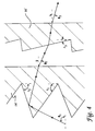
- Figure 3 graphically depicts one acceptable design of a doublet lens in accordance with the foregoing description, referenced by the groove angles F 1 , F 2 , and F 3 where F 1 is as above, F 2 is the reflecting (TIR) groove angle of catadioptric lens 28 , and F 3 is the refracting groove angle of dioptric lens 30 .
- F 1 is as above
- F 2 is the reflecting (TIR) groove angle of catadioptric lens 28
- F 3 is the refracting groove angle of dioptric lens 30 .
- Figure 2 is assumed to represent a marginal light ray near the corner of an A4 size stage, and the optical parameters of lens system 24 include an object distance of about 89 mm and an image distance of about 350 mm, the following values are representative:
- an alternative embodiment of lens system 24 comprises a catadioptric lens 28' which is convergent and has positive dispersion, and a dioptric lens 30' which is divergent and has negative dispersion.
- the following conditions must be satisfied: F 1 > ( ⁇ 1 - ⁇ 2 ) and ⁇ 2 > ⁇ 3 .
- Figure 5 graphically depicts one acceptable design of a doublet lens in accordance with this alternative embodiment.
- the catadioptric surface of lens 28 and the dioptric surface of lens 30 may further be combined into a single lens element 38 as depicted in Figure 6.
- Lens 38 is generally planar and has a catadioptric surface 40 which is convergent, and a dioptric surface 42 which is also convergent.
- the orientation of the grooves of dioptric surface 42 is selected to cancel out the dispersion at catadioptric surface 40 .
- FIG 7 graphically depicts one acceptable design of a singlet lens in accordance with this embodiment.
- Another singlet lens 38' shown in Figure 8 may be formed wherein dioptric surface 42 is divergent. In that singlet system, the following conditions must be satisfied: F 1 > ( ⁇ 1 - ⁇ 3 ) and ⁇ 2 > asin(sin( ⁇ 3 /n)).
- OHP 10 While the specific dimensions and optical parameters of OHP 10 may vary considerably depending upon the particular application, the following approximate values are considered exemplary.
- a varifocal lens having a focal length variation of 280 mm to 315 mm
- Dioptric Fresnel lens 30 having a focal length of 372 mm
- catadioptric lens 28 having a focal length of 89 mm
- Each lens is pressed in a 2 mm thick sheet of acrylic plastic (refractive index 1.492) and has a groove frequency between 2 and 16 grooves per millimeter.
- the ratio of the groove frequencies between the upper and lower elements are chosen to minimize Moiré pattern interference between the two groove structures.
- a typical groove frequency ratio is 4.74:1.
- the lenses are packaged together and sealed along their perimeters, with a 0 to 1 mm spacing between the upper (plano) surface of lens 28 and ridges 32 of lens 30 .
- Lamp 15 an incandescent 400 watt, 36 volt lamp of the EVD type
- a plano-convex condenser 34 with a focal length between 250 mm and 500 mm is located 11 mm above lamp 15
- the vertex of a back spherical reflector 36 with a dichroic cold mirror coating is located 25 mm below lamp 15 .
- the effective base height of this exemplary OHP is about 13 cm, resulting in a very portable machine, particularly when the projection head is folded downward.
Abstract
Claims (8)
- Rétroprojecteur comportant :une base (12) ayant une surface de support de document (14) ;une tête de projecteur (16) montée sur ladite base, à proximité de ladite surface de support de document ;une source lumineuse (15) située dans ladite base ;des moyens (34) pour diriger la lumière provenant de ladite source de lumière vers ladite surface de support de document ; etun système de lentilles de condensation (24) situé au niveau de ladite surface de support de document, ledit système de lentilles de condensation comportant :une lentille de Fresnel catadioptrique (28) ayant une surface supérieure plane et une surface inférieure, ladite surface inférieure ayant plusieurs arêtes et gorges prismatiques, ladite lentille catadioptrique ayant une dispersion entraînant en une aberration chromatique, etune lentille de Fresnel dioptrique (30) ayant une surface supérieure plane et une surface inférieure, ladite surface inférieure ayant plusieurs arêtes et gorges prismatiques (32) et étant située adjacente à ladite surface supérieure plane de ladite lentille catadioptrique, ladite lentille dioptrique ayant une dispersion généralement opposée à celle de ladite lentille catadioptrique de sorte que ladite aberration chromatique est pratiquement éliminée.
- Rétroprojecteur selon la revendication 1, dans lequel :ladite lentille catadioptrique est convergente et a une dispersion négative ;ladite lentille dioptrique est convergente et a une dispersion positive ; etles conditions suivantes sont satisfaites :où F1 est un angle de gorge de réfraction de ladite lentille catadioptrique, Φ1 est un angle d'entrée d'un rayon lumineux pénétrant dans ladite surface inférieure de ladite lentille catadioptrique, Φ2 est un angle intérieur d'un rayon lumineux situé entre ladite surface supérieure plane de ladite lentille catadioptrique et ladite surface inférieure de ladite lentille dioptrique, et Φ3 est un angle de sortie d'un rayon lumineux sortant de ladite surface supérieure plane de ladite lentille dioptrique.


- Rétroprojecteur selon la revendication 1, dans lequel :ladite lentille catadioptrique est convergente et a une dispersion positive ;ladite lentille dioptrique est divergente et a une dispersion négative ; etles conditions suivantes sont satisfaites :où F1 est un angle de gorge de réfraction de ladite lentille catadioptrique, Φ1 est un angle d'entrée d'un rayon lumineux pénétrant dans ladite surface inférieure de ladite lentille catadioptrique, Φ2 est un angle intérieur d'un rayon lumineux situé entre ladite surface supérieure plane de ladite lentille catadioptrique et ladite surface inférieure de ladite lentille dioptrique, et Φ3 est un angle de sortie d'un rayon lumineux sortant de ladite surface supérieure plane de ladite lentille dioptrique.


- Rétroprojecteur selon la revendication 1, dans lequel :lesdites arêtes et gorges de ladite lentille catadioptrique Sont généralement circulaires, définissant un centre effectif ;lesdites arêtes et gorges de ladite lentille dioptrique sont généralement circulaires, définissant un centre effectif ; etlesdites lentilles dioptrique et catadioptrique sont orientées de sorte que ledit centre effectif de ladite lentille dioptrique soit situé au-dessus dudit centre effectif de ladite lentille catadioptrique.
- Rétroprojecteur comportant :une base (12) ayant une surface de support de document (14) ;une tête de projecteur (16) montée sur ladite base, à proximité de ladite surface de support de document ;une source lumineuse (15) située dans ladite base ;des moyens (34) pour diriger la lumière depuis ladite source lumineuse vers ladite surface de support de document ; etune lentille unique achromatique (38) située à ladite surface de support de document, ladite lentille unique comportant :un substrat généralement plan ayant une première et seconde surfaces,ladite première surface (40) ayant plusieurs arêtes et gorges prismatiques formant une surface catadioptrique, lesdites arêtes et gorges de ladite surface catadioptrique étant généralement circulaires, définissant un centre effectif, et ladite surface catadioptrique présentant une dispersion,ladite seconde surface (42) ayant plusieurs arêtes et gorges prismatiques formant une surface dioptrique, lesdites arêtes et gorges de ladite lentille dioptrique étant généralement circulaires, définissant un centre effectif, et lesdites arêtes et gorges de ladite surface dioptrique étant orientées pour pratiquement annuler ladite dispersion de ladite surface catadioptrique, etledit centre effectif de ladite lentille dioptrique coïncidant avec ledit centre effectif de ladite lentille catadioptrique.
- Rétroprojecteur selon la revendication 5, dans lequel :ladite surface catadioptrique est convergente ;ladite surface dioptrique est convergente ; etles conditions suivantes sont satisfaites :où F1 est un angle de gorge de réfraction de ladite surface catadioptrique, Φ1 est un angle d'entrée d'un rayon lumineux pénétrant dans ladite surface catadioptrique, Φ2 est un angle intérieur dudit rayon lumineux situé entre ladite surface catadioptrique et ladite surface dioptrique, Φ3 est un angle de sortie dudit rayon lumineux sortant de ladite surface dioptrique, et n est l'indice de réfraction du substrat.


- Rétroprojecteur selon la revendication 5, dans lequel :ladite surface catadioptrique est convergente ;ladite surface dioptrique est divergente etles conditions suivantes sont satisfaites :où F1 est un angle de gorge de réfraction de ladite surface catadioptrique, Φ1 est un angle d'entrée d'un rayon lumineux pénétrant dans ladite surface catadioptrique, Φ2 est un angle intérieur dudit rayon lumineux situé entre ladite surface catadioptrique et ladite surface dioptrique, Φ3 est un angle de sortie dudit rayon lumineux sortant de ladite surface dioptrique, et n est l'indice de réfraction du substrat.


- Rétroprojecteur comportant :une base (12) ayant une surface de support de document (14) ;une tête de projecteur (16) montée sur ladite base, à proximité de ladite surface de support de document ;une source lumineuse (15) située dans ladite base ;une lentille formant condenseur (34) située adjacente à ladite source lumineuse, entre ladite source lumineuse et ladite surface de support de document ;un réflecteur arrière (36) situé adjacent à ladite source lumineuse, à l'opposé de ladite lentille de condensation ; etun système de lentilles de condensation (24) situé à ladite surface de support de document, ledit système de lentilles de condensation comportant :une lentille de Fresnel catadioptrique (30), convergente, ayant une surface supérieure plane et une surface inférieure, ladite surface inférieure ayant plusieurs arêtes et gorges prismatiques, généralement circulaires, définissant un centre effectif, ladite lentille catadioptrique ayant une dispersion négative, etune lentille de Fresnel dioptrique (28), convergente, généralement parallèle à ladite lentille catadioptrique, ayant une surface supérieure plane et une surface inférieure, ladite surface inférieure ayant plusieurs arêtes et gorges prismatiques définissant un centre effectif et étant située adjacente à ladite surface supérieure plane de ladite lentille catadioptrique de sorte que ledit centre effectif de ladite lentille dioptrique est situé au-dessus dudit centre effectif de ladite lentille catadioptrique, ladite lentille dioptrique ayant une dispersion positive,lesdites lentilles dioptrique et catadioptrique étant constituées d'une matière thermoplastique polymérique ayant un indice de réfraction d'au moins environ 1,4, et se conformant aux conditions :où F1 est un angle de gorge de réfraction de ladite lentille catadioptrique, Φ1 est un angle d'entrée d'un rayon lumineux pénétrant dans ladite surface inférieure de ladite lentille catadioptrique, Φ2 est un angle intérieur d'un rayon lumineux situé entre ladite surface supérieure plane de ladite lentille catadioptrique et ladite surface inférieure de ladite lentille dioptrique, et Φ3 est un angle de sortie d'un rayon lumineux sortant de ladite surface supérieure plane de ladite lentille dioptrique.


Applications Claiming Priority (3)
| Application Number | Priority Date | Filing Date | Title |
|---|---|---|---|
| US08/084,513 US5317349A (en) | 1993-06-29 | 1993-06-29 | Overhead projector with achromatic fresnel lens |
| US84513 | 1993-06-29 | ||
| PCT/US1994/005934 WO1995001587A1 (fr) | 1993-06-29 | 1994-05-26 | Retroprojecteur a lentilles de fresnel achromatiques |
Publications (2)
| Publication Number | Publication Date |
|---|---|
| EP0706676A1 EP0706676A1 (fr) | 1996-04-17 |
| EP0706676B1 true EP0706676B1 (fr) | 1997-03-12 |
Family
ID=22185424
Family Applications (1)
| Application Number | Title | Priority Date | Filing Date |
|---|---|---|---|
| EP94918133A Expired - Lifetime EP0706676B1 (fr) | 1993-06-29 | 1994-05-26 | Retroprojecteur a lentilles de fresnel achromatiques |
Country Status (10)
| Country | Link |
|---|---|
| US (2) | US5317349A (fr) |
| EP (1) | EP0706676B1 (fr) |
| JP (1) | JPH08512142A (fr) |
| KR (1) | KR960702911A (fr) |
| CN (1) | CN1056930C (fr) |
| DE (1) | DE69402073T2 (fr) |
| HK (1) | HK1006879A1 (fr) |
| SI (1) | SI9420038A (fr) |
| TW (1) | TW217446B (fr) |
| WO (1) | WO1995001587A1 (fr) |
Families Citing this family (20)
| Publication number | Priority date | Publication date | Assignee | Title |
|---|---|---|---|---|
| US5296882A (en) * | 1992-12-21 | 1994-03-22 | Minnesota Mining And Manufacturing Company | Overhead projector with catadioptric fresnel lens |
| US5317349A (en) * | 1993-06-29 | 1994-05-31 | Minnesota Mining And Manufacturing Company | Overhead projector with achromatic fresnel lens |
| DE69509074T2 (de) * | 1994-02-16 | 1999-12-09 | Minnesota Mining & Mfg | Fresnellinse mit stufen auf beiden seiten fuer overheadprojektion |
| US5515123A (en) * | 1994-02-17 | 1996-05-07 | Minnesota Mining And Manufacturing Company | Condensers for illumination systems |
| JP3409587B2 (ja) * | 1996-05-14 | 2003-05-26 | オムロン株式会社 | 光路変換光学素子、画像表示装置及び光投射器 |
| US5997709A (en) * | 1996-05-28 | 1999-12-07 | Minnesota Mining And Manufacturing Co. | Method of providing diffuse risers on a fresnel lens die |
| DE69837591T2 (de) * | 1997-12-16 | 2007-12-27 | KURARAY CO., LTD, Kurashiki | Rückprojektionsschirm mit einem Prisma |
| JP2001337206A (ja) * | 2000-05-26 | 2001-12-07 | Toppan Printing Co Ltd | フレネルレンズ |
| US6914723B2 (en) * | 2001-11-09 | 2005-07-05 | Xradia, Inc. | Reflective lithography mask inspection tool based on achromatic Fresnel optics |
| US6917472B1 (en) * | 2001-11-09 | 2005-07-12 | Xradia, Inc. | Achromatic fresnel optics for ultraviolet and x-ray radiation |
| JP2008512700A (ja) * | 2004-09-07 | 2008-04-24 | コーニンクレッカ フィリップス エレクトロニクス エヌ ヴィ | フレネル構造を有する光学素子 |
| US20070091452A1 (en) * | 2005-10-25 | 2007-04-26 | Scott Lerner | Projection system and method |
| JP4743607B2 (ja) * | 2005-12-22 | 2011-08-10 | 株式会社ニコン | フレネルレンズ、および、このフレネルレンズを用いた液晶プロジェクタ |
| JP5827104B2 (ja) * | 2010-11-19 | 2015-12-02 | 株式会社半導体エネルギー研究所 | 照明装置 |
| CN102183823A (zh) * | 2011-05-10 | 2011-09-14 | 南京邮电大学 | 一种光纤准直器 |
| JP5192067B2 (ja) * | 2011-09-09 | 2013-05-08 | シャープ株式会社 | フレネルレンズ |
| USD744155S1 (en) * | 2014-05-28 | 2015-11-24 | Osram Sylvania Inc. | Lens |
| US11588137B2 (en) | 2019-06-05 | 2023-02-21 | Semiconductor Energy Laboratory Co., Ltd. | Functional panel, display device, input/output device, and data processing device |
| US11659758B2 (en) | 2019-07-05 | 2023-05-23 | Semiconductor Energy Laboratory Co., Ltd. | Display unit, display module, and electronic device |
| JPWO2021009587A1 (fr) | 2019-07-12 | 2021-01-21 |
Family Cites Families (26)
| Publication number | Priority date | Publication date | Assignee | Title |
|---|---|---|---|---|
| US2003804A (en) * | 1932-07-21 | 1935-06-04 | Gen Motors Corp | Lens |
| JPS51933Y1 (fr) * | 1969-06-17 | 1976-01-12 | ||
| US3712713A (en) * | 1970-08-10 | 1973-01-23 | Minnesota Mining & Mfg | Optical shield of transparant intermeshed grooved panels useful on overhead projects |
| US4118114A (en) * | 1974-08-21 | 1978-10-03 | Minnesota Mining And Manufacturing Company | Low-glare overhead projector |
| US3982822A (en) * | 1975-03-03 | 1976-09-28 | Minnesota Mining And Manufacturing Company | Composite Fresnel lens assembly |
| US4108540A (en) * | 1976-06-17 | 1978-08-22 | Minnesota Mining And Manufacturing Company | Refractor-reflector radiation concentrator |
| US4118761A (en) * | 1977-02-28 | 1978-10-03 | Bausch & Lomb Incorporated | Light condensing illuminator |
| JPS5560934A (en) * | 1978-10-31 | 1980-05-08 | Gakken Co Ltd | Color band removing focus adjusting method in overhead projector |
| US4337759A (en) * | 1979-10-10 | 1982-07-06 | John M. Popovich | Radiant energy concentration by optical total internal reflection |
| US4436392A (en) * | 1983-01-03 | 1984-03-13 | Minnesota Mining And Manufacturing Company | Distortion correction for an overhead projector system |
| US4436393A (en) * | 1983-01-03 | 1984-03-13 | Minnesota Mining And Manufacturing Company | Distortion correction for an overhead projector system |
| DE3519506A1 (de) * | 1985-05-31 | 1986-12-04 | Demolux Gmbh & Co Kg, 6070 Langen | Overhead-projektor |
| US4755921A (en) * | 1986-04-02 | 1988-07-05 | Minnesota Mining And Manufacturing Company | Lens |
| US4741613A (en) * | 1986-12-19 | 1988-05-03 | Minnesota Mining And Manufacturing Company | Reduced height transmissive overhead projector |
| US4859043A (en) * | 1987-05-07 | 1989-08-22 | Cibie Projecteurs | High efficiency signal light, in particular for a motor vehicle |
| DE3728191C1 (de) * | 1987-08-24 | 1989-02-23 | Medium Vertriebsgesellschaft F | Durchlicht-Schreibprojektor |
| US5161057A (en) * | 1988-09-12 | 1992-11-03 | Johnson Kenneth C | Dispersion-compensated fresnel lens |
| US5208620A (en) * | 1988-10-04 | 1993-05-04 | Canon Kabushiki Kaisha | Display apparatus |
| US4900129A (en) * | 1988-12-16 | 1990-02-13 | Minnesota Mining And Manufacturing Company | Dual grooved Fresnel lens for overhead projection |
| US5097395A (en) * | 1989-02-24 | 1992-03-17 | Minnesota Mining And Manufacturing Company | Multiple cavity light fixture |
| US4969733A (en) * | 1989-10-02 | 1990-11-13 | Dukane Corporation | Foldable portable overhead projector |
| EP0422661A3 (en) * | 1989-10-13 | 1992-07-01 | Mitsubishi Rayon Co., Ltd | Polarization forming optical device and polarization beam splitter |
| US5150966A (en) * | 1990-09-19 | 1992-09-29 | Minnesota Mining And Manufacturing Company | Uniform intensity profile catadioptric lens |
| GB9108033D0 (en) * | 1991-04-16 | 1991-06-05 | Britax Vega Ltd | Vehicle lamp |
| US5296882A (en) * | 1992-12-21 | 1994-03-22 | Minnesota Mining And Manufacturing Company | Overhead projector with catadioptric fresnel lens |
| US5317349A (en) * | 1993-06-29 | 1994-05-31 | Minnesota Mining And Manufacturing Company | Overhead projector with achromatic fresnel lens |
-
1993
- 1993-06-29 US US08/084,513 patent/US5317349A/en not_active Expired - Fee Related
- 1993-07-09 TW TW082105488A patent/TW217446B/zh active
-
1994
- 1994-03-29 US US08/219,654 patent/US5453880A/en not_active Expired - Fee Related
- 1994-05-26 WO PCT/US1994/005934 patent/WO1995001587A1/fr active IP Right Grant
- 1994-05-26 EP EP94918133A patent/EP0706676B1/fr not_active Expired - Lifetime
- 1994-05-26 SI SI9420038A patent/SI9420038A/sl unknown
- 1994-05-26 JP JP7503478A patent/JPH08512142A/ja active Pending
- 1994-05-26 CN CN94192596A patent/CN1056930C/zh not_active Expired - Fee Related
- 1994-05-26 DE DE69402073T patent/DE69402073T2/de not_active Expired - Fee Related
-
1995
- 1995-12-01 KR KR1019950705420A patent/KR960702911A/ko not_active Application Discontinuation
-
1998
- 1998-06-22 HK HK98105953A patent/HK1006879A1/xx not_active IP Right Cessation
Also Published As
| Publication number | Publication date |
|---|---|
| CN1126521A (zh) | 1996-07-10 |
| TW217446B (en) | 1993-12-11 |
| DE69402073T2 (de) | 1997-10-09 |
| DE69402073D1 (de) | 1997-04-17 |
| US5453880A (en) | 1995-09-26 |
| WO1995001587A1 (fr) | 1995-01-12 |
| US5317349A (en) | 1994-05-31 |
| CN1056930C (zh) | 2000-09-27 |
| KR960702911A (ko) | 1996-05-23 |
| SI9420038A (en) | 1996-06-30 |
| EP0706676A1 (fr) | 1996-04-17 |
| JPH08512142A (ja) | 1996-12-17 |
| HK1006879A1 (en) | 1999-03-19 |
Similar Documents
| Publication | Publication Date | Title |
|---|---|---|
| US5296882A (en) | Overhead projector with catadioptric fresnel lens | |
| EP0706676B1 (fr) | Retroprojecteur a lentilles de fresnel achromatiques | |
| US6896375B2 (en) | Rear projection display device having multiple mirrors that are substantially parallel to a screen | |
| US6999232B2 (en) | Rear projection display system | |
| US6332688B1 (en) | Apparatus for uniformly illuminating a light valve | |
| JP5639174B2 (ja) | 統合された視覚及び表示システム | |
| US8139909B2 (en) | Illuminator method and device | |
| US4741613A (en) | Reduced height transmissive overhead projector | |
| EP0793816B1 (fr) | Projecteur a source de lumiere equipee de plusieurs lampes | |
| EP2410378A1 (fr) | Système optique de projection et dispositif de projection d'image | |
| TWI345675B (en) | Projection lens and projector | |
| US3927941A (en) | Photographic enlarger mixing box | |
| US5572362A (en) | Condenser lens, polarizing element, light source apparatus, and projection display apparatus | |
| WO1995022772A1 (fr) | Lentille de fresnel double echelon pour retroprojecteur | |
| KR20130035333A (ko) | 반사 장치 및 이를 구비한 빔 프로젝터 | |
| WO2005040912A1 (fr) | Affichage a projection arriere | |
| CA2203266A1 (fr) | Projecteur a source de lumiere equipee de plusieurs lampes |
Legal Events
| Date | Code | Title | Description |
|---|---|---|---|
| PUAI | Public reference made under article 153(3) epc to a published international application that has entered the european phase |
Free format text: ORIGINAL CODE: 0009012 |
|
| 17P | Request for examination filed |
Effective date: 19951205 |
|
| AK | Designated contracting states |
Kind code of ref document: A1 Designated state(s): DE FR GB IT NL |
|
| GRAG | Despatch of communication of intention to grant |
Free format text: ORIGINAL CODE: EPIDOS AGRA |
|
| GRAH | Despatch of communication of intention to grant a patent |
Free format text: ORIGINAL CODE: EPIDOS IGRA |
|
| 17Q | First examination report despatched |
Effective date: 19960730 |
|
| GRAH | Despatch of communication of intention to grant a patent |
Free format text: ORIGINAL CODE: EPIDOS IGRA |
|
| GRAH | Despatch of communication of intention to grant a patent |
Free format text: ORIGINAL CODE: EPIDOS IGRA |
|
| GRAA | (expected) grant |
Free format text: ORIGINAL CODE: 0009210 |
|
| AK | Designated contracting states |
Kind code of ref document: B1 Designated state(s): DE FR GB IT NL |
|
| REF | Corresponds to: |
Ref document number: 69402073 Country of ref document: DE Date of ref document: 19970417 |
|
| ET | Fr: translation filed | ||
| ITF | It: translation for a ep patent filed |
Owner name: PORTA CHECCACCI E BOTTI S.R.L. |
|
| PLBE | No opposition filed within time limit |
Free format text: ORIGINAL CODE: 0009261 |
|
| STAA | Information on the status of an ep patent application or granted ep patent |
Free format text: STATUS: NO OPPOSITION FILED WITHIN TIME LIMIT |
|
| 26N | No opposition filed | ||
| REG | Reference to a national code |
Ref country code: GB Ref legal event code: IF02 |
|
| PGFP | Annual fee paid to national office [announced via postgrant information from national office to epo] |
Ref country code: FR Payment date: 20020501 Year of fee payment: 9 |
|
| PGFP | Annual fee paid to national office [announced via postgrant information from national office to epo] |
Ref country code: NL Payment date: 20020507 Year of fee payment: 9 |
|
| PGFP | Annual fee paid to national office [announced via postgrant information from national office to epo] |
Ref country code: DE Payment date: 20020520 Year of fee payment: 9 |
|
| PGFP | Annual fee paid to national office [announced via postgrant information from national office to epo] |
Ref country code: GB Payment date: 20020522 Year of fee payment: 9 |
|
| PG25 | Lapsed in a contracting state [announced via postgrant information from national office to epo] |
Ref country code: GB Free format text: LAPSE BECAUSE OF NON-PAYMENT OF DUE FEES Effective date: 20030526 |
|
| PG25 | Lapsed in a contracting state [announced via postgrant information from national office to epo] |
Ref country code: NL Free format text: LAPSE BECAUSE OF NON-PAYMENT OF DUE FEES Effective date: 20031201 |
|
| PG25 | Lapsed in a contracting state [announced via postgrant information from national office to epo] |
Ref country code: DE Free format text: LAPSE BECAUSE OF NON-PAYMENT OF DUE FEES Effective date: 20031202 |
|
| GBPC | Gb: european patent ceased through non-payment of renewal fee |
Effective date: 20030526 |
|
| PG25 | Lapsed in a contracting state [announced via postgrant information from national office to epo] |
Ref country code: FR Free format text: LAPSE BECAUSE OF NON-PAYMENT OF DUE FEES Effective date: 20040130 |
|
| NLV4 | Nl: lapsed or anulled due to non-payment of the annual fee |
Effective date: 20031201 |
|
| REG | Reference to a national code |
Ref country code: FR Ref legal event code: ST |
|
| PG25 | Lapsed in a contracting state [announced via postgrant information from national office to epo] |
Ref country code: IT Free format text: LAPSE BECAUSE OF NON-PAYMENT OF DUE FEES Effective date: 20050526 |