EP0706146A2 - Analyseverfahren für kreisformige Streifencodes - Google Patents
Analyseverfahren für kreisformige Streifencodes Download PDFInfo
- Publication number
- EP0706146A2 EP0706146A2 EP95305617A EP95305617A EP0706146A2 EP 0706146 A2 EP0706146 A2 EP 0706146A2 EP 95305617 A EP95305617 A EP 95305617A EP 95305617 A EP95305617 A EP 95305617A EP 0706146 A2 EP0706146 A2 EP 0706146A2
- Authority
- EP
- European Patent Office
- Prior art keywords
- elements
- bar code
- signal
- circular bar
- adjacent
- Prior art date
- Legal status (The legal status is an assumption and is not a legal conclusion. Google has not performed a legal analysis and makes no representation as to the accuracy of the status listed.)
- Withdrawn
Links
Images


Classifications
-
- G—PHYSICS
- G06—COMPUTING OR CALCULATING; COUNTING
- G06K—GRAPHICAL DATA READING; PRESENTATION OF DATA; RECORD CARRIERS; HANDLING RECORD CARRIERS
- G06K7/00—Methods or arrangements for sensing record carriers, e.g. for reading patterns
- G06K7/10—Methods or arrangements for sensing record carriers, e.g. for reading patterns by electromagnetic radiation, e.g. optical sensing; by corpuscular radiation
- G06K7/14—Methods or arrangements for sensing record carriers, e.g. for reading patterns by electromagnetic radiation, e.g. optical sensing; by corpuscular radiation using light without selection of wavelength, e.g. sensing reflected white light
- G06K7/1404—Methods for optical code recognition
- G06K7/1408—Methods for optical code recognition the method being specifically adapted for the type of code
- G06K7/1421—Circular bar codes
-
- G—PHYSICS
- G06—COMPUTING OR CALCULATING; COUNTING
- G06K—GRAPHICAL DATA READING; PRESENTATION OF DATA; RECORD CARRIERS; HANDLING RECORD CARRIERS
- G06K19/00—Record carriers for use with machines and with at least a part designed to carry digital markings
- G06K19/06—Record carriers for use with machines and with at least a part designed to carry digital markings characterised by the kind of the digital marking, e.g. shape, nature, code
- G06K19/06009—Record carriers for use with machines and with at least a part designed to carry digital markings characterised by the kind of the digital marking, e.g. shape, nature, code with optically detectable marking
- G06K19/06046—Constructional details
- G06K19/06168—Constructional details the marking being a concentric barcode
-
- G—PHYSICS
- G06—COMPUTING OR CALCULATING; COUNTING
- G06K—GRAPHICAL DATA READING; PRESENTATION OF DATA; RECORD CARRIERS; HANDLING RECORD CARRIERS
- G06K7/00—Methods or arrangements for sensing record carriers, e.g. for reading patterns
- G06K7/10—Methods or arrangements for sensing record carriers, e.g. for reading patterns by electromagnetic radiation, e.g. optical sensing; by corpuscular radiation
- G06K7/14—Methods or arrangements for sensing record carriers, e.g. for reading patterns by electromagnetic radiation, e.g. optical sensing; by corpuscular radiation using light without selection of wavelength, e.g. sensing reflected white light
-
- G—PHYSICS
- G06—COMPUTING OR CALCULATING; COUNTING
- G06K—GRAPHICAL DATA READING; PRESENTATION OF DATA; RECORD CARRIERS; HANDLING RECORD CARRIERS
- G06K19/00—Record carriers for use with machines and with at least a part designed to carry digital markings
- G06K19/06—Record carriers for use with machines and with at least a part designed to carry digital markings characterised by the kind of the digital marking, e.g. shape, nature, code
- G06K2019/06215—Aspects not covered by other subgroups
- G06K2019/06243—Aspects not covered by other subgroups concentric-code
Definitions
- This application relates to a method for evaluating data received from scanning a circular bar code label.
- Bar code labels are utilized in a variety of applications to provide numerical identification, typically about an item carrying the label.
- a bar code consists of a series of alternate spaces, or light elements, and bars, or dark elements, with the light and dark elements being comprised of a series of wide and narrow elements. In the past, these elements have been positioned extending along a linear direction.
- a start code pattern is embedded at one end of the bar code label comprised of a known series of elements, and a stop code pattern is formed at the other end. Further, a wide "quiet zone" is formed at each end of the bar code label. The quiet zones and the start/stop patterns allow the scanner system to determine the starting and ending points of the label, and determine when to begin to evaluate the information read from the label and when to stop.
- the analog readings from a bar code scanner are not constant, even during a single scanning of a single bar code label.
- Many variables affect the analog signal from the bar code scanner.
- the analog signal for several dark elements may have widely varying peak values.
- the signal level can vary from element to element as the contrast on the label changes, or as the angle of the back scattering from the label varies.
- the above variation presents a problem when converting the analog information into digital information.
- This conversion requires a precise determination of the width of the code elements which are made up of bars and spaces. To make this determination, the system must identify the transitions between the dark and light elements, and switch the digital signal when a transition occurs.
- a reference voltage is set to identify a transition. Because of the above described variation, however, a fixed threshold or an averaging variable threshold circuit has not been found to be reliable to identify the transitions. Neither type circuit can track nor predict the amplitude of the next transition to be switched between the dark and light elements, or vice versa.
- linear bar code labels provide a very efficient method of reporting data relative to a member which carries the label, they have certain limitations in that they require a relatively large amount of space. Certain applications do not have sufficient space, and thus have not been able to successfully use bar code technology. As an example, small circular elements such as medical test tubes, and sample vials have not been readily adapted to the use of linear bar code labels.
- a linear bar code label is placed on a curved structure, such as a test tube, other problems are presented in that the starting point for the label, and its relative position to a reader, must be carefully controlled to provide accurate results from the scanning of that label. The label must be positioned such that the beam passes through each element on the label, and this has been difficult to achieve with a linear label on a curved surface.
- the present invention includes a method of evaluating data from a circular bar code label.
- the use of a circular bar code label provides maximum utilization of the space taken by the label, and is particularly valuable when used on small circular or curved elements such as test tubes.
- the circular bar code of the invention carries about three times the information that a linear, conventional bar code label could carry per unit of length.
- the circular bar code label is continuous, one need not worry about properly aligning the scanner with a starting point for the label before beginning scanning. Rather, since the code is circular and continuous, the system for evaluating the data from the scanner will eventually cross and recognize the starting point of the code on the label.
- several methods for evaluating data from scanning a circular bar code label includes the step of comparing a particular element to adjacent elements to determine whether the particular element is a wide or narrow element.
- the label is scanned continuously, and an analog signal develops. That analog signal is converted into a digital signal comprising a series of low and high logic levels corresponding to dark or light elements.
- the disclosed circular bar code includes a series of wedge-shaped narrow and wide elements. With such wedge-shaped elements, should the scanner be offset from the center of the circular bar code label, it is possible that a misreading could occur.
- the width of the elements change as the radial distance from the center of the circular bar code label changes. Radially inner portions of the elements are relatively small when compared to the radially outer portions. It is possible that a wide element, read at its radially inner position, could be mistaken for a narrow element. Similarly, it is possible that a narrow element could be read near a radially outer position, and that narrow element be mistaken for a wide element. Mistaken identification could result in a misidentification of the information on the bar code label.
- Applicant has determined that the width of adjacent elements of identical logical dimension do not vary significantly, even when the bar code reader is grossly offset relative to the center of the circular bar code label.
- inventive methods compare an element under consideration to adjacent elements, and reach a determination of whether the element is narrow or wide based upon that comparison.
- each of the code elements for a given number is compared to an adjacent element, and a ratio is determined of those elements.
- a ratio is determined of those elements.
- the widths of five code elements for a given numeral are A, B, C, D, and E
- ratios A/B, B/C, C/D, and D/E are determined.
- Each numeral identified by those five symbols has a unique set of four ratios.
- sets of elements make up a code for each of the numerals 0-9.
- the method includes the step of averaging the measured width of all dark or light elements for each numeral. Since this is a local average, the elements would all be adjacent to each other in the code, and thus variation due to offset will not be significant.
- the measured widths of each of the elements are then compared to their respective averages. If an element under consideration is greater than the average, then a determination is made that the element is a wide element. If the width is less than the average, a determination is made that the element is narrow. This sequence of calculation is done for each numeral of the code. Once the system has determined the arrangement of wide and narrow elements, it is relatively simple to compare that arrangement to a standard key and determine the information on the bar code label.
- a memory stores a previously read element, and also stores whether that previous element is a wide or narrow element.
- An initial storage "previous" element may be found from a standard signal found at the start code pattern of the label. As an example, the system may know that the pattern includes two successive narrow elements. The system may then store those initial elements into its memory as the "previous element" when beginning to make determinations on subsequent elements. Each subsequent element is compared to an element in storage. Should the width of the element under consideration differ greatly from the previous elements, a determination is made that the element under consideration is different than the previously stored element. On the other hand, if the width is found to be approximately equal to that of the element in storage, a determination can be made that the two are the same.
- the element in storage is known to be narrow, and the element under consideration is of a width that approximates that of the previous element, a determination can be made that the element under consideration is also narrow.
- the element under consideration is of a width that is quite different than the element in storage, then a determination can be made that the two elements are different. If the element in storage is narrow, and the element under consideration is found to be of a much greater width than the element in storage, a determination can be made that the element under consideration is a wide element. Similarly, if an element is found to be of a width much less than a previous element that is known to be a wide element, it will be safe to assume that the element under consideration is a narrow element.
- the initial "previous" element may be re-established for each new group of code elements that are examined and which form a single character. This may be done by finding the narrowest code element within that group which becomes the "previous” element of that group. Each numeral includes at least one narrow element, and thus it is safe to assume that the "narrowest” element is a narrow code element. All the code elements of that group, which together constitute a single numeral or character can then be identified and the numeral can be decoded. This process continues by re-establishing the initial "previous” element and then analyzing the code elements of the next character of the bar code label, until all the numerals of the label have been identified.
- Another variation of the above method is to evaluate and find the narrowest code element and the widest code element within the code pattern of a single character and store them both as the previous elements. All the other code elements, within that particular character, are then evaluated with respect to the narrow element and then with respect to the wide element. All of these methods should provide identical results.
- a difference factor of about three is typically formed between the narrow and wide elements.
- a factor of 1.5 or as much as 2.0 may be utilized to determine whether the width of an element under consideration is sufficiently different than the stored element, such that a determination can be made that the elements are different.
- the exact factors used can vary and form no portion of this invention.
- the analog signal from the scanner is converted to a digital signal by a unique method of determining when a transition between light and dark elements occurs.
- a transition between light and dark elements there is no standard signal strength for either the dark or light elements. This presents a problem in determining when to switch the digital signal between the dark and light elements.
- Applicant addresses this problem by splitting the time derivative of the analog signal into two channels, or branches, and delaying one of those branches. The second branch is sent to a circuit which determines the proper switching threshold of the delayed analog signal. A threshold signal which is proportional to the peak value is generated and compared to the delayed signal. When the delayed signal crosses the proportional signal by an infinitesimal quantity, a switching occurs from analog to digital.
- the invention is based on the operation of a proportional threshold circuit which produces a threshold level for switching the approaching delayed signal at a value that is preferably very close to the midpoint of the delayed signal.
- This aspect of the invention has applications not only in circular bar code labels, but also in linear bar code labels.
- Figure 1 is a view of a prior art linear bar code label.
- Figure 2 is a view of a circular bar code label according to the present invention.
- Figure 3 is a view of a system for reading a circular bar code label.
- Figure 4 shows a circular bar code reader with an offset scanning beam.
- Figure 5 is a schematic of an analog to digital conversion circuit.
- Figure 6A shows the analog signal at an initial location in the circuit of Figure 5.
- Figure 6B shows the analog signal at a subsequent point in the circuit of Figure 5.
- Figure 6C shows the analog signal at yet another subsequent point in the circuit of Figure 5.
- Figure 6D shows the analog signal at yet another subsequent time in the circuit of Figure 5.
- Figure 6E shows a portion of the analog signal at another subsequent point in the circuit of Figure 5.
- Figure 6F shows a second portion of the analog signal at another subsequent point in the circuit of Figure 5.
- Figure 6G shows the digital signal provided by the circuit of Figure 5.
- Figure 7 shows a flow chart for a first embodiment method according to the present invention.
- Figure 8 shows a flow chart for a second embodiment method according to the present invention.
- Figure 9 shows a flow chart for third embodiment method according to the present invention.
- Figure 1 shows a liner bar code label 20 which includes a start code pattern 22, positioned adjacent to a quiet zone 24. At the opposite end of label 20 is a stop pattern 26, and a quiet zone 28.
- a system for scanning the bar code label 20 "knows" that after the quiet zone 24, the start of code 22 occurs.
- the system recognizes that the start of code comprises a known pattern such as the illustrated two spaced narrow dark elements and two narrow light elements.
- the system recognizes that the subsequent series of dark or light, wide and narrow elements provide a code that represents particular numerals.
- the dark elements represent a first numeral
- the light elements represent a second numeral.
- the system analyzes the arrangement of the narrow and wide elements to determine the numerals embodied in the bar code label.
- linear bar code labels have achieved wide acceptance, in some applications they have not been practically utilized since they require more space than may be available.
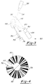
- FIG. 2 shows a circular bar code label 30.
- a quiet zone 34 is located between start code 32 and stop code pattern 36. Should reading of the circular bar code label 30 begin at a position other than the start code 32, the system will disregard these code elements and will start to acquire data after the quiet zone 34 is passed.
- the quiet zone 34 is typically on the order of 10 times the width of a narrow element. This relatively large size insures that no matter how far offset the reader may be, the system will recognize the quiet zone 34.
- the bar code label 30 there are wide dark elements, such as 38, and narrow dark elements, such as 42. Similarly, there are narrow light elements 40 and wide light elements 44.
- the bar code label carries encoded information.
- a numerical code on the bar code label 30 could identify information about a particular patient associated with a test tube that may carry the bar code label 30.
- a first numeral is encoded by a particular order of five dark elements and a second numeral of five light elements. It is the arrangement of the narrow and wide elements that represent encoded data in a bar code label and which is decoded by a bar code reader.
- Other types of bar code symbologies are known, and this invention is not limited to any particular type of bar code symbology.
- a system 50 for reading a bar code label is illustrated in Figure 3.
- a laser source 52 directs a collimated beam 54 at a mirror 56.
- Mirror 56 deflects the beam, as shown at 58, towards a circular concave mirror 60.
- Mirror 60 is connected to an eccentric adaptor 62 which is driven by a rotary motor 64.
- Rotary motor 64 is controlled to rotate adaptor 62, and hence mirror 60. This rotation causes scanning beam 66 to generate a circular scanning beam on circular bar code label 68.
- a back scattered modulated optical signal 70 is directed off the bar code label 68 and focused by a lens 72 onto a photodetector 74.
- Photodetector 74 outputs an analog current signal that is proportional to the optical modulated signal to a system as will be described below.
- a charged-coupled device may be utilized to take a "snapshot" of the bar code label 68 for evaluation.
- the CCD camera may be of the matrix camera type or may be of the one-dimensional circular array type. The technology to perform such a method is well known to those skilled in the respective arts.
- a system 84 for converting the analog signal from the photodetector to a digital signal is disclosed in Figure 5.
- the conversion will be explained with reference to Figure 5 and Figures 6A-6G.
- the signals shown in Figure 6A-6G are representations of one potential set of values. The signals will vary with the signal read from the bar code label, and with the elements as encoded on the bar code label.
- An analog signal from photodetector 85 is sent to a two-stage preamplifier 86. The signal at that point may resemble the signal as shown in Figure 6A.
- the signal leaving element 90 may resemble the wave form as shown in Figure 6C. Element 90 blocks low level noise, and provides signal gain.
- the analog signal is split into two channels or branches.
- a first branch passes to a delay element 92.
- the second branch is directed to a variable threshold generator 94, producing a signal that is proportional to the delayed signal to be switched.
- Element 94 senses the full amplitude of the analog signal. Once a peak value is detected, a signal proportional to that peak value is generated.
- the element 94 represents a pair of dual switchable integrators, with one for negative transitions as found at the start of scanning a bar, and one for positive transitions as found at the start of scanning a space.
- the proportional signal produces a switching threshold that is preferably a fraction of the delayed signal, and most preferably one half the peak value. The proportional signal would then also approximate the midpoint of the incoming delayed signal.
- the proportional signal is sent through negative line 96 to a differential comparator 100. This is the signal shown at Figure 6F. If, on the other hand, the signal is a positive signal, as would be the case when a transition to a light element is being read, the signal would be sent through positive line 98 to the differential comparator 100. This is the signal shown in Figure 6E.
- the analog signal from the delay 92 is then compared to the threshold signal from lines 96 or 98. When the delayed signal 92 crosses the threshold signal by an infinitesimal value, a determination is made that the analog signal from delay 92 has changed between a light or dark element.
- the related negative dark threshold signal is sent through line 96 to the differential comparator.
- the digital signal at 6G changes to a logic low, indicating a bar.
- the threshold value found at line 98 the digital signal at 6G changes to a logic high, indicating a space.
- the output of comparator 100 is a 1-bit digital data indicating whether a dark or light element is being read.
- the digital data being outputted by line 104 is switched.
- the length of delay is selected so that the appropriate timing is achieved and the threshold proportional signal is compared to its original associated delayed signal.
- a preset line 102 is connected from comparator 100 to element 94. Each time an analog to digital conversion occurs, one of the threshold signals in element 94 is preset such that the threshold voltage is erased from element 94. Thus, the voltage level at element 94 is continuously being preset, after each switching operation to a default value such that the next local light or dark signal is evaluated on its own, without any relationship to prior light or dark signals.
- a 1-bit digital data at 104 represents dark and light elements.
- a dark element is represented by a logic low while a light element is represented by a logic high.
- the time interval the signal is low is proportional to the width of a dark element, and the time interval a signal is high is proportional to the width of a light element.
- the width of the code elements are represented as counts in 106. Each code element acquires a count proportional to its width.
- the width of the dark and light code elements can only change according to the logic of the encoded pattern of a particular character.
- the width of the wedge-shaped code elements is also a function of the radius. This does not constitute any problem as long as the scanning of the optics is concentric with the bar code label: i.e., all the bars and spaces are intercepted at their relative proper logical dimension. If, on the other hand, the scanning is eccentric with respect to the center of the label, then the absolute logical dimensions of the bar/spaces of the code along the scanning path can become non-uniform; and this may have an adverse effect on the decoding of the characters.
- the ratiometric method is used to decode numerals from the code elements (bars and spaces).
- the relative width of all code elements are stored in memory.
- the characters of the code can be identified and analyzed.
- each character has a fixed number of code elements. For example, interleaved 2 out of 5 symbology has five bars or spaces per digit.
- Each digit of the code can be found by evaluating the ratio of the code elements (bars and spaces). As an example, assume that the letters A, B, C, D, E represent the width of the code elements that make up a numeral of the code.
- the thresholds for determining the limits between the three possible ratios are given by illustration as follows: if one of the ratios as described above is greater than 1.7, then it will be recognized as a ratio of a wide element divided by a narrow element. If the ratio found is smaller than 0.6, then it will be recognized as a ratio of a narrow element divided by a wide element. If the ratio found is between 0.6 and 1.7, this indicates that the code elements are of identical width.
- the limits or thresholds where a differentiation is made between the ratios can be other than those given in this example and limits are not part of this invention.
- the digital data is converted to a count proportional to the width of the code elements in 200. Then the ratios of 5 successive bar or space elements are evaluated in 201. This evaluation involves the calculation of 4 ratios as shown in 202. Each group of ratios is converted to a numeral by means of a look up table as shown in 203. This sequence is repeated for all the characters of a bar code label.
- This method of decoding of digits assures that the barcode reader will properly decode the characters of the code in spite of any gross offset of the scanning beam with respect to the center of the barcode label.
- a second embodiment method 106 shown in Figure 8 includes storing the width of the code elements as counts in a memory 110. An averaging of several adjacent elements, that constitute one character, is then performed at step 111. In one disclosed embodiment, the width of five adjacent dark elements are averaged or five adjacent light elements. The code elements make up one numeral. The averaging of five elements can be used, for example, to analyze a bar code symbology known as interleaved two out of five. In such a bar code symbology, a first numeral is identified by the relative width of five dark elements and a second numeral by five alternatively placed light elements. The arrangement of narrow and wide elements determines the particular numeral.
- the next step is to compare the width of a particular code element (count) with the average value. If the value of the particular count being evaluated is greater than the average value, one can determine that the count represents a wide element. On the other hand, if the particular count of a code element is less than the average, one can determine that it is a narrow element.
- the comparison and determination of whether an element is a wide or narrow element is shown at step 112. Once the five elements have been evaluated, one can determine what numeral is represented by the particular bar code, as shown at step 116. Once the analysis of the entire numerical information found in the code is completed, the system then directs the determined information to output 108.
- a third embodiment method 118 is illustrated in Figure 9. Again, counts proportional to the widths of code elements are stored into a memory 110.
- a memory 120 for a previous scanned element stores information about the width of the prior element, and also remembers whether the prior element was determined to be a wide or narrow element. The prior element is then compared to the current element to be tested. If the current element is found to be approximately of the same magnitude as the element stored in the memory 120, a determination is made at 124 that the element under consideration is the same as that in the memory 120. On the other hand, if the width of the element under consideration is grossly different than that stored at 120, a determination is made that the two elements are different.
- the element stored in memory 120 have been determined to be a wide element, and should the element under consideration extend for a width that is less than half that of the element stored at 120, a determination can be made that the element under consideration is narrow.
- the relative widths of the wide and narrow elements are typically on the order of three to one.
- step 124 can "look" for differences on the order of two or .5, to determine that an element under consideration is different than that in storage. As shown from Table 1, such a gross margin of error is not necessary, and a smaller factor may be utilized. The exact factors form no part of this invention.
- a feedback signal 126 updates the element stored at 120.
- the initial prior element may be from the start code pattern, which are known to be narrow.
- the initial "previous" element may be determined by scanning a group of elements that constitute a given numeral.
- Each numeral includes at least one narrow element and at least one wide element.
- the narrowest element one can assume that that element is a narrow element. That element can then be stored as the initial "previous" element, and that method can proceed as described.
- both the narrowest and widest elements within a given numeral can be identified and used as the comparison element for each other element in that numeral.
Landscapes
- Physics & Mathematics (AREA)
- Engineering & Computer Science (AREA)
- General Physics & Mathematics (AREA)
- Theoretical Computer Science (AREA)
- General Health & Medical Sciences (AREA)
- Electromagnetism (AREA)
- Health & Medical Sciences (AREA)
- Toxicology (AREA)
- Artificial Intelligence (AREA)
- Computer Vision & Pattern Recognition (AREA)
- Mechanical Optical Scanning Systems (AREA)
- Image Processing (AREA)
- Automatic Analysis And Handling Materials Therefor (AREA)
Applications Claiming Priority (2)
| Application Number | Priority Date | Filing Date | Title |
|---|---|---|---|
| US29682394A | 1994-08-26 | 1994-08-26 | |
| US296823 | 1994-08-26 |
Publications (2)
| Publication Number | Publication Date |
|---|---|
| EP0706146A2 true EP0706146A2 (de) | 1996-04-10 |
| EP0706146A3 EP0706146A3 (de) | 1999-05-06 |
Family
ID=23143726
Family Applications (1)
| Application Number | Title | Priority Date | Filing Date |
|---|---|---|---|
| EP95305617A Withdrawn EP0706146A3 (de) | 1994-08-26 | 1995-08-11 | Analyseverfahren für kreisformige Streifencodes |
Country Status (4)
| Country | Link |
|---|---|
| EP (1) | EP0706146A3 (de) |
| JP (1) | JP2749290B2 (de) |
| AU (1) | AU693572B2 (de) |
| CA (1) | CA2155297C (de) |
Cited By (7)
| Publication number | Priority date | Publication date | Assignee | Title |
|---|---|---|---|---|
| EP1026084A1 (de) * | 1999-02-02 | 2000-08-09 | Technische Combinatie Nederland ( T.C.N.) B.V. | Koierung einer Verpackung und Verfahren und Vorrichtung zur Verwendung |
| GB2347663A (en) * | 1999-03-09 | 2000-09-13 | Bruker Analytik Gmbh | Utilising a bar code on a container for identification and handling thereof |
| WO2007047552A1 (en) * | 2005-10-18 | 2007-04-26 | University Of Connecticut | Optical data storage device and method |
| WO2011000798A1 (en) * | 2009-06-30 | 2011-01-06 | Sanofi-Aventis Deutschland Gmbh | Circular bar-code for drug container |
| EP3425568A1 (de) * | 2017-07-07 | 2019-01-09 | Eric Gaudin | Zweidimensionaler barcode, der eine eingangsinformation kodiert, kodierverfahren dieser information und dekodierverfahren dieses zweidimensionalen barcodes |
| US10474945B2 (en) | 2017-07-20 | 2019-11-12 | Laava Id Pty Ltd | Systems and methods for generating secure tags |
| US11816519B2 (en) | 2021-08-31 | 2023-11-14 | Rakuten Group, Inc. | Code display medium, information processing apparatus, method, and medium |
Families Citing this family (4)
| Publication number | Priority date | Publication date | Assignee | Title |
|---|---|---|---|---|
| JP4991154B2 (ja) * | 2005-06-03 | 2012-08-01 | 株式会社リコー | 画像表示装置、画像表示方法及びコマンド入力方法 |
| JP2008040557A (ja) * | 2006-08-01 | 2008-02-21 | Ricoh Co Ltd | 画像表示装置、画像表示方法及び画像表示プログラム |
| JP5993576B2 (ja) * | 2012-01-05 | 2016-09-14 | あおい精機株式会社 | 検体情報検出装置及び検体情報検出方法 |
| JP6286919B2 (ja) * | 2013-08-08 | 2018-03-07 | カシオ計算機株式会社 | 画像処理装置、画像処理方法及びプログラム |
Family Cites Families (5)
| Publication number | Priority date | Publication date | Assignee | Title |
|---|---|---|---|---|
| US3643068A (en) * | 1969-03-12 | 1972-02-15 | Spartanics | Random oriented decoder for label decoding |
| US3752961A (en) * | 1971-02-05 | 1973-08-14 | B Torrey | Circular track coded pattern reader |
| US4000397A (en) * | 1975-03-21 | 1976-12-28 | Spectra-Physics, Inc. | Signal processor method and apparatus |
| US4308455A (en) * | 1980-06-26 | 1981-12-29 | E. I. Du Pont De Nemours And Company | Method for decoding bar-coded labels |
| JPH0448392A (ja) * | 1990-06-18 | 1992-02-18 | Fujitsu Ltd | バーコード読み取り装置 |
-
1995
- 1995-08-01 AU AU28309/95A patent/AU693572B2/en not_active Ceased
- 1995-08-02 CA CA 2155297 patent/CA2155297C/en not_active Expired - Fee Related
- 1995-08-11 EP EP95305617A patent/EP0706146A3/de not_active Withdrawn
- 1995-08-24 JP JP21623295A patent/JP2749290B2/ja not_active Expired - Lifetime
Non-Patent Citations (1)
| Title |
|---|
| None |
Cited By (16)
| Publication number | Priority date | Publication date | Assignee | Title |
|---|---|---|---|---|
| EP1026084A1 (de) * | 1999-02-02 | 2000-08-09 | Technische Combinatie Nederland ( T.C.N.) B.V. | Koierung einer Verpackung und Verfahren und Vorrichtung zur Verwendung |
| GB2347663A (en) * | 1999-03-09 | 2000-09-13 | Bruker Analytik Gmbh | Utilising a bar code on a container for identification and handling thereof |
| US6527181B1 (en) | 1999-03-09 | 2003-03-04 | Bruker Analytik Gmbh | Device and method for characterizing and identifying an object |
| WO2007047552A1 (en) * | 2005-10-18 | 2007-04-26 | University Of Connecticut | Optical data storage device and method |
| US8155312B2 (en) | 2005-10-18 | 2012-04-10 | The University Of Connecticut | Optical data storage device and method |
| WO2011000798A1 (en) * | 2009-06-30 | 2011-01-06 | Sanofi-Aventis Deutschland Gmbh | Circular bar-code for drug container |
| US20120153031A1 (en) * | 2009-06-30 | 2012-06-21 | Sanofi-Aventis Deutschland Gmbh | Circular bar-code, drug container, element carrying a circular bar-code and system of circular bar-codes |
| US8517281B2 (en) * | 2009-06-30 | 2013-08-27 | Sanofi-Aventis Deutschland Gmbh | Circular bar-code, drug container, element carrying a circular bar-code and system of circular bar-codes |
| EP3425568A1 (de) * | 2017-07-07 | 2019-01-09 | Eric Gaudin | Zweidimensionaler barcode, der eine eingangsinformation kodiert, kodierverfahren dieser information und dekodierverfahren dieses zweidimensionalen barcodes |
| FR3068805A1 (fr) * | 2017-07-07 | 2019-01-11 | Eric Gaudin | Code-barre a deux dimensions encodant une donnee d'entree, procede d'encodage de cette donnee et de decodage de ce code-barre deux dimensions |
| US10474945B2 (en) | 2017-07-20 | 2019-11-12 | Laava Id Pty Ltd | Systems and methods for generating secure tags |
| US10565490B2 (en) | 2017-07-20 | 2020-02-18 | Laava Id Pty Ltd | Systems and methods for generating secure tags |
| US10970615B2 (en) | 2017-07-20 | 2021-04-06 | Laava Id Pty Ltd | Systems and methods for generating secure tags |
| US11544519B2 (en) | 2017-07-20 | 2023-01-03 | Laava Id Pty Ltd | Systems and methods for generating secure tags |
| US12067440B2 (en) | 2017-07-20 | 2024-08-20 | Laava Id Pty Ltd | Systems and methods for generating secure tags |
| US11816519B2 (en) | 2021-08-31 | 2023-11-14 | Rakuten Group, Inc. | Code display medium, information processing apparatus, method, and medium |
Also Published As
| Publication number | Publication date |
|---|---|
| AU693572B2 (en) | 1998-07-02 |
| JP2749290B2 (ja) | 1998-05-13 |
| JPH0877289A (ja) | 1996-03-22 |
| EP0706146A3 (de) | 1999-05-06 |
| CA2155297C (en) | 1996-12-24 |
| CA2155297A1 (en) | 1996-02-27 |
| AU2830995A (en) | 1996-03-07 |
Similar Documents
| Publication | Publication Date | Title |
|---|---|---|
| US5861613A (en) | Circular bar code data analysis method | |
| US7000838B2 (en) | Method for assembling fragments of scanned data | |
| AU576722B2 (en) | Optical reader for printed bit-encoded data and method of reading same | |
| EP0706146A2 (de) | Analyseverfahren für kreisformige Streifencodes | |
| US5510604A (en) | Method of reading a barcode representing encoded data and disposed on an article and an apparatus therefor | |
| CA1334867C (en) | X-scanner | |
| EP0431264B1 (de) | Verfahren und Vorrichtung zum Dekodieren von Strichkodes mit Mehrfachabtastung | |
| US5539191A (en) | Method and apparatus for decoding unresolved bar code profiles using edge finding circuitry | |
| US4414468A (en) | Systematic error correction in bar code scanner | |
| US5369264A (en) | Reading bar codes with a wide laser beam | |
| EP0757325A2 (de) | Verfahren und Vorrichtung zur Aufnahme von einer dekodierbaren Darstellung eines 2D-Strichkodes mit einem tragbarem Leser, der einen 1D-Bildsensor enthält | |
| HK1002637B (en) | X-scanner | |
| US6508404B2 (en) | Symbology scanning system for efficiently locating coded symbologies | |
| US5481097A (en) | Apparatus and method for decoding bar codes | |
| US6098883A (en) | Method of estimating the mid-points of bar code elements | |
| JP2500859B2 (ja) | バ−コ−ド読取装置 | |
| US5548107A (en) | Scanner for reconstructing optical codes from a plurality of code fragments | |
| AU726678B2 (en) | Bar code reader | |
| US3770944A (en) | Article identification apparatus | |
| JPH0751635Y2 (ja) | 二値化信号読取装置 | |
| JP3018702B2 (ja) | バーコード復調装置 | |
| JPH04155594A (ja) | バーコード続み取り方式 | |
| HK1002490A (en) | Scanner to combine partial fragments of a complete code | |
| HK1002490B (en) | Scanner to combine partial fragments of a complete code |
Legal Events
| Date | Code | Title | Description |
|---|---|---|---|
| PUAI | Public reference made under article 153(3) epc to a published international application that has entered the european phase |
Free format text: ORIGINAL CODE: 0009012 |
|
| AK | Designated contracting states |
Kind code of ref document: A2 Designated state(s): DE ES FR GB IT |
|
| PUAL | Search report despatched |
Free format text: ORIGINAL CODE: 0009013 |
|
| AK | Designated contracting states |
Kind code of ref document: A3 Designated state(s): DE ES FR GB IT |
|
| 17P | Request for examination filed |
Effective date: 19991102 |
|
| STAA | Information on the status of an ep patent application or granted ep patent |
Free format text: STATUS: THE APPLICATION IS DEEMED TO BE WITHDRAWN |
|
| 18D | Application deemed to be withdrawn |
Effective date: 20010301 |