EP0706100A1 - Time interval measuring device - Google Patents
Time interval measuring device Download PDFInfo
- Publication number
- EP0706100A1 EP0706100A1 EP95402202A EP95402202A EP0706100A1 EP 0706100 A1 EP0706100 A1 EP 0706100A1 EP 95402202 A EP95402202 A EP 95402202A EP 95402202 A EP95402202 A EP 95402202A EP 0706100 A1 EP0706100 A1 EP 0706100A1
- Authority
- EP
- European Patent Office
- Prior art keywords
- circuit
- clock
- signal
- hand
- flop
- Prior art date
- Legal status (The legal status is an assumption and is not a legal conclusion. Google has not performed a legal analysis and makes no representation as to the accuracy of the status listed.)
- Granted
Links
Images


Classifications
-
- G—PHYSICS
- G04—HOROLOGY
- G04F—TIME-INTERVAL MEASURING
- G04F10/00—Apparatus for measuring unknown time intervals by electric means
- G04F10/04—Apparatus for measuring unknown time intervals by electric means by counting pulses or half-cycles of an ac
-
- G—PHYSICS
- G04—HOROLOGY
- G04F—TIME-INTERVAL MEASURING
- G04F10/00—Apparatus for measuring unknown time intervals by electric means
- G04F10/10—Apparatus for measuring unknown time intervals by electric means by measuring electric or magnetic quantities changing in proportion to time
Definitions
- the present invention relates to a device for measuring the duration of a time interval.
- the field of the invention is that of chronometry, of the precise temporal measurement of a period of time, short or infinitely long, between a start signal and an end of measurement signal.
- the present invention aims to solve these problems.
- start (D) and end (F) signals can be completely asynchronous from the clock. This is interesting for applications in the field of telemetry of the "time of flight" type, in which (D) and (F) are given by the departure of a light pulse and by the reception of the pulse reflected on an object. , these two signals (D) and (F) possibly being asynchronous with respect to the clock.
- the digital circuit is provided with a second clock, the pulses of which are offset from those of the first clock, the digital circuit also counts the number of pulses of the second clock which are followed by an entire period and which are between the start (D) and end (F) signal, the analog circuit determines on the one hand the time separating the signal (D) and the start of the first pulse of the second clock which begins after (D) and, on the other hand, the time separating the end signal (F) from the end of the last period of the second clock which ends before (F), and this circuit analog is able to convert the analog data obtained into digital data and the device also comprises means capable of determining which of the counts made on one of the two clocks (H1, H2) is to be taken into account, so as to solve to This ambiguity could lead to an error in counting a clock period.
- the coarse part of the time interval is measured digitally, and the fine part analogically.
- the parameters thus acquired are then combined to obtain the result.
- the time measurement is thus obtained by associating a digital quantity in the form of a number of clock periods counted, and analog quantities obtained by conversion of time into voltage amplitudes.
- t1 and t2 are then digitized, which gives two corresponding values T1 and T2.
- a device for implementing the invention is shown in FIG. 2.
- a clock H delivers pulses of period T on one of the inputs of an AND gate, designated by the reference 2.
- This clock H can be produced from a quartz oscillator, operating for example at a frequency of 200 MHz.
- the other input of the AND gate receives a signal from the output Q of a flip-flop RS designated by the reference 4, on the input S from which the start signal D is sent, while the input R is driven by the end signal F.
- the assembly constituted by the AND gate, the flip-flop 4 and the clock H constitutes a digital measurement circuit making it possible to obtain a rough value of the time interval to be measured. This value is equal to nT where n is the number of clock periods T elapsed between the start signal D and the end signal F. It is counted in a counter 3.
- a division of the frequency of the signals of the clock H is carried out by a divider 6, constituted for example by a rocker, the output of this divider supplying a ramp generator 8.
- This generator can be produced by the load and the constant current discharge of a capacitor. The period and the slope of these ramps are very well defined.
- the output of the ramp generator 8 is sent to a fast analog-digital converter 10 (for example of the flash or fast sampler + converter type), another input of which receives a signal coming for example from a flip-flop 12, controlled by the signals D and F at the start and end of the period to be measured.
- the converter 10 takes the information on the amplitude of the ramp at the instants of start D and of end F of the time interval to be measured, as well as the information relating to the parity of the ramp at these instants, that is to say, its ascending or descending character.
- This converter provides information on the values T1 and T2. This information is stored in a memory 13.
- the rough information relating to nT and the “fine” information relating to the intervals T1 and T2 are sent to a processing circuit 14 which calculates the duration t v of the time interval to be measured.
- This device makes it possible to obtain good accuracy, since it makes it possible to dispense with any synchronization of the start signals D and end signals F of measurement with respect to the clock H of the chronometer; it also overcomes the limited capacity of the chronometer to determine a small and a very large time difference, which can vary from a few picoseconds to infinity, due to its frequency which is fixed.
- This device also makes it possible to determine large time intervals with constant precision, whatever the duration of this time interval. This is not true in the case of devices for measuring the duration of a time interval according to the prior art, in particular in the case of the device described in French patent application No. 93 08145 of July 2, 1993. Indeed, this latter device involves, at the start of measurement of the time interval, the discharge of a capacitor, and at the end of measurement of the time interval the charge of the same capacitor; however, the charge measured immediately after the arrival of the signal D can vary before the final part of the time interval to be measured is reached, just before the end signal F, and this all the more so since l The time interval to be measured is important. In the device according to the present invention, this problem is avoided by using recurrent ramps.
- this type of device can be easily integrated to make a compact circuit.
- a particular embodiment of the invention makes it possible to take account of the problems linked to the situations of ambiguity on the starting signal D and on the arrival signal F. These problems arise when one or the other of these signals , occur simultaneously with a rising or falling edge of the clock signals.
- the counter of the digital part of the device part which determines the rough measurement of the time interval, can then count an additional clock pulse, which should not have been counted.
- a clock H1 delivers signals of period T.
- a divider makes it possible to generate signals S1, of period 2T, synchronized with the signals of the clock H1. It is thus possible to generate rising and falling ramps R1, of amplitude A.
- a delay device makes it possible to generate a second clock signal H2, from the signal H1, the signals H2 being offset by T / 2 relative to the signals from H1.
- a falling edge of a slot of H2 corresponds to a rising edge of a slot of H1, as can be seen in FIG. 3.
- This clock signal H2 makes it possible to generate, in the same way as it has been explained above for the clock H1, a signal S2 of period 2T, which will itself control a ramp R2 of the same amplitude A as the ramp R1.
- the two ramps R1 and R2 are sampled simultaneously. If for example there is ambiguity between D and H1, that is to say if the signal D is superimposed on a rising edge of a slot of H1, there cannot be simultaneously ambiguity between the signal D and the signals generated by H2, due to the offset of a half-period between the two channels.
- the valid clock to determine the measurement of t1 is the clock H2 and the value to be taken into account is that measured on the R2 ramp.
- a first counter 25 receives on its CE authorization input a counting order coming from a flip-flop 23 and on its input C the clock signals H1. Data from the first counter 25 are transmitted to a processing circuit 22 via a routing circuit 36 controlled by an OR circuit 32.
- the D flip-flops 26 and 30 receive the D and F signals via an OR 40, 41 function on their D input.
- the flip-flop 23, which delivers the CE authorization signal, is also controlled by the D and F signals both delayed by an amount close to 3 propagation times in gates by devices 19, 42 which consist for example of delays in logic gates.
- the first AND circuit 27 performs the AND function of the output of the flip-flop 26 and of the clock H2; the signals of the latter are obtained from H1 and a delay circuit 18, constituted for example by propagation times in gates.
- a second counter 29 receives on its CE authorization input a counting order coming from the flip-flop 23.
- the data from this counter 29 is transmitted to the processing circuit 22 via the circuit 36.
- the second flip-flop type D 30 works as described above.
- the second AND circuit 31 performs the AND function between the output of circuit 30 and the clock H1.
- the output of the circuit 32 controls the operation of the routing circuit 36 to obtain the reading of the counter 25 or 29, of which the associated D type flip-flop (26 or 30) did not switch first. It detects the first of the flip-flops 26 or 30 which has switched over and it authorizes the reading of the counter whose flip-flop has not changed state.
- circuits 44, 45 and 46, 47 respectively for the first and second counters. Circuits 44 and 46 are AND circuits, circuits 45 and 47 are time formatting.
- a flip-flop 33 receives on its SET input the output of an OR circuit 34 whose inputs correspond to the signals D and F delayed by circuits 42 and 19.
- the flip-flop 33 receives on its other input the outputs of two doors AND 27, 31.
- This flip-flop 33 controls an input of an analog-digital converter 50 and an input of an analog-digital converter 52. Another input of each of these converters 50, 52 is connected to the clock H1 (respectively H2) by l 'through a flip-flop 51 (respectively 53) which makes it possible to generate a signal S1 respectively S2 of period 2T, and of a ramp generator 55 (respectively 57) for generating a ramp R1 (respectively R2). Downstream of the analog-digital converters, there are two memories 60, 62 and a switching circuit 56 controlled by the circuit 32.
Landscapes
- Physics & Mathematics (AREA)
- General Physics & Mathematics (AREA)
- Engineering & Computer Science (AREA)
- Power Engineering (AREA)
- Measurement Of Unknown Time Intervals (AREA)
Abstract
Description
La présente invention concerne un dispositif de mesure de la durée d'un intervalle de temps.The present invention relates to a device for measuring the duration of a time interval.
Le domaine de l'invention est celui de la chronométrie, de la mesure temporelle précise d'une période de temps, courte ou infiniment longue, comprise entre un signal de départ et un signal de fin de mesure.The field of the invention is that of chronometry, of the precise temporal measurement of a period of time, short or infinitely long, between a start signal and an end of measurement signal.
Ce type de problème se pose dans tous les dispositifs où une mesure temporelle précise est nécessaire sur des durées très longues, en particulier dans les dispositifs utilisés dans le domaine de la télémétrie laser.This type of problem arises in all devices where precise time measurement is necessary over very long periods, in particular in devices used in the field of laser telemetry.
Dans le domaine de la mesure de temps de grande précision, on fait appel :
- soit à des technique de moyennage qui augmentent considérablement le temps d'acquisition par rapport au temps mesuré. Ce type de technique ne peut pas être employé dans le cas où le temps d'acquisition doit être limité, et, par ailleurs, le moyennage n'est possible que si le phénomène mesuré présente une stationnarité convenable relativement au temps de moyennage.
- à des techniques de type "vernier", ces techniques reposant sur le comptage des périodes d'une horloge, pour une mesure grossière, et sur la détermination d'un complément temporel par une méthode analogique qui donne la précision à la mesure. Une telle technique est décrite dans l'article intitulé "The vernier time-measuring technique" de Robert G. Baron (proceedings of the IRE, janvier 1957), mais cette technique rallonge d'une quantité non négligeable le temps de mesure (5µs de temps de mesure pour une résolution de 20 µs avec des horloges de 100 mégahertz). Cette technique limite donc le nombre de mesures possibles bien en-deçà de la cadence de réalisation de certains événements.
- or to averaging techniques which considerably increase the acquisition time compared to the measured time. This type of technique cannot be used in the case where the acquisition time must be limited, and, moreover, averaging is only possible if the phenomenon measured has suitable stationarity relative to the averaging time.
- to "vernier" type techniques, these techniques based on counting the periods of a clock, for a rough measurement, and on the determination of a time complement by an analog method which gives the precision to the measurement. Such a technique is described in the article entitled "The vernier time-measuring technique "by Robert G. Baron (proceedings of the IRE, January 1957), but this technique extends the measurement time by a significant amount (5 µs of measurement time for a resolution of 20 µs with clocks of 100 megahertz) .This technique therefore limits the number of possible measurements well below the rate of realization of certain events.
La demande de brevet français déposée sous le n°93 08145 (2 juillet 1993) intitulée "Dispositif de mesure de la durée d'un intervalle de temps" décrit un procédé de mesure de temps qui permet d'enlever l'ambiguïté de comptage d'un coup d'horloge et tient compte des problèmes de non-synchronisme. Ce procédé n'est pas adapté à la mesure de durées temporelles importantes, supérieures à 10 µs, du fait de la décharge d'un condensateur du circuit qui peut entraîner une erreur importante sur de grands intervalles de mesure, notamment pour des applications de télémétrie à moyenne distance (supérieure à 1 km).The French patent application filed under the number 93 08145 (July 2, 1993) entitled "Device for measuring the duration of a time interval" describes a time measurement method which removes the ambiguity of counting d '' a clock and takes into account the problems of non-synchronism. This method is not suitable for the measurement of long time durations, greater than 10 µs, due to the discharge of a capacitor of the circuit which can cause a significant error over large measurement intervals, in particular for telemetry applications. at medium distance (more than 1 km).
La présente invention vise à résoudre ces problèmes.The present invention aims to solve these problems.
Plus précisément, elle a pour objet un dispositif de mesure de la durée d'un intervalle de temps compris entre un signal de début (D) et un signal de fin (F), caractérisé en ce qu'il comporte :
- une première horloge qui délivre des impulsions avec une période T,
- un circuit numérique pour compter le nombre d'impulsions de la première horloge qui sont suivies par une période entière T et qui sont comprises entre le signal de début (D) et le signal de fin (F),
- un circuit analogique pour déterminer d'une part le temps t₁ séparant le signal (D) et le début de la première impulsion de la première horloge qui commence après (D) et d'autre part le temps t₂ séparant le signal de fin (F) de la fin de la dernière période de la première horloge qui s'achève avant (F), et apte à convertir les données analogiques obtenues en données numériques,
- un circuit de traitement, pour déterminer la durée de l'intervalle de temps à partir des données fournies par le circuit numérique et celles fournies par le circuit analogique préalablement converties en données numériques.
- a first clock which delivers pulses with a period T,
- a digital circuit for counting the number of pulses of the first clock which are followed by an entire period T and which are included between the start signal (D) and the end signal (F),
- an analog circuit for determining on the one hand the time t₁ separating the signal (D) and the start of the first pulse of the first clock which begins after (D) and on the other hand the time t₂ separating the end signal (F ) the end of the last period of the first clock which ends before (F), and capable of converting the analog data obtained into digital data,
- a processing circuit, for determining the duration of the time interval from the data supplied by the digital circuit and that supplied by the analog circuit previously converted into digital data.
Ce dispositif permet de mesurer des intervalles de temps très longs avec une très grande précision. En outre, les signaux de départ (D) et de fin (F) peuvent être complètement asynchrones de l'horloge. Ceci est intéressant pour des applications au domaine de la télémétrie du type "temps de vol", dans lequel (D) et (F) sont donnés par le départ d'une impulsion lumineuse et par la réception de l'impulsion réfléchie sur un objet, ces deux signaux (D) et (F) pouvant être asynchrones par rapport à l'horloge.This device makes it possible to measure very long time intervals with very high accuracy. In addition, the start (D) and end (F) signals can be completely asynchronous from the clock. This is interesting for applications in the field of telemetry of the "time of flight" type, in which (D) and (F) are given by the departure of a light pulse and by the reception of the pulse reflected on an object. , these two signals (D) and (F) possibly being asynchronous with respect to the clock.
Selon un mode particulier de réalisation de l'invention, le circuit analogique peut en outre comprendre :
- un circuit diviseur de fréquence, relié à la première horloge,
- un premier générateur de rampes commandé par le signal de sortie du circuit diviseur de fréquence,
- et un premier convertisseur analogique-numérique, recevant d'une part le signal engendré par le premier générateur de rampes et, d'autre part, les signaux de début (D) et de fin (F) de l'intervalle de temps à mesurer.
- a frequency divider circuit, connected to the first clock,
- a first ramp generator controlled by the output signal of the frequency divider circuit,
- and a first analog-to-digital converter, receiving on the one hand the signal generated by the first ramp generator and, on the other hand, the start (D) and end (F) signals of the time interval to be measured .
Selon un autre mode particulier de réalisation de l'invention, le circuit numérique est muni d'une seconde horloge, dont les impulsions sont décalées par rapport à celles de la première horloge, le circuit numérique compte également le nombre d'impulsions de la seconde horloge qui sont suivies par une période entière et qui sont comprises entre le signal de début (D) et de fin (F), le circuit analogique détermine d'une part le temps séparant le signal (D) et le début de la première impulsion de la deuxième horloge qui commence après (D) et, d'autre part, le temps séparant le signal de fin (F) de la fin de la dernière période de la deuxième horloge qui s'achève avant (F), et ce circuit analogique est apte à convertir les données analogiques obtenues en données numériques et le dispositif comporte en outre des moyens aptes à déterminer lequel des comptages réalisés sur l'une des deux horloges (H₁, H₂) est à prendre en compte, de manière à résoudre toute situation d'ambiguïté qui pourrait conduire à une erreur de comptage d'une période d'horloge.According to another particular embodiment of the invention, the digital circuit is provided with a second clock, the pulses of which are offset from those of the first clock, the digital circuit also counts the number of pulses of the second clock which are followed by an entire period and which are between the start (D) and end (F) signal, the analog circuit determines on the one hand the time separating the signal (D) and the start of the first pulse of the second clock which begins after (D) and, on the other hand, the time separating the end signal (F) from the end of the last period of the second clock which ends before (F), and this circuit analog is able to convert the analog data obtained into digital data and the device also comprises means capable of determining which of the counts made on one of the two clocks (H₁, H₂) is to be taken into account, so as to solve to This ambiguity could lead to an error in counting a clock period.
Ainsi, il est possible de lever toute situation d'ambiguïté dans le cas où l'un des signaux (D) et (F) est confondu avec une impulsion d'horloge.Thus, it is possible to remove any ambiguity situation in the event that one of the signals (D) and (F) is confused with a clock pulse.
D'autres aspects et modes particuliers de réalisation apparaissent dans les revendications dépendantesOther specific aspects and embodiments appear in the dependent claims
De toute façon, les caractéristiques et avantages de l'invention apparaîtront mieux à la lumière de la description qui va suivre. Cette description porte sur les exemples de réalisation, donnés à titre explicatif et non limitatif, en se référant à des dessins annexés sur lesquels :
- la figure 1 illustre le principe de la mesure d'un intervalle de temps, selon la présente invention,
- la figure 2 est un schéma d'un dispositif pour la mise en oeuvre de l'invention,
- la figure 3 illustre le principe de la méthode selon un mode particulier de réalisation de l'invention, dans le cas où des situations d'ambiguïté doivent être levées,
- la figure 4 est un schéma d'un autre dispositif pour la mise en oeuvre de l'invention selon un second mode particulier de réalisation.
- FIG. 1 illustrates the principle of the measurement of a time interval, according to the present invention,
- FIG. 2 is a diagram of a device for implementing the invention,
- FIG. 3 illustrates the principle of the method according to a particular embodiment of the invention, in the case where ambiguity situations have to be resolved,
- FIG. 4 is a diagram of another device for implementing the invention according to a second particular embodiment.
Pour mesurer la durée d'un intervalle de temps déterminé, selon l'invention, on mesure la partie grossière de l'intervalle de temps de manière numérique, et la partie fine de manière analogique. Les paramètres ainsi acquis sont ensuite recombinés pour obtenir le résultat. La mesure de temps est ainsi obtenue en associant une grandeur numérique sous la forme d'un nombre de périodes d'horloge comptées, et des grandeurs analogiques obtenues par conversion de temps en amplitudes de tension.To measure the duration of a determined time interval, according to the invention, the coarse part of the time interval is measured digitally, and the fine part analogically. The parameters thus acquired are then combined to obtain the result. The time measurement is thus obtained by associating a digital quantity in the form of a number of clock periods counted, and analog quantities obtained by conversion of time into voltage amplitudes.
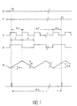
Ce principe est illustré plus précisément à l'aide du chronogramme de la figure 1. On cherche à mesurer l'intervalle de temps tv entre une impulsion de départ D et une impulsion de fin d'intervalle à mesurer F.This principle is illustrated more precisely using the timing diagram of FIG. 1. We seek to measure the time interval t v between a start pulse D and an end pulse to measure F.
Pour cela, on utilise une horloge de base H, de période T. On compte le nombre n d'impulsions d'horloge qui sont suivies par une période entière T, et ceci pendant la durée tv. Le temps total correspondant à l'écoulement de cette période est égal à nT. Comme l'horloge n'est pas synchrone avec le signal de départ D et de fin F, il faut en outre déterminer d'une part le temps t₁, qui s'écoule entre le signal de départ D et le début de la première impulsion d'horloge qui commence après D, et, d'autre part, le temps t₂, qui s'écoule entre le signal de fin F et la fin de la dernière période d'horloge qui s'achève avant le signal F. Pour obtenir la durée de l'intervalle de temps tv, il suffit ensuite d'additionner les trois temps mesurés : t₁+nT+t₂.For this, we use a basic clock H, of period T. We count the number n of clock pulses which are followed by an entire period T, and this for the duration t v . The total time corresponding to the passage of this period is equal to nT. As the clock is not synchronous with the start signal D and end signal F, it is also necessary to determine on the one hand the time t₁, which elapses between the start signal D and the start of the first clock pulse which begins after D, and, on the other hand, the time t₂, which elapses between the end signal F and the end of the last clock period which ends before the signal F. To obtain the duration of the time interval t v , it then suffices to add the three measured times: t₁ + nT + t₂.
Pour déterminer t₁ et t₂, on utilise un signal triangulaire R, de période 2T, d'amplitude A, et synchrone avec l'horloge de base de période T. A tout instant, si a est l'amplitude mesurée sur la rampe, le t écoulé depuis le début de la rampe est égal à ![]()
![]()
En échantillonnant les rampes à l'apparition du signal de départ D et du signal de fin F, on obtient des amplitudes a₁ et a₂ représentatives respectivement de t₁ et t₂.By sampling the ramps on the appearance of the start signal D and the end signal F, we obtain amplitudes a₁ and a₂ representative of t₁ and t₂ respectively.
Si l'impulsion de départ se produit au cours d'une rampe montante, on a alors : t₁=![]()
![]()
Si l'impulsion de départ se produit au cours d'une rampe descendante, on a : t₁=T-![]()
![]()
Si l'impulsion de fin F se produit sur une rampe montante, on a : t₂=![]()
![]()
Si l'impulsion de fin F se produit sur une rampe descendante, on a : t₂=T-![]()
![]()
t₁ et t₂ sont ensuite numérisés, ce qui donne deux valeurs T₁ et T₂ correspondantes. On obtient ensuite la durée de l'intervalle de temps tv=nT+T₁+T₂.t₁ and t₂ are then digitized, which gives two corresponding values T₁ and T₂. We then obtain the duration of the time interval t v = nT + T₁ + T₂.
Un dispositif pour la mise en oeuvre de l'invention est représenté sur la figure 2. Une horloge H délivre des impulsions de période T sur une des entrées d'une porte ET, désignée par la référence 2. Cette horloge H peut être réalisée à partir d'un oscillateur à quartz, fonctionnant par exemple à une fréquence de 200 MHz. L'autre entrée de la porte ET reçoit un signal à partir de la sortie Q d'une bascule RS désignée par la référence 4, sur l'entrée S de laquelle on envoie le signal de départ D, tandis que l'entrée R est pilotée par le signal de fin F. L'ensemble constitué par la porte ET, la bascule 4 et l'horloge H constitue un circuit de mesure numérique permettant d'obtenir une valeur grossière de l'intervalle de temps à mesurer. Cette valeur est égale à nT où n est le nombre de périodes d'horloge T écoulé entre le signal de début D et le signal de fin F. Elle est comptabilisée dans un compteur 3.A device for implementing the invention is shown in FIG. 2. A clock H delivers pulses of period T on one of the inputs of an AND gate, designated by the
En parallèle, une division de la fréquence des signaux de l'horloge H est effectuée par un diviseur 6, constitué par exemple par une bascule, la sortie de ce diviseur alimentant un générateur de rampes 8. Ce générateur peut être réalisé par la charge et la décharge à courant constant d'un condensateur. La période et la pente de ces rampes sont très bien définies. La sortie du générateur de rampes 8 est envoyée sur un convertisseur analogique-numérique rapide 10 (par exemple du type flash ou échantillonneur rapide + convertisseur), dont une autre entrée reçoit un signal provenant par exemple d'une bascule 12, pilotée par les signaux D et F de début et de fin de la période à mesurer. Ainsi, le convertisseur 10 prélève l'information sur l'amplitude de la rampe aux instants de début D et de fin F de l'intervalle de temps à mesurer, ainsi que l'information relative à la parité de la rampe à ces instants, c'est-à-dire à son caractère montant ou descendant. Ce convertisseur permet d'obtenir les informations portant sur les valeurs T₁ et T₂. Ces informations sont mémorisées dans une mémoire 13.In parallel, a division of the frequency of the signals of the clock H is carried out by a divider 6, constituted for example by a rocker, the output of this divider supplying a
L'information grossière portant sur nT et les informations "fines" portant sur les intervalles T₁ et T₂ sont envoyées à un circuit de traitement 14 qui calcule la durée tv de l'intervalle de temps à mesurer.The rough information relating to nT and the “fine” information relating to the intervals T₁ and T₂ are sent to a
Ce dispositif permet d'obtenir une bonne précision, puisqu'il permet de s'affranchir de toute synchronisation des signaux de départ D et de fin F de mesure par rapport à l'horloge H du chronomètre ; il permet également de s'affranchir de la capacité limitée du chronomètre à déterminer un faible et un très important écart temporel, pouvant varier de quelques picosecondes à l'infini, du fait de sa fréquence qui est fixe.This device makes it possible to obtain good accuracy, since it makes it possible to dispense with any synchronization of the start signals D and end signals F of measurement with respect to the clock H of the chronometer; it also overcomes the limited capacity of the chronometer to determine a small and a very large time difference, which can vary from a few picoseconds to infinity, due to its frequency which is fixed.
Ce dispositif permet également de déterminer des intervalles de temps importants avec une précision constante, quelle que soit la durée de cet intervalle de temps. Ceci n'est pas vrai dans le cas des dispositifs de mesure de la durée d'un intervalle de temps selon l'art antérieur, notamment dans le cas du dispositif décrit dans la demande de brevet français n° 93 08145 du 2 juillet 1993. En effet, ce dernier dispositif fait intervenir, en début de mesure de l'intervalle de temps, la décharge d'un condensateur, et en fin de mesure de l'intervalle de temps la charge du même condensateur ; or, la charge mesurée immédiatement après l'arrivée du signal D peut varier avant que l'on ait atteint la partie finale de l'intervalle de temps à mesurer, juste avant le signal de fin F, et ceci d'autant plus que l'intervalle de temps à mesurer est important. Dans le dispositif selon la présente invention, on évite ce problème en ayant recours à des rampes récurrentes.This device also makes it possible to determine large time intervals with constant precision, whatever the duration of this time interval. This is not true in the case of devices for measuring the duration of a time interval according to the prior art, in particular in the case of the device described in French patent application No. 93 08145 of July 2, 1993. Indeed, this latter device involves, at the start of measurement of the time interval, the discharge of a capacitor, and at the end of measurement of the time interval the charge of the same capacitor; however, the charge measured immediately after the arrival of the signal D can vary before the final part of the time interval to be measured is reached, just before the end signal F, and this all the more so since l The time interval to be measured is important. In the device according to the present invention, this problem is avoided by using recurrent ramps.
Enfin, ce type de dispositif peut être facilement intégrable pour réaliser un circuit compact.Finally, this type of device can be easily integrated to make a compact circuit.
Un mode particulier de réalisation de l'invention permet de tenir compte des problèmes liés aux situations d'ambiguïté sur le signal de départ D et sur le signal d'arrivée F. Ces problèmes surgissent lorsque l'un ou l'autre de ces signaux, se produisent simultanément à un front de montée ou de descente des signaux de l'horloge. Le compteur de la partie numérique du dispositif, partie qui détermine la mesure grossière de l'intervalle de temps, peut alors compter une impulsion d'horloge supplémentaire, qui n'aurait pas du être comptée.A particular embodiment of the invention makes it possible to take account of the problems linked to the situations of ambiguity on the starting signal D and on the arrival signal F. These problems arise when one or the other of these signals , occur simultaneously with a rising or falling edge of the clock signals. The counter of the digital part of the device, part which determines the rough measurement of the time interval, can then count an additional clock pulse, which should not have been counted.
De façon à résoudre ce problème, l'invention propose un dispositif qui fonctionne sur le principe illustré sur la figure 3. Conformément à ce qui a déjà été expliqué ci-dessus, une horloge H₁ délivre des signaux de période T. Un diviseur permet de générer des signaux S₁, de période 2T, synchronisés avec les signaux de l'horloge H₁. On peut ainsi générer des rampes montantes et descendantes R₁, d'amplitude A. Un dispositif de retard permet de générer un deuxième signal d'horloge H₂, à partir du signal H₁, les signaux H₂ étant décalés de T/2 par rapport aux signaux de H₁. Ainsi, un front descendant d'un créneau de H₂ correspond à un front montant d'un créneau de H₁, comme on peut le voir sur la figure 3. Ce signal d'horloge H₂ permet de générer, de la même manière qu'il a été expliqué ci-dessus pour l'horloge H₁, un signal S₂ de période 2T, qui va commander lui-même une rampe R₂ de même amplitude A que la rampe R₁. Lorsque le signal D de départ de la mesure se présente, on échantillonne simultanément les deux rampes R₁ et R₂. S'il y a par exemple ambiguïté entre D et H₁, c'est-à-dire si le signal D se superpose à un front de montée d'un créneau de H₁, il ne peut y avoir simultanément ambiguïté entre le signal D et les signaux générés par H₂, du fait du décalage d'une demi-période entre les deux voies. Par conséquent, il suffit d'identifier l'horloge qui n'est pas en situation d'ambiguïté avec le signal de départ D, et de ne retenir alors que la valeur échantillonnée de la rampe R correspondante pour déterminer t₁. Par exemple, si la situation d'ambiguïté se présente entre le signal de départ D et l'horloge H₁, l'horloge valide pour déterminer la mesure de t₁ est l'horloge H₂ et la valeur à prendre en compte est celle mesurée sur la rampe R₂.In order to solve this problem, the invention proposes a device which operates on the principle illustrated in FIG. 3. In accordance with what has already been explained above, a clock H₁ delivers signals of period T. A divider makes it possible to generate signals S₁, of period 2T, synchronized with the signals of the clock H₁. It is thus possible to generate rising and falling ramps R₁, of amplitude A. A delay device makes it possible to generate a second clock signal H₂, from the signal H₁, the signals H₂ being offset by T / 2 relative to the signals from H₁. Thus, a falling edge of a slot of H₂ corresponds to a rising edge of a slot of H₁, as can be seen in FIG. 3. This clock signal H₂ makes it possible to generate, in the same way as it has been explained above for the clock H₁, a signal S₂ of period 2T, which will itself control a ramp R₂ of the same amplitude A as the ramp R₁. When the measurement start signal D occurs, the two ramps R₁ and R₂ are sampled simultaneously. If for example there is ambiguity between D and H₁, that is to say if the signal D is superimposed on a rising edge of a slot of H₁, there cannot be simultaneously ambiguity between the signal D and the signals generated by H₂, due to the offset of a half-period between the two channels. Consequently, it suffices to identify the clock which is not in an ambiguous situation with the starting signal D, and then to retain only the sampled value of the corresponding ramp R to determine t₁. For example, if the ambiguity situation arises between the starting signal D and the clock H₁, the valid clock to determine the measurement of t₁ is the clock H₂ and the value to be taken into account is that measured on the R₂ ramp.
Il en va de même pour toute situation d'ambiguïté sur le signal F. Lorsque le signal de fin F se présente, on échantillonne simultanément les deux rampes R₁ et R₂. On prend pour t₂ la valeur de la rampe R₁ ou R₂ issue de l'horloge H₁ ou H₂ qui ne présente pas d'ambiguïté avec le signal F.The same goes for any ambiguity situation on the signal F. When the end signal F occurs, the two ramps R₁ and R₂ are sampled simultaneously. We take for t₂ the value of the ramp R₁ or R₂ from the clock H₁ or H₂ which does not have any ambiguity with the signal F.
Dans le cas où une situation d'ambiguité existe simultanément sur D et F, il est possible de rajouter un troisième circuit avec une horloge H₃ décalée par rapport à H₂ et H₁.In the case where an ambiguity situation exists simultaneously on D and F, it is possible to add a third circuit with a clock H₃ offset from H₂ and H₁.
Dans le cas où il n'y a aucune ambiguïté, ni avec l'horloge H₁ ni avec l'horloge H₂, les valeurs de temps obtenues (t₁ ou t₂) seront prises indifféremment sur l'un des deux circuits correspondant aux deux horloges.In the case where there is no ambiguity, neither with the clock H₁ nor with the clock H₂, the time values obtained (t₁ or t₂) will be taken indifferently on one of the two circuits corresponding to the two clocks.
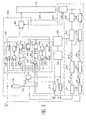
Le dispositif correspondant à ce mode particulier de mise en oeuvre de l'invention est illustré sur la figure 4. Sur cette figure, dans un premier bloc 24, un premier compteur 25 reçoit sur son entrée autorisation CE un ordre de comptage venant d'une bascule 23 et sur son entrée C les signaux d'horloge H₁. Les données en sortie du premier compteur 25 sont transmises à un circuit de traitement 22 par l'intermédiaire d'un circuit d'aiguillage 36 commandé par un circuit OU 32.The device corresponding to this particular embodiment of the invention is illustrated in FIG. 4. In this figure, in a
Les bascules D 26 et 30 reçoivent les signaux D et F par l'intermédiaire d'une fonction OU 40, 41 sur leur entrée D. La bascule 23, qui délivre le signal d'autorisation CE est également commandée par les signaux D et F tous deux retardés d'une quantité voisine de 3 temps de propagation dans des portes par les dispositifs 19, 42 qui sont constitués par exemple de retards dans des portes logiques. Le premier circuit ET 27 réalise la fonction ET de la sortie de la bascule 26 et de l'horloge H₂ ; les signaux de cette dernière sont obtenus à partir de H₁ et d'un circuit de retard 18, constitué par exemple par des temps de propagation dans des portes.The D flip-
Dans le second bloc 28, un second compteur 29 reçoit sur son entrée autorisation CE un ordre de comptage venant de la bascule 23. Les données de ce compteur 29 sont transmises au circuit de traitement 22 par l'intermédiaire du circuit 36. La seconde bascule de type D 30 fonctionne comme décrit ci-dessus. Le second circuit ET 31 réalise la fonction ET entre la sortie du circuit 30 et l'horloge H₁.In the second block 28, a
La sortie du circuit 32 commande le fonctionnement du circuit d'aiguillage 36 pour obtenir la lecture du compteur 25 ou 29 dont la bascule de type D (26 ou 30) associée n'a pas basculé la première. Il détecte la première des bascules 26 ou 30 qui a basculé et il autorise la lecture du compteur dont la bascule n'a pas changé d'état.The output of the
S'il y a une situation d'incertitude, par exemple au début du comptage, pour l'un ou l'autre des compteurs, le premier des circuits d'identification de présence 26, 30 qui bascule valide le choix entre les horloges H₁ ou H₂. Le compteur validé est laissé inchangé, par contre l'autre compteur est remis à zéro avant l'arrivée de la deuxième impulsion d'horloge suivant le signal D. Ceci est réalisé par les circuits 44, 45 et 46, 47 respectivement pour les premier et deuxième compteurs. Les circuits 44 et 46 sont des circuits ET, les circuits 45 et 47 sont des mises en forme temporelle.If there is a situation of uncertainty, for example at the start of the counting, for one or other of the counters, the first of the
Une bascule 33 (bascule de type RS) reçoit sur son entrée SET la sortie d'un circuit OU 34 dont les entrées correspondent aux signaux D et F retardés par les circuits 42 et 19. La bascule 33 reçoit sur son autre entrée les sorties des deux portes ET 27, 31.A flip-flop 33 (RS type flip-flop) receives on its SET input the output of an
Cette bascule 33 commande une entrée d'un convertisseur analogique-numérique 50 et une entrée d'un convertisseur analogique-numérique 52. Une autre entrée de chacun de ces convertisseurs 50, 52 est reliée à l'horloge H₁ (respectivement H₂) par l'intermédiaire d'une bascule 51 (respectivement 53) qui permet de générer un signal S₁ respectivement S₂ de période 2T, et d'un générateur de rampe 55 (respectivement 57) pour générer une rampe R1 (respectivement R2) . En aval des convertisseurs analogiques-numériques, on trouve deux mémoires 60, 62 et un circuit d'aiguillage 56 commandé par le circuit 32.This flip-
Claims (8)
Applications Claiming Priority (2)
| Application Number | Priority Date | Filing Date | Title |
|---|---|---|---|
| FR9411848A FR2725326B1 (en) | 1994-10-04 | 1994-10-04 | DEVICE FOR MEASURING THE DURATION OF A TIME INTERVAL |
| FR9411848 | 1994-10-04 |
Publications (2)
| Publication Number | Publication Date |
|---|---|
| EP0706100A1 true EP0706100A1 (en) | 1996-04-10 |
| EP0706100B1 EP0706100B1 (en) | 1998-08-12 |
Family
ID=9467553
Family Applications (1)
| Application Number | Title | Priority Date | Filing Date |
|---|---|---|---|
| EP95402202A Expired - Lifetime EP0706100B1 (en) | 1994-10-04 | 1995-10-02 | Time interval measuring device |
Country Status (4)
| Country | Link |
|---|---|
| US (1) | US5717659A (en) |
| EP (1) | EP0706100B1 (en) |
| DE (1) | DE69504000T2 (en) |
| FR (1) | FR2725326B1 (en) |
Cited By (1)
| Publication number | Priority date | Publication date | Assignee | Title |
|---|---|---|---|---|
| CN110737189A (en) * | 2019-11-05 | 2020-01-31 | 中国电子科技集团公司第四十四研究所 | Pulse laser interval measuring circuit |
Families Citing this family (3)
| Publication number | Priority date | Publication date | Assignee | Title |
|---|---|---|---|---|
| JP3451576B2 (en) | 1996-09-20 | 2003-09-29 | 株式会社日立製作所 | Information processing system |
| US7843771B2 (en) * | 2007-12-14 | 2010-11-30 | Guide Technology, Inc. | High resolution time interpolator |
| CN112506031B (en) * | 2020-11-30 | 2021-09-21 | 中国计量科学研究院 | High-precision time interval measuring system for laser interference fringe signals |
Citations (3)
| Publication number | Priority date | Publication date | Assignee | Title |
|---|---|---|---|---|
| DE2422727A1 (en) * | 1973-05-11 | 1974-12-05 | Suwa Seikosha Kk | ELECTRONIC CLOCK |
| US4912734A (en) * | 1989-02-14 | 1990-03-27 | Ail Systems, Inc. | High resolution event occurrance time counter |
| US5200933A (en) * | 1992-05-28 | 1993-04-06 | The United States Of America As Represented By The United States Department Of Energy | High resolution data acquisition |
Family Cites Families (3)
| Publication number | Priority date | Publication date | Assignee | Title |
|---|---|---|---|---|
| JP2568145Y2 (en) * | 1992-08-14 | 1998-04-08 | 株式会社アドバンテスト | Signal time difference measuring device |
| FR2707814B1 (en) * | 1993-07-02 | 1995-09-01 | Commissariat Energie Atomique | Device for measuring the duration of a time interval. |
| US5325340A (en) * | 1993-07-29 | 1994-06-28 | Ramsey Alexander W | Pacing device |
-
1994
- 1994-10-04 FR FR9411848A patent/FR2725326B1/en not_active Expired - Fee Related
-
1995
- 1995-09-21 US US08/531,377 patent/US5717659A/en not_active Expired - Fee Related
- 1995-10-02 EP EP95402202A patent/EP0706100B1/en not_active Expired - Lifetime
- 1995-10-02 DE DE69504000T patent/DE69504000T2/en not_active Expired - Fee Related
Patent Citations (3)
| Publication number | Priority date | Publication date | Assignee | Title |
|---|---|---|---|---|
| DE2422727A1 (en) * | 1973-05-11 | 1974-12-05 | Suwa Seikosha Kk | ELECTRONIC CLOCK |
| US4912734A (en) * | 1989-02-14 | 1990-03-27 | Ail Systems, Inc. | High resolution event occurrance time counter |
| US5200933A (en) * | 1992-05-28 | 1993-04-06 | The United States Of America As Represented By The United States Department Of Energy | High resolution data acquisition |
Cited By (1)
| Publication number | Priority date | Publication date | Assignee | Title |
|---|---|---|---|---|
| CN110737189A (en) * | 2019-11-05 | 2020-01-31 | 中国电子科技集团公司第四十四研究所 | Pulse laser interval measuring circuit |
Also Published As
| Publication number | Publication date |
|---|---|
| EP0706100B1 (en) | 1998-08-12 |
| FR2725326A1 (en) | 1996-04-05 |
| DE69504000T2 (en) | 1999-02-25 |
| US5717659A (en) | 1998-02-10 |
| FR2725326B1 (en) | 1996-10-25 |
| DE69504000D1 (en) | 1998-09-17 |
Similar Documents
| Publication | Publication Date | Title |
|---|---|---|
| EP2238471B1 (en) | 3d active imaging device | |
| EP0891654B1 (en) | Apparatus and method for measuring time intervals with very high resolution | |
| FR2624802A1 (en) | ENCODING THE VALUE OF MULTIPLE MEASUREMENTS IN A TIRE | |
| FR2468153A1 (en) | TIMING SYSTEM | |
| FR2598570A1 (en) | DIGITAL TIMER CIRCUIT | |
| EP0002415B1 (en) | Method and device for counting transmission errors in a digital radio relay link | |
| EP0165144A1 (en) | Electronic high-resolution chronometric system | |
| EP1521143A1 (en) | Time to Digital Converter | |
| EP0194924A1 (en) | Detection of a pulse train in noise and its use in a DME radionavigation system | |
| EP0706100B1 (en) | Time interval measuring device | |
| FR2510809A1 (en) | ELECTRONIC CONTROL MOUNT FOR PRODUCING MONOSTABLE BEHAVIOR IN A BISTABLE RELAY | |
| EP0793153B1 (en) | Precision time interval measurement system and laser telemetric device comprising such system | |
| EP0197801A2 (en) | Method and device for quickly setting the phase of a clock signal at a predetermined value | |
| EP0632279A1 (en) | Appliance for measuring the duration of a time interval | |
| EP2327160A1 (en) | Analog counter, and imager incorporating such a counter | |
| US5196741A (en) | Recycling ramp interpolator | |
| EP0051531B1 (en) | Apparatus for the precise dating of an event with regard to a time reference | |
| EP0729082B1 (en) | Very precise chrono-measurement of an event | |
| FR2750495A1 (en) | METHOD AND DEVICE FOR MEASURING A FLOW OF FLOWING FLUID | |
| EP0012056B1 (en) | Telemetry device and use thereof in a tracking radar | |
| US5132558A (en) | Recycling ramp interpolator | |
| EP0574287A2 (en) | Re-settable dead time circuit | |
| EP2446534B1 (en) | Very high precision device for measuring the time a signal is input | |
| EP1390769B1 (en) | High-frequency electrical signal sampling device | |
| FR3113950A1 (en) | Frequency measurement |
Legal Events
| Date | Code | Title | Description |
|---|---|---|---|
| PUAI | Public reference made under article 153(3) epc to a published international application that has entered the european phase |
Free format text: ORIGINAL CODE: 0009012 |
|
| AK | Designated contracting states |
Kind code of ref document: A1 Designated state(s): BE DE GB IT LU |
|
| 17P | Request for examination filed |
Effective date: 19960920 |
|
| GRAG | Despatch of communication of intention to grant |
Free format text: ORIGINAL CODE: EPIDOS AGRA |
|
| 17Q | First examination report despatched |
Effective date: 19971013 |
|
| GRAG | Despatch of communication of intention to grant |
Free format text: ORIGINAL CODE: EPIDOS AGRA |
|
| GRAH | Despatch of communication of intention to grant a patent |
Free format text: ORIGINAL CODE: EPIDOS IGRA |
|
| GRAH | Despatch of communication of intention to grant a patent |
Free format text: ORIGINAL CODE: EPIDOS IGRA |
|
| GRAA | (expected) grant |
Free format text: ORIGINAL CODE: 0009210 |
|
| AK | Designated contracting states |
Kind code of ref document: B1 Designated state(s): BE DE GB IT LU |
|
| REF | Corresponds to: |
Ref document number: 69504000 Country of ref document: DE Date of ref document: 19980917 |
|
| PG25 | Lapsed in a contracting state [announced via postgrant information from national office to epo] |
Ref country code: LU Free format text: LAPSE BECAUSE OF NON-PAYMENT OF DUE FEES Effective date: 19981002 |
|
| PG25 | Lapsed in a contracting state [announced via postgrant information from national office to epo] |
Ref country code: BE Free format text: LAPSE BECAUSE OF NON-PAYMENT OF DUE FEES Effective date: 19981031 |
|
| GBT | Gb: translation of ep patent filed (gb section 77(6)(a)/1977) |
Effective date: 19981014 |
|
| BERE | Be: lapsed |
Owner name: COMMISSARIAT A L'ENERGIE ATOMIQUE Effective date: 19981031 |
|
| PLBE | No opposition filed within time limit |
Free format text: ORIGINAL CODE: 0009261 |
|
| STAA | Information on the status of an ep patent application or granted ep patent |
Free format text: STATUS: NO OPPOSITION FILED WITHIN TIME LIMIT |
|
| 26N | No opposition filed | ||
| REG | Reference to a national code |
Ref country code: GB Ref legal event code: IF02 |
|
| PGFP | Annual fee paid to national office [announced via postgrant information from national office to epo] |
Ref country code: GB Payment date: 20040929 Year of fee payment: 10 |
|
| PGFP | Annual fee paid to national office [announced via postgrant information from national office to epo] |
Ref country code: DE Payment date: 20041023 Year of fee payment: 10 |
|
| PG25 | Lapsed in a contracting state [announced via postgrant information from national office to epo] |
Ref country code: IT Free format text: LAPSE BECAUSE OF NON-PAYMENT OF DUE FEES;WARNING: LAPSES OF ITALIAN PATENTS WITH EFFECTIVE DATE BEFORE 2007 MAY HAVE OCCURRED AT ANY TIME BEFORE 2007. THE CORRECT EFFECTIVE DATE MAY BE DIFFERENT FROM THE ONE RECORDED. Effective date: 20051002 Ref country code: GB Free format text: LAPSE BECAUSE OF NON-PAYMENT OF DUE FEES Effective date: 20051002 |
|
| PG25 | Lapsed in a contracting state [announced via postgrant information from national office to epo] |
Ref country code: DE Free format text: LAPSE BECAUSE OF NON-PAYMENT OF DUE FEES Effective date: 20060503 |
|
| GBPC | Gb: european patent ceased through non-payment of renewal fee |
Effective date: 20051002 |