EP0632279A1 - Appliance for measuring the duration of a time interval - Google Patents
Appliance for measuring the duration of a time interval Download PDFInfo
- Publication number
- EP0632279A1 EP0632279A1 EP94401492A EP94401492A EP0632279A1 EP 0632279 A1 EP0632279 A1 EP 0632279A1 EP 94401492 A EP94401492 A EP 94401492A EP 94401492 A EP94401492 A EP 94401492A EP 0632279 A1 EP0632279 A1 EP 0632279A1
- Authority
- EP
- European Patent Office
- Prior art keywords
- circuit
- clock
- signal
- interval
- input
- Prior art date
- Legal status (The legal status is an assumption and is not a legal conclusion. Google has not performed a legal analysis and makes no representation as to the accuracy of the status listed.)
- Withdrawn
Links
Images


Classifications
-
- G—PHYSICS
- G01—MEASURING; TESTING
- G01R—MEASURING ELECTRIC VARIABLES; MEASURING MAGNETIC VARIABLES
- G01R29/00—Arrangements for measuring or indicating electric quantities not covered by groups G01R19/00 - G01R27/00
- G01R29/02—Measuring characteristics of individual pulses, e.g. deviation from pulse flatness, rise time or duration
- G01R29/027—Indicating that a pulse characteristic is either above or below a predetermined value or within or beyond a predetermined range of values
- G01R29/0273—Indicating that a pulse characteristic is either above or below a predetermined value or within or beyond a predetermined range of values the pulse characteristic being duration, i.e. width (indicating that frequency of pulses is above or below a certain limit)
Definitions
- the invention relates to a device for measuring the duration of a time interval.
- the field of the invention is that of a precise time measurement, of the order of a few tens of picoseconds of resolution, for very long measured time intervals, for example of the order of a microsecond, this measurement being performed quickly.
- Averaging is only possible if the phenomenon measured has suitable stationarity relative to the averaging time.
- successive events differ and the speed of the measurement determines the frequency of acquisition of the images; it is therefore important that it be rapid (duration of the measurement ⁇ 8 ⁇ s ⁇ frequency ⁇ 125 kHz).
- duration of the measurement ⁇ 8 ⁇ s ⁇ frequency ⁇ 125 kHz.
- a French patent application No. 8,905,654 filed on April 28, 1989 describes a telemetry method by measuring time of flight and a device for implementing the method.
- the time measurement is made according to the interpolation-expansion method.
- the implementation of this method does not include a device making it possible to avoid the counting error of a clock stroke in certain situations of ambiguity.
- the duration of the measurement is 10 microseconds without counting the calculation and conversion times.
- the object of the invention is to provide a precise measurement device for large measured time intervals.
- the analog measurement circuit includes a storage circuit and voltage amplitude conversion followed by an analog / digital conversion circuit.
- the first counter receives on its CE authorization input a counting order coming from the RS type flip-flop, the data at the output of the first counter are transmitted to the processing circuit via a switching circuit controlled by an OR circuit, the first D type flip-flop receives the end of interval signal F on its D input and the first clock on its clock input, the first AND circuit performs the AND function of the output of the first rocker of type D and the second clock.
- the first counter receives on its CE authorization input a counting order coming from the type RS flip-flop.
- the data at the output of the first counter are transmitted to the processing circuit via a switching circuit controlled by an OR circuit.
- the first D type flip-flop controlled by a first OR circuit, receives the start signal and the interval end signal on its D input and the first clock on its clock input.
- the first AND circuit performs the AND function of the output of the first D-type flip-flop and the second clock.
- the second counter receives on its CE authorization input a counting order coming from the RS type flip-flop, the data of this counter are transmitted to the processing circuit via a circuit the second type D flip-flop receives the end of interval signal on its D input and the second clock on its clock input.
- the second AND circuit performs the AND function between the output of this flip-flop D and the first clock.
- the second counter receives on its authorization input a counting order coming from the RS type flip-flop.
- the data from this counter is transmitted to the processing circuit via a routing circuit.
- the second D type flip-flop controlled by a second OR circuit, receives the start signal and the interval end signal on its D input and the second clock on its clock input.
- the second AND circuit performs the AND function between the output of this flip-flop D and the first clock.
- the circuit with a memory has its output which controls the operation of the switching circuit to obtain the reading of the counter whose associated D type flip-flop did not switch first.
- This circuit is linked by a flip-flop to the processing circuit and supplies it with the data relating to the selected counter. It detects the first of the D type flip-flops which has switched over and authorizes the reading of the counter whose D-type flip-flop has not changed state.
- This flip-flop is an RS-type flip-flop which receives on its SET input the signal for the end of the delayed interval, and on its RESET input an OR circuit connected to the outputs of the AND circuits. Its output delivers a signal to the storage circuit and conversion into voltage amplitude.
- the signal at the end of the interval is delayed by a sufficiently long duration relative to the unit propagation time of the operators used to ensure that the clock takes into account the clock of each of the counting channels between the counter and the flip-flop D associated.
- this duration must advantageously remain short compared to the clock period.
- the device of the invention can be used for example for producing an image sensor for robotics which requires a large number of precise measurements per second, so-called "flight time” measurements, of a laser pulse, the time to be measured being that taken by a light pulse to come and go from a transmitter to a receiver having undergone a reflection on a target (flight time).
- the device of the invention measures the coarse part of the time interval digitally, and the fine part analogically. The parameters thus acquired are combined to obtain the result.
- the time measurement is thus obtained by associating a digital quantity in the form of a number of counted clock periods, and an analog quantity by the conversion of a time into voltage amplitude.
- the measuring device of the invention shown in FIG. 1 therefore comprises a digital measuring circuit 10 receiving these pulses D and F at the start and end of the interval, one of the outputs of which is connected directly to a circuit of processing 12, and the other output of which is connected to this circuit 12 through an analog measurement circuit 11.
- the clock signal pulses H are counted in a counter, the signal F stops the counter and triggers a voltage ramp 15 which is itself stopped by the front edge of the pulse of the clock signal according to signal F.
- signal F occurs randomly with respect to the clock signal.
- the CE signal is the validation signal of the clock pulse counter.
- equation (1) makes it possible to obtain K by means of an analog / digital conversion; equation (2) gives the time expressed on the basis of the clock period.
- the analog quantity V is obtained by switching a current in a capacitor for a time KT.
- the desired numerical quantity is obtained in the counter.
- the width of the signals D and F is between 1/2 and a clock period so as to have a probability of coincidence of the clock front and the signals equal to one. If the signals are too narrow, one of them F or D (or both) may not be counted.
- the device of the invention shown in FIG. 3, comprises two channels for counting two clock signals C1 and C2 of the same frequency, shifted in time by half a period (delay circuit 18).
- the measurement result taken into account is that of the path where it could not have been ambiguous.
- the instant of presence of the signal F is shifted on the circuits which it controls.
- This device comprises: a digital circuit 20, an analog circuit 21 and a processing circuit 22.
- the digital circuit 20 is provided with a first clock C1 and a second clock C2, whose pulses are offset by a half-period T relative to those of the first clock C1.
- the first counter 25 receives on its CE authorization input a counting order coming from the flip-flop 23.
- the data at the output of the first counter 25 is transmitted to the processing circuit 22 via a routing circuit 36 controlled by an OR circuit 32.
- the first D type flip-flop 26 receives the signal F on its D input and the first clock C1 on its clock input.
- the first AND circuit 27 performs the AND function of the output of the flip-flop 26 and of the clock C2.
- the second counter 29 receives on its CE authorization input a counting order coming from the flip-flop 23.
- the data from this counter 29 is transmitted to the processing circuit 22 via the circuit 36.
- the second flip-flop D type 30 receives the signal F on its D input and the second clock C2 on its clock input.
- the second AND circuit 31 performs the AND function between the output of this circuit 30 and the clock C1.
- the circuit 32 has its output which controls the operation of the switching circuit 36 to obtain the reading of the counter 25 or 29, of which the associated D type flip-flop (26 or 30) did not switch first. It detects the first of the flip-flops 26 or 30 which has rocked. It authorizes the reading of the counter whose rocker has not changed state.
- the circuit 36 is connected by a rocker 33 to the processing circuit 22 and supplies it with the data relating to the selected counter.
- the analog measurement circuit 21 comprises a circuit 34 for memorizing and converting into voltage amplitude followed by an analog / digital conversion circuit 35.
- This analog measurement circuit 21 is controlled by the flip-flop 33, capable of measuring the time separating the end of delay signal from the clock pulse which follows it.
- the circuit 35 makes it possible to convert the analog data obtained at the output of the circuit 34 into digital data.
- the duration of the signal at the output of flip-flop 33 represents the fine part of the time interval that one seeks to measure.
- This flip-flop 33 controls the circuit 34 by triggering the voltage rise ramp V.
- the flip-flop 33 is a flip-flop RS which receives on its input SET the delayed signal F, on its input RESET an OR connected to the outputs of the AND circuits 27 and 31. Its output delivers a signal which controls the circuit 34 and which is stopped by the 'next clock pulse C1 or C2 (previously selected clock).
- the processing circuit 22 receives on the one hand the data of the selected counter 25 or 29, and on the other hand the output signal of the flip-flop 33, converted into a voltage via the circuit 34, which is digitized by the circuit 35.
- this device 35 is based on the use of a controlled time offset between the actions of the end of delay signal F on the counter and an ambiguity identification circuit in each of the channels.
- the two counters 25 and 29 respectively receive the clock signals C1 and C2 on their counting inputs, and a signal on their CE authorization inputs.
- the four flip-flops 26, 30, 33 and 23 of type D are equipped with SET-RESET controls.
- the flip-flops 26 and 30 receive the clocks C1, C2 and the signal F on their inputs D. Their outputs are respectively mixed on two AND circuits 27 and 31 with the clock signals C2, C1.
- the CE authorization input of the meters is controlled by the signal F delayed for example by about 3tpd (propagation time). Assuming a situation of uncertainty on the counter 29 between CE and C2, such a situation cannot exist simultaneously on the taking into account of the signal F by C2 on flip-flop 30 due to this time shift of 3tpd. Thus, the flip-flop 30 is activated. The clock signal C1 stops the circuit 34 via the AND circuit 31. The counter 25, which has worked outside any situation of uncertainty, is then read.
- the circuits used have propagation times, anticipation / holding times which are taken into account for the positioning of the signals.
- the counters 25 and 29 are reset to zero before each measurement by a conventional device (not shown).
- the data contained in the processing circuit 22 is transferred to units such as, for example, calculation and measurement management units.
- the dual nature of the two measurement channels is affirmed in the topology, the placement and the distribution of the circuits in the boxes.
- the latches 26 and 30 are located in the same housing.
- the clock signals C1, C2 which control them, therefore pass through the same number of operators in identical housings. Any thermal drift is thus differentially compensated.
- Some circuits are used as delay and signal redistribution elements.
- the paths of the two clock signals are identical in terms of copper length and of operators crossed.
- the lines are all with defined impedance 50 or 100 ohms and adapted with respect to their characteristic impedance, in order to avoid oscillation and reflection phenomena.
- the time / voltage amplitude conversion slope is adjusted so that one can process in the same binary word the content of the counter and the result of the analog / digital conversion of the output V of the time / voltage amplitude converter.
- the content of each counter is a binary word whose least significant bit (or LSB) represents for example ten nanoseconds.
- the result of the digital conversion from the conversion of time to amplitude is a binary word.
- the conversion slope of the converter 34 to V / ns is adjusted so that the most significant bit (or MSB) of the word of this converter represents for example five nanoseconds.
- the combination of the two digital and analog measurements which makes it possible to count large time intervals without any other limitation than that of the capacity of a digital memory, presents no ambiguity and makes it possible to achieve the results of the measurements obtained for short time intervals.
- the precision over time is linked to the resolution of the converter 35: in a “careful” embodiment of the device, it is possible to reach ten picoseconds, the performance of the best current instruments.
- This measurement of the time interval duration finds its application in the production of an image sensor for robotics which requires a large number of precise measurements per second, so-called "flight time” measurements, of a pulse. laser.
- the time to be measured is that taken by a light pulse to go back and forth from a transmitter to a receiver having undergone a reflection on a target (flight time).
- the time measurement circuit is then intended to be adapted to a range finder.
- the time is measured with an accuracy of 20 picoseconds in a laser shot at the rate of one point of the image per measurement.
- Tmesure round trip time + processing time (dead time).
- the image is not stationary, a laser shot per pixel is carried out.
- the device of the invention is materialized on an electronic card of 3 dm2, six electrical layers with connections adapted to defined impedance.
- the start signals D and end F of the time interval to be measured are neither referenced to a clock signal, as illustrated in the figure 4.
- the signal D triggers a discharge of the capacity of the circuit 34, which is stopped by one of the clock pulses C1 or C2.
- the counters are then authorized.
- the first of the presence identification circuits 26 or 30 which switches valid the choice between the clocks C1 or C2 to stop the discharge of the capacity and the counter which counted the first clock pulse reliably.
- V2 corresponds to the amplitude reached by the analog device corresponding to F2 and V1 to F1.
- the start (D) and end (F) signals of the time interval to be measured are neither referenced to the clock signal as illustrated in FIG. 4.
- the D flip-flops 26 and 30 now receive the D or F signals via an OR function 40, 41 on their D input.
- the flip-flop 23 which delivers the CE authorization signal is also controlled by the D and F signals both delayed by an amount close to 3tpd (19, 42).
- the capacity of the circuit 34 is associated with two equal current generators and of opposite signs controlled by the flip-flops 33 and 43 which are triggered respectively by the signals D and F.
- the signal D triggers a discharge of the capacity which is stopped by the one of the clock pulses C1 or C2. The counters are then authorized.
- the first of the presence identification circuits 26, 30 which switches validates the choice between clocks C1 or C2 to stop the discharge of the capacity and the counter which has counted the first clock pulse reliably.
- circuits 44, 45 and 46, 47 respectively for the first and second counters.
- Circuits 44 and 46 are AND circuits, circuits 45 and 47 are time formatting.
- the signal F triggers a charging of the capacitor with a current mirror of the current used prior to the discharge. As in the previous device, it stops the counters by identifying which one should be read.
- the capacity is the site of a discharge corresponding to the time preceding the start of the validated counting, therefore to be added to the time represented by the content N of the counter.
- this capacity is the seat of a charge corresponding to the time which precedes the N plus the first pulse of the clock signal, that is to say to subtract from the content of the counter.
- the capacity integrates these functions provided that its charge has not varied between the two discharge / charge phases.
Abstract
Description
L'invention concerne un dispositif de mesure de la durée d'un intervalle de temps.The invention relates to a device for measuring the duration of a time interval.
Le domaine de l'invention est celui d'une mesure de temps précise, de l'ordre de quelques dizaines de picosecondes de résolution, pour des intervalles de temps mesurés très grands, par exemple de l'ordre de la microseconde, cette mesure étant effectuée rapidement.The field of the invention is that of a precise time measurement, of the order of a few tens of picoseconds of resolution, for very long measured time intervals, for example of the order of a microsecond, this measurement being performed quickly.
Dans le domaine de la mesure de temps de grande précision, on fait appel à des techniques de moyennage ou d'autres procédés qui augmentent considérablement le temps d'acquisition de la valeur de la mesure par rapport au temps mesuré.In the field of high-precision time measurement, use is made of averaging techniques or other methods which considerably increase the time for acquiring the value of the measurement compared to the measured time.
Le moyennage n'est possible que si le phénomène mesuré présente une stationnarité convenable relativement au temps de moyennage.Averaging is only possible if the phenomenon measured has suitable stationarity relative to the averaging time.
L'utilisation d'un vemier de fréquence tel que décrit dans l'article intitulé "The Vemier Time-Measuring Technique" de Robert G. Baron (Proceedings of the Ire, janvier 1957) recherche un battement et ainsi rallonge d'une quantité non négligeable le temps de mesure (5 microsecondes de temps de mesure pour une résolution de 20 picosecondes avec des horloges de 100 Megahertz). Ceci a pour effet de limiter le nombre de mesures possibles bien en deçà de la cadence de réalisation de certains événements.The use of a frequency vemier as described in the article entitled "The Vemier Time-Measuring Technique" by Robert G. Baron (Proceedings of the Ire, January 1957) searches for a beat and thus lengthens an amount not negligible the measurement time (5 microseconds of measurement time for a resolution of 20 picoseconds with clocks of 100 Megahertz). This has the effect of limiting the number of possible measurements well below the rate at which certain events take place.
Par ailleurs, les systèmes purement analogiques sont peu adaptés à la mesure de grands intervalles de temps, en raison de l'instabilité de la mémoire utilisée de tels intervalles (≧100ns), ou de la détérioration du signal pour les systèmes à circulation et coïncidence.Furthermore, purely analog systems are not well suited to measuring large time intervals, due to the instability of the memory used for such intervals (≧ 100 ns), or the deterioration of the signal for circulation and coincidence systems. .
Dans le domaine de l'invention des événements successifs diffèrent et la vitesse de la mesure détermine la fréquence d'acquisition des images ; il est alors important qu'elle soit rapide (durée de la mesure ≦8µs→ fréquence≧ 125 kHz). Dans tous les cas, postérieurement à l'acquisition des paramètres de la mesure, il y a un calcul à réaliser qui nécessite un temps propre, qui peut être relativement indépendant de la technique de mesure située en amont. La fréquence de répétition dépend ainsi de la méthode de mesure du temps et de la conversion du résultat.In the field of the invention, successive events differ and the speed of the measurement determines the frequency of acquisition of the images; it is therefore important that it be rapid (duration of the measurement ≦ 8µs → frequency ≧ 125 kHz). In all cases, after the acquisition of the measurement parameters, there is a calculation to be performed which requires its own time, which can be relatively independent of the measurement technique located upstream. The repetition frequency thus depends on the time measurement method and the conversion of the result.
Un état de la technique antérieure est donné dans l'article intitulé "Review of Sub-Nanosecond Time-Internal Measurements" de Dan I. Porat (Stanford University).A state of the art is given in the article entitled "Review of Sub-Nanosecond Time-Internal Measurements" by Dan I. Porat (Stanford University).
Une demande de brevet français n°8 905 654 déposée le 28 Avril 1989 décrit un procédé de télémétrie par mesure de temps de vol et un dispositif pour la mise en oeuvre du procédé. La mesure de temps est faite selon la méthode d'interpolation-dilatation. La mise en application de ce procédé ne comprend pas de dispositif permettant d'éviter l'erreur de comptage d'un coup d'horloge dans certaines situations d'ambiguïté. Par ailleurs, la durée de la mesure est de 10 microsecondes sans compter les temps de calcul et de conversion.A French patent application No. 8,905,654 filed on April 28, 1989 describes a telemetry method by measuring time of flight and a device for implementing the method. The time measurement is made according to the interpolation-expansion method. The implementation of this method does not include a device making it possible to avoid the counting error of a clock stroke in certain situations of ambiguity. Furthermore, the duration of the measurement is 10 microseconds without counting the calculation and conversion times.
L'objet de l'invention est de proposer un dispositif de mesure précise pour de grands intervalles de temps mesurés.The object of the invention is to provide a precise measurement device for large measured time intervals.
L'invention concerne un dispositif de mesure de la durée d'un intervalle de temps entre un signal de début et un signal de fin d'intervalle à mesurer comprenant :
- un circuit numérique muni d'une horloge, apte à compter le nombre d'impulsions d'horloge comprises entre le signal de début et le coup d'horloge succédant au signal de fin d'intervalle ;
- un circuit analogique, apte à mesurer le temps séparant le signal de début d'intervalle de l'impulsion d'horloge qui lui succède et à mesurer le temps séparant le signal de fin d'intervalle de l'impulsion d'horloge qui lui succède et apte à convertir les données analogiques obtenus en données numériques ;
- un circuit de traitement, apte à déterminer la durée de l'intervalle de temps à partir des données fournies par le circuit numérique et celles fournies par le circuit analogique préalablement converties en données numériques ;
caractérisé en ce que le circuit numérique est muni d'une seconde horloge, dont les impulsions sont décalées d'une demi-période T par rapport à celles de la première horloge et des moyens aptes à déterminer lequel des comptages réalisés sur l'une des deux horloges est à prendre en compte de manière à résoudre toute situation d'ambiguïté qui pourrait conduire à une erreur de comptage d'une période d'horloge.The invention relates to a device for measuring the duration of a time interval between a start signal and an end signal of an interval to be measured, comprising:
- a digital circuit provided with a clock, capable of counting the number of clock pulses comprised between the start signal and the clock stroke succeeding the end of interval signal;
- an analog circuit, able to measure the time separating the interval start signal from the clock pulse which follows it and to measure the time separating the end of interval signal from the clock pulse which succeeds and is able to convert the analog data obtained into digital data;
- a processing circuit, capable of determining the duration of the time interval from the data supplied by the digital circuit and that supplied by the analog circuit previously converted into digital data;
characterized in that the digital circuit is provided with a second clock, the pulses of which are offset by half a period T relative to those of the first clock and means capable of determining which of the counts made on one of the two clocks must be taken into account in order to resolve any ambiguity that could lead to an error in counting a clock period.
Dans une première réalisation, le signal de début d'intervalle est synchrone de la première horloge et le circuit numérique comprend :
- une bascule de type RS commandée par le signal de départ D sur son entrée SET, et par le signal de fin d'intervalle F retardé, après passage dans un circuit retardateur, sur son entrée RESET ;
- un premier bloc comportant :
- · un premier compteur,
- · une première bascule de type D,
- · un premier circuit ET ;
- un second bloc comportant :
- · un second compteur,
- · une seconde bascule de type D,
- · un second circuit ET ;
- un circuit doté d'une mémoire, apte à effectuer une fonction OU pour détecter laquelle d'entre les sorties des bascules a basculé la première.
- an RS type flip-flop controlled by the start signal D on its SET input, and by the end of interval signal F delayed, after passing through a delay circuit, on its RESET input;
- a first block comprising:
- · A first counter,
- · A first D-type rocker,
- · A first AND circuit;
- a second block comprising:
- · A second counter,
- · A second D-type rocker,
- · A second AND circuit;
- a circuit provided with a memory, capable of performing an OR function for detecting which of the outputs of the flip-flops has switched first.
Dans une seconde réalisation, le signal de début d'intervalle n'est pas synchrone de la première horloge, et le circuit numérique comprend :
- une bascule de type RS commandée par le signal de début retardé après passage dans un premier circuit retardateur sur son entrée SET, et par le signal de fin d'intervalle retardé, après passage dans un circuit retardateur de retard identique à celui du premier circuit retardateur sur son entrée RESET ;
- un premier bloc comportant :
- · un premier compteur,
- · une première bascule de type D,
- · un premier circuit ET,
- · un premier circuit OU,
- · un second circuit ET,
- · un moyen de mise en forme temporelle du signal ;
- un second bloc comportant :
- · un second compteur,
- · une seconde bascule de type D,
- · un troisième circuit ET,
- · un second circuit OU,
- · un quatrième circuit ET,
- · un moyen de mise en forme temporelle du signal ;
- un circuit doté d'une mémoire, apte à effectuer une fonction OU pour détecter laquelle d'entre les sorties des bascules a basculé la première.
- an RS-type flip-flop controlled by the delayed start signal after passing through a first delay circuit on its SET input, and by the delayed interval end signal, after passing through a delay delay circuit identical to that of the first delay circuit on its RESET input;
- a first block comprising:
- · A first counter,
- · A first D-type rocker,
- · A first AND circuit,
- · A first OR circuit,
- · A second AND circuit,
- · A means of temporal shaping of the signal;
- a second block comprising:
- · A second counter,
- · A second D-type rocker,
- · A third AND circuit,
- · A second OR circuit,
- · A fourth AND circuit,
- · A means of temporal shaping of the signal;
- a circuit provided with a memory, capable of performing an OR function for detecting which of the outputs of the flip-flops has switched first.
Le circuit de mesure analogique comprend un circuit de mémorisation et de conversion en amplitude de tension suivi d'un circuit de conversion analogique/numérique.The analog measurement circuit includes a storage circuit and voltage amplitude conversion followed by an analog / digital conversion circuit.
Dans la première réalisation, dans le premier bloc, le premier compteur reçoit sur son entrée autorisation CE un ordre de comptage venant de la bascule de type RS, les données en sortie du premier compteur sont transmises au circuit de traitement par l'intermédiaire d'un circuit aiguillage commandé par un circuit OU, la première bascule de type D reçoit le signal de fin d'intervalle F sur son entrée D et la première horloge sur son entrée horloge, le premier circuit ET réalise la fonction ET de la sortie de la première bascule de type D et de la seconde horloge.In the first embodiment, in the first block, the first counter receives on its CE authorization input a counting order coming from the RS type flip-flop, the data at the output of the first counter are transmitted to the processing circuit via a switching circuit controlled by an OR circuit, the first D type flip-flop receives the end of interval signal F on its D input and the first clock on its clock input, the first AND circuit performs the AND function of the output of the first rocker of type D and the second clock.
Dans la seconde réalisation, dans le premier bloc, le premier compteur reçoit sur son entrée autorisation CE un ordre de comptage venant de la bascule de type RS. Les données en sortie du premier compteur sont transmises au circuit de traitement par l'intermédiaire d'un circuit aiguillage commandé par un circuit OU. La première bascule de type D, commandée par un premier circuit OU reçoit le signal de début et le signal de fin d'intervalle sur son entrée D et la première horloge sur son entrée horloge. Le premier circuit ET réalise la fonction ET de la sortie de la première bascule de type D et de la seconde horloge.In the second embodiment, in the first block, the first counter receives on its CE authorization input a counting order coming from the type RS flip-flop. The data at the output of the first counter are transmitted to the processing circuit via a switching circuit controlled by an OR circuit. The first D type flip-flop, controlled by a first OR circuit, receives the start signal and the interval end signal on its D input and the first clock on its clock input. The first AND circuit performs the AND function of the output of the first D-type flip-flop and the second clock.
Dans la première réalisation, dans le second bloc, le second compteur reçoit sur son entrée autorisation CE un ordre de comptage venant de la bascule de type RS, les données de ce compteur sont transmises au circuit de traitement par l'intermédiaire d'un circuit d'aiguillage, la seconde bascule de type D reçoit le signal de fin d'intervalle sur son entrée D et la seconde horloge sur son entrée horloge. Le second circuit ET réalise la fonction ET entre la sortie de cette bascule D et la première horloge.In the first embodiment, in the second block, the second counter receives on its CE authorization input a counting order coming from the RS type flip-flop, the data of this counter are transmitted to the processing circuit via a circuit the second type D flip-flop receives the end of interval signal on its D input and the second clock on its clock input. The second AND circuit performs the AND function between the output of this flip-flop D and the first clock.
Dans la seconde réalisation, dans le second bloc, le second compteur reçoit sur son entrée autorisation un ordre de comptage venant de la bascule de type RS. Les données de ce compteur sont transmises au circuit de traitement par l'intermédiaire d'un circuit d'aiguillage. La seconde bascule de type D, commandée par un second circuit OU reçoit le signal de début et le signal de fin d'intervalle sur son entrée D et la seconde horloge sur son entrée horloge. Le second circuit ET réalise la fonction ET entre la sortie de cette bascule D et la première horloge.In the second embodiment, in the second block, the second counter receives on its authorization input a counting order coming from the RS type flip-flop. The data from this counter is transmitted to the processing circuit via a routing circuit. The second D type flip-flop, controlled by a second OR circuit, receives the start signal and the interval end signal on its D input and the second clock on its clock input. The second AND circuit performs the AND function between the output of this flip-flop D and the first clock.
Le circuit doté d'une mémoire a sa sortie qui commande le fonctionnement du circuit aiguillage pour obtenir la lecture du compteur dont la bascule de type D associée n'a pas basculée la première. Ce circuit est relié par une bascule au circuit de traitement et lui fournit les données relatives au compteur sélectionné. Il détecte la première des bascules de type D qui a basculé et autorise la lecture du compteur dont la bascule de type D n'a pas changé d'état. Cette bascule est une bascule de type RS qui reçoit sur son entrée SET le signal de fin d'intervalle retardé, et sur son entrée RESET un circuit OU connecté aux sorties des circuits ET. Sa sortie délivre un signal au circuit de mémorisation et de conversion en amplitude de tension.The circuit with a memory has its output which controls the operation of the switching circuit to obtain the reading of the counter whose associated D type flip-flop did not switch first. This circuit is linked by a flip-flop to the processing circuit and supplies it with the data relating to the selected counter. It detects the first of the D type flip-flops which has switched over and authorizes the reading of the counter whose D-type flip-flop has not changed state. This flip-flop is an RS-type flip-flop which receives on its SET input the signal for the end of the delayed interval, and on its RESET input an OR circuit connected to the outputs of the AND circuits. Its output delivers a signal to the storage circuit and conversion into voltage amplitude.
Dans la première réalisation, le circuit analogique comporte un circuit de mémorisation qui comprend :
- deux générateurs aptes à fournir des courants égaux en amplitude et de signes opposés ;
- un condensateur ;
- deux interrupteurs aptes à commuter les courants issus des deux générateurs sur le condensateur et qui sont commandés par la bascule de type RS, recevant le signal de fin d'intervalle retardé sur son entrée SET et le signal de début d'intervalle sur entrée RESET.
- two generators capable of supplying currents equal in amplitude and of opposite signs;
- a capacitor;
- two switches able to switch the currents from the two generators on the capacitor and which are controlled by the RS type flip-flop, receiving the delayed end of interval signal on its SET input and the interval start signal on RESET input.
Dans la seconde réalisation, le circuit analogique comporte un circuit de mémorisation qui comprend :
- deux générateurs aptes à fournir des courants égaux en amplitude et de signes opposés ;
- un condensateur ;
- deux interrupteurs aptes à commuter les courants issus des deux générateurs sur le condensateur et qui sont commandés par les bascules de type RS, et recevant pour la première, le signal de fin d'intervalle retardé sur son entrée SET et le signal OU connecté sur son entrée RESET et pour la deuxième, le signal de début d'intervalle retardé sur son entrée SET et le OU connecté sur son entrée RESET.
- two generators capable of supplying currents equal in amplitude and of opposite signs;
- a capacitor;
- two switches capable of switching the currents from the two generators to the capacitor and which are controlled by flip-flops of the RS type, and receiving for the first time the end of interval signal delayed on its SET input and the OR signal connected on its RESET input and for the second, the delay start signal delayed on its SET input and the OR connected on its RESET input.
Le signal de fin d'intervalle est retardé d'une durée suffisamment grande par rapport au temps de propagation unitaire des opérateurs utilisés pour assurer un décalage de prise en compte par l'horloge de chacune des voies de comptage entre le compteur et la bascule D associée. D'autre part, cette durée doit avantageusement demeurer courte devant la période d'horloge.The signal at the end of the interval is delayed by a sufficiently long duration relative to the unit propagation time of the operators used to ensure that the clock takes into account the clock of each of the counting channels between the counter and the flip-flop D associated. On the other hand, this duration must advantageously remain short compared to the clock period.
Par exemple, le signal de fin d'intervalle F est retardé d'un délai de 3tpd (tpd=temps de propagation).For example, the end of interval signal F is delayed by a delay of 3tpd (tpd = propagation time).
Il en est de même pour le signal de début d'intervalle, dans la seconde variante.The same is true for the signal at the start of the interval, in the second variant.
Le dispositif de l'invention peut être utilisé par exemple pour la réalisation d'un capteur d'images pour la robotique qui requiert un grand nombre de mesures précises par seconde, mesures dites de "temps de vol", d'une impulsion laser, le temps à mesurer étant celui mis par une impulsion lumineuse pour aller et venir d'un émetteur à un récepteur en ayant subi une réflexion sur une cible (temps de vol).The device of the invention can be used for example for producing an image sensor for robotics which requires a large number of precise measurements per second, so-called "flight time" measurements, of a laser pulse, the time to be measured being that taken by a light pulse to come and go from a transmitter to a receiver having undergone a reflection on a target (flight time).
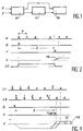
- Les figures 1 à 3 illustrent le dispositif de l'invention, et le fonctionnement de celui-ci ;Figures 1 to 3 illustrate the device of the invention, and the operation thereof;
- la figure 4 illustre le fonctionnement d'une variante du dispositif de l'invention ;Figure 4 illustrates the operation of a variant of the device of the invention;
- la figure 5 illustre une variante de réalisation du dispositif de l'invention.FIG. 5 illustrates an alternative embodiment of the device of the invention.
Pour mesurer la durée d'un intervalle de temps déterminé, le dispositif de l'invention mesure la partie grossière de l'intervalle de temps de manière numérique, et la partie fine de manière analogique. Les paramètres ainsi acquis sont recombinés pour obtenir le résultat. La mesure de temps est ainsi obtenue en associant une grandeur numérique sous la forme d'un nombre de périodes d'horloge comptées, et une grandeur analogique par la conversion d'un temps en amplitude de tension.To measure the duration of a determined time interval, the device of the invention measures the coarse part of the time interval digitally, and the fine part analogically. The parameters thus acquired are combined to obtain the result. The time measurement is thus obtained by associating a digital quantity in the form of a number of counted clock periods, and an analog quantity by the conversion of a time into voltage amplitude.
Le dispositif de mesure de l'invention, représenté à la figure 1 comprend donc un circuit de mesure numérique 10 recevant ces impulsions D et F de début et de fin d'intervalle, dont l'une des sorties est reliée directement à un circuit de traitement 12, et dont l'autre sortie est reliée à ce circuit 12 au travers d'un circuit de mesure analogique 11.The measuring device of the invention, shown in FIG. 1 therefore comprises a
Sur le diagramme de fonctionnement du dispositif de l'invention, représenté sur la figure 2, on a l'impulsion de départ D, synchrone d'un signal d'horloge H récurrent d'impulsions de période T et l'impulsion de fin d'intervalle à mesurer F.On the operating diagram of the device of the invention, represented in FIG. 2, there is the start pulse D, synchronous with a clock signal H recurrent of pulses of period T and the end pulse d interval to be measured F.
Dès le front avant de l'impulsion D, les impulsions de signal horloge H sont comptées dans un compteur, le signal F arrête le compteur et déclenche une rampe de tension 15 qui est elle-même arrêtée par le front avant de l'impulsion du signal horloge suivant le signal F. On note que, à la différence du signal D, le signal F survient de manière aléatoire par rapport au signal horloge. Le signal CE est le signal de validation du compteur d'impulsions horloge. L'amplitude V atteinte par la rampe correspond à une fraction K de la période T, telle que :![]()
Si le contenu du compteur est N, l'expression de la durée de l'intervalle de temps cherché est :![]()
![]()
If the content of the counter is N, the expression of the duration of the sought time interval is: ![]()
La saisie des grandeurs V et N est faite en temps réel pendant la mesure, I'équation (1) permet d'obtenir K par l'intermédiaire d'une conversion analogique/numérique ; l'équation (2) donne le temps exprimé sur la base de la période horloge. La grandeur analogique V est obtenue par commutation d'un courant dans une capacité pendant un temps KT. La grandeur numérique désirée est obtenue dans le compteur.The quantities V and N are entered in real time during the measurement, equation (1) makes it possible to obtain K by means of an analog / digital conversion; equation (2) gives the time expressed on the basis of the clock period. The analog quantity V is obtained by switching a current in a capacitor for a time KT. The desired numerical quantity is obtained in the counter.
La largeur des signaux D et F est comprise entre 1/2 et une période d'horloge de façon à avoir une probabilité de coïncidence du front d'horloge et des signaux égale à un. Si les signaux sont trop étroits, l'un d'entre eux F ou D (voire les deux) risque de ne pas être comptabilisé.The width of the signals D and F is between 1/2 and a clock period so as to have a probability of coincidence of the clock front and the signals equal to one. If the signals are too narrow, one of them F or D (or both) may not be counted.
En ce qui concerne le résultat de l'acquisition numérique on peut faire les observations suivantes: lorsque les signaux F et H sont présents simultanément, le compteur peut compter l'impulsion d'horloge alors que le signal F aurait dû l'interdire. Il y a une situation d'ambiguïté qui peut conduire à une erreur d'une période d'horloge.With regard to the result of the digital acquisition, the following observations can be made: when the signals F and H are present simultaneously, the counter can count the clock pulse whereas the signal F should have prohibited it. There is an ambiguity that can lead to a clock period error.
De façon à éviter cette ambiguïté. Le dispositif de l'invention, représenté sur la figure 3, comprend deux voies de comptage de deux signaux horloge C1 et C2 de même fréquence, décalés en temps d'une demi-période (circuit retard 18). Le résultat de mesure pris en compte est celui de la voie où il n'y a pas pu avoir ambiguïté. En outre dans chaque voie on décale l'instant de présence du signal F (circuit retard 19) sur les circuits qu'il commande.In order to avoid this ambiguity. The device of the invention, shown in FIG. 3, comprises two channels for counting two clock signals C1 and C2 of the same frequency, shifted in time by half a period (delay circuit 18). The measurement result taken into account is that of the path where it could not have been ambiguous. In addition, in each channel, the instant of presence of the signal F (delay circuit 19) is shifted on the circuits which it controls.
Ce dispositif comprend : un circuit numérique 20, un circuit analogique 21 et un circuit de traitement 22.This device comprises: a
Le circuit numérique 20 est muni d'une première horloge C1 et d'une seconde horloge C2, dont les impulsions sont décalées d'une demi-période T par rapport à celles de la première horloge C1.The
Ce circuit numérique 20 comprend également :
- une bascule de
type RS 23, commandée par le signal de départ D sur son entrée SET, et par le signal de fin d'intervalle F retardé, après passage dans lecircuit 19, sur son entrée RESET ; - un
premier bloc 24 comportant :- · un premier compteur 25,
- · une première bascule de
type D 26, - · un
premier circuit ET 27 ;
- un
second bloc 28 comportant :- · un
second compteur 29, - · une seconde bascule de
type D 30, - · un
second circuit ET 31 ;
- · un
un circuit 32 doté d'une mémoire, apte à effectuer une fonction OU pour détecter laquelle d'entre les sorties descircuits 26 et 30 a basculé la première.
- an
RS 23 flip-flop, controlled by the start signal D on its SET input, and by the end of interval signal F delayed, after passing throughcircuit 19, on its RESET input; - a
first block 24 comprising:- A
first counter 25, - A
first D 26 type scale, - · A first AND
circuit 27;
- A
- a
second block 28 comprising:- A
second counter 29, - A
second D 30 type rocker, - · A second AND
circuit 31;
- A
- a
circuit 32 with a memory, capable of performing an OR function to detect which of the outputs ofcircuits
Dans le premier bloc 24, le premier compteur 25 reçoit sur son entrée autorisation CE un ordre de comptage venant de la bascule 23. Les données en sortie du premier compteur 25 sont transmises au circuit de traitement 22 par l'intermédiaire d'un circuit aiguillage 36 commandé par un circuit OU 32. La première bascule de type D 26 reçoit le signal F sur son entrée D et la première horloge C1 sur son entrée horloge. Le premier circuit ET 27 réalise la fonction ET de la sortie de la bascule 26 et de l'horloge C2.In the
Dans le second bloc 28, le second compteur 29 reçoit sur son entrée autorisation CE un ordre de comptage venant de la bascule 23. Les données de ce compteur 29 sont transmises au circuit de traitement 22 par l'intermédiaire du circuit 36. La seconde bascule de type D 30 reçoit le signal F sur son entrée D et la seconde horloge C2 sur son entrée horloge. Le second circuit ET 31 réalise la fonction ET entre la sortie de ce circuit 30 et l'horloge C1.In the
Le circuit 32 a sa sortie qui commande le fonctionnement du circuit aiguillage 36 pour obtenir la lecture du compteur 25 ou 29 dont la bascule de type D (26 ou 30) associée n'a pas basculée la première. Il détecte la première des bascules 26 ou 30 qui a basculé. Il autorise la lecture du compteur dont la bascule n'a pas changé d'état. Le circuit 36 est relié par une bascule 33 au circuit de traitement 22 et lui fournit les données relatives au compteur sélectionné.The
Le circuit de mesure analogique 21 comprend un circuit 34 de mémorisation et de conversion en amplitude de tension suivi d'un circuit de conversion analogique/numérique 35.The
Ce circuit de mesure analogique 21 est commandé par la bascule 33, apte à mesurer le temps séparant le signal de fin de délai de l'impulsion d'horloge qui lui succède. Le circuit 35 permet de convertir les données analogiques obtenues en sortie du circuit 34 en données numériques. La durée du signal à la sortie de la bascule 33 représente la partie fine de l'intervalle de temps que l'on cherche à mesurer. Cette bascule 33 commande le circuit 34 en déclenchant la rampe de montée en tension V.This
La bascule 33 est une bascule RS qui reçoit sur son entrée SET le signal F retardé, sur son entrée RESET un OU connecté aux sorties des circuits ET 27 et 31. Sa sortie délivre un signal qui commande le circuit 34 et qui est arrêté par l'impulsion d'horloge suivante C1 ou C2 (horloge préalablement sélectionnée).The flip-
Le circuit de traitement 22 reçoit d'une part les données du compteur 25 ou 29 sélectionné, et d'autre part le signal de sortie de la bascule 33, converti en une tension par l'intermédiaire du circuit 34, qui est numérisée par le circuit 35.The
Le fonctionnement de ce dispositif 35 est basé sur l'utilisation d'un décalage temporel contrôlé entre les actions du signal de fin de délai F sur le compteur et d'un circuit d'identification d'ambiguïté dans chacune des voies.The operation of this
Les deux compteurs 25 et 29 reçoivent respectivement les signaux horloge C1 et C2 sur leurs entrées de comptage, et un signal sur leurs entrées d'autorisation CE. Les quatre bascules 26, 30, 33 et 23 de type D sont dotées de contrôles SET-RESET.The two
Les bascules 26 et 30 reçoivent les horloges C1, C2 et le signal F sur leurs entrées D. Leurs sorties sont respectivement mélangées sur deux circuits ET 27 et 31 avec les signaux horloge C2, C1.The flip-
L'entrée autorisation CE des compteurs est commandée par le signal F retardé par exemple d'environ 3tpd (temps de propagation). En supposant une situation d'incertitude sur le compteur 29 entre CE et C2, une telle situation ne peut exister simultanément sur la prise en compte du signal F par C2 sur la bascule 30 du fait de ce décalage temporel de 3tpd. Ainsi, la bascule 30 est activée. Le signal horloge C1 arrête le circuit 34 par l'intermédiaire du circuit ET 31. Le compteur 25, qui a travaillé en dehors de toute situation d'incertitude, est alors lu.The CE authorization input of the meters is controlled by the signal F delayed for example by about 3tpd (propagation time). Assuming a situation of uncertainty on the
Dans une situation analogue sur le compteur 25, le circuit 34 est arrêté par C2 et le compteur 29 est lu.In a similar situation on the
Par ailleurs, quand il y a une situation d'incertitude sur l'un ou l'autre des circuits 26 ou 30, il en résulte un état métastable, c'est-à-dire un état indéfini variant de 0 à 1, sur sa sortie qui ne dure pas plus de quelques nanosecondes (<<T/2). C'est alors le circuit qui travaille avec l'horloge duale décalée d'une demi-période qui est activé et réalise l'aiguillage.Furthermore, when there is a situation of uncertainty on one or other of
Ces conditions de fonctionnement sont garanties par un contrôle très précis des temps de propagation des signaux. Les circuits utilisés ont des temps de propagation, des temps d'anticipation/maintien qui sont pris en compte pour le positionnement des signaux.These operating conditions are guaranteed by very precise control of the signal propagation times. The circuits used have propagation times, anticipation / holding times which are taken into account for the positioning of the signals.
Une remise à zéro des compteurs 25 et 29 est réalisée avant chaque mesure par un dispositif classique (non représenté).The
Après chaque mesure les données contenues dans le circuit de traitement 22 sont transférées vers des unités comme par exemple des unités de calcul et de gestion des mesures.After each measurement, the data contained in the
Le caractère dual des deux voies de mesure est affirmé dans la topologie, le placement et la répartition des circuits dans les boîtiers. Avantageusement les bascules 26 et 30 sont situées dans un même boîtier. Les signaux horloge C1, C2 qui les commandent, traversent donc le même nombre d'opérateurs dans des boîtiers identiques. Toute dérive thermique est ainsi différentielle ment compensée. Certains circuits sont utilisés comme éléments de retard et de redistribution du signal. Les parcours des deux signaux horloge sont identiques en terme de longueur de cuivre et d'opérateurs traversés. Les lignes sont toutes à impédance définie 50 ou 100 ohms et adaptées par rapport à leur impédance caractéristique, afin d'éviter des phénomènes d'oscillation et de réflexion. Moyennant ce contrôle précis des temps dans les circuits logiques très grande vitesse utilisés, (fréquence de l'ordre du gigahertz), et des liaisons entre les circuits, on évite toute erreur sur la saisie des paramètres de la mesure.The dual nature of the two measurement channels is affirmed in the topology, the placement and the distribution of the circuits in the boxes. Advantageously, the
Dans une réalisation avantageuse la pente de conversion temps/amplitude de tension est réglée de manière à ce que l'on puisse traiter dans le même mot binaire le contenu du compteur et le résultat de la conversion analogique/numérique de la sortie V du convertisseur temps/amplitude de tension. Le contenu de chaque compteur est un mot binaire dont le bit le moins significatif (ou LSB) représente par exemple dix nanosecondes. Le résultat de la conversion numérique de la conversion du temps en amplitude est un mot binaire. On règle la pente de conversion du convertisseur 34 en V/ns de telle sorte que le bit le plus significatif (ou MSB) du mot de ce convertisseur représente par exemple cinq nanosecondes. Ainsi les deux mots numériques sont adjacents et le temps d'accès au résultat est pratiquement égal au temps de conversion.In an advantageous embodiment, the time / voltage amplitude conversion slope is adjusted so that one can process in the same binary word the content of the counter and the result of the analog / digital conversion of the output V of the time / voltage amplitude converter. The content of each counter is a binary word whose least significant bit (or LSB) represents for example ten nanoseconds. The result of the digital conversion from the conversion of time to amplitude is a binary word. The conversion slope of the
Par ailleurs, la combinaison des deux mesures numérique et analogique, qui permet de compter des intervalles de temps grands sans autre limitation que celle de la capacité d'une mémoire numérique, ne présente aucune ambiguïté et permet d'atteindre les résultats des mesures obtenues pour des intervalles de temps courts. La précision sur le temps est liée à la résolution du convertisseur 35 : dans une réalisation "soignée" du dispositif on peut atteindre une dizaine de picosecondes, performance des meilleurs instruments actuels.Furthermore, the combination of the two digital and analog measurements, which makes it possible to count large time intervals without any other limitation than that of the capacity of a digital memory, presents no ambiguity and makes it possible to achieve the results of the measurements obtained for short time intervals. The precision over time is linked to the resolution of the converter 35: in a “careful” embodiment of the device, it is possible to reach ten picoseconds, the performance of the best current instruments.
Cette mesure de la durée d'intervalle de temps trouve son application dans la réalisation d'un capteur d'images pour la robotique qui requiert un grand nombre de mesures précises par seconde, mesures dites de "temps de vol", d'une impulsion laser. Le temps à mesurer est celui mis par une impulsion lumineuse pour aller et revenir d'un émetteur à un récepteur en ayant subi une réflexion sur une cible (temps de vol). On travaille alors sur l'impulsion électrique correspondant à l'impulsion lumineuse. Le circuit de mesure de temps est alors destiné à être adapté à un télémètre. Le temps est mesuré avec une précision de 20 picosecondes en un tir laser à raison d'un point de l'image par mesure. On a la relation Tmesure = durée aller/retour + temps de traitement (temps mort). L'image n'étant pas stationnaire, on effectue un tir laser par pixel.This measurement of the time interval duration finds its application in the production of an image sensor for robotics which requires a large number of precise measurements per second, so-called "flight time" measurements, of a pulse. laser. The time to be measured is that taken by a light pulse to go back and forth from a transmitter to a receiver having undergone a reflection on a target (flight time). We then work on the electrical pulse corresponding to the light pulse. The time measurement circuit is then intended to be adapted to a range finder. The time is measured with an accuracy of 20 picoseconds in a laser shot at the rate of one point of the image per measurement. We have the relationship Tmesure = round trip time + processing time (dead time). The image is not stationary, a laser shot per pixel is carried out.
A titre d'exemple numérique, avec un temps de conversion analogique/numérique de 100 nanosecondes on peut mesurer des temps de l'ordre de la microseconde avec une précision de 40 picosecondes et une récurrence voisine du mégahertz. Dans la réalisation d'un imageur à trois dimensions pour la robotique mobile, le dispositif de l'invention est matérialisé sur une carte électronique de 3 dm², six couches électriques avec des liaisons adaptées à impédance définie.As a digital example, with an analog / digital conversion time of 100 nanoseconds, we can measure times on the order of a microsecond with an accuracy of 40 picoseconds and a recurrence close to megahertz. In the production of a three-dimensional imager for mobile robotics, the device of the invention is materialized on an electronic card of 3 dm², six electrical layers with connections adapted to defined impedance.
Dans une variante de réalisation de l'invention, les signaux de début D et de fin F de l'intervalle de temps à mesurer ne sont, ni l'un ni l'autre, référencés à un signal horloge, comme illustré sur la figure 4. Le signal D déclenche une décharge de la capacité du circuit 34, qui est arrêtée par l'une des impulsions d'horloge C1 ou C2. Les compteurs sont alors autorisés. De même que dans la description ci-dessus, si il y a une situation d'incertitude quant au début de comptage pour l'un ou l'autre des compteurs, le premier des circuits d'identification de présence 26 ou 30 qui bascule valide le choix entre les horloges C1 ou C2 pour arrêter la décharge de la capacité et le compteur qui a compté la première impulsion d'horloge de façon fiable.In an alternative embodiment of the invention, the start signals D and end F of the time interval to be measured are neither referenced to a clock signal, as illustrated in the figure 4. The signal D triggers a discharge of the capacity of the
Sur la courbe F, on a représenté deux situations de fin d'intervalle repérée par les positions F1 et F2. Sur la courbe V, V2 correspond à l'amplitude atteinte par le dispositif analogique correspondant à F2 et V1 à F1.On the curve F, two situations of end of interval have been represented, identified by the positions F1 and F2. On the curve V, V2 corresponds to the amplitude reached by the analog device corresponding to F2 and V1 to F1.
Ainsi dans cette variante de réalisation, on effectue une mesure de temps sans référence temporelle de départ.Thus in this alternative embodiment, a time measurement is carried out without starting time reference.
Les signaux de début (D) et fin (F) de l'intervalle de temps à mesurer ne sont ni l'un ni l'autre référencés au signal horloge comme illustré sur la figure 4.The start (D) and end (F) signals of the time interval to be measured are neither referenced to the clock signal as illustrated in FIG. 4.
De manière à pouvoir résoudre toute situation d'incertitude sur le signal D comme cela a été fait pour le signal F, le signal D est traité de la même manière par les mêmes opérateurs. On a ainsi la variante de réalisation représentée sur la figure 5.So as to be able to resolve any situation of uncertainty on the signal D as has been done for the signal F, the signal D is treated in the same way by the same operators. There is thus the variant embodiment shown in FIG. 5.
Les bascules D 26 et 30 reçoivent désormais les signaux D ou F par l'intermédiaire d'une fonction OU 40, 41 sur leur entrée D. La bascule 23 qui délivre le signal d'autorisation CE est également commandée par les signaux D et F tous deux retardés d'une quantité voisine de 3tpd (19, 42).The D flip-
La capacité du circuit 34 est associée à deux générateurs de courant égaux et de signes opposés commandés par les bascules 33 et 43 qui sont déclenchées respectivement par les signaux D et F. Le signal D déclenche une décharge de la capacité qui est arrêtée par l'une des impulsions d'horloge C₁ ou C₂. Les compteurs sont alors autorisés.The capacity of the
Comme dans la description précédente, s'il y a une situation d'incertitude au début du comptage pour l'un ou l'autre des compteurs, le premier des circuits d'identification de présence 26, 30 qui bascule valide le choix entre les horloges C₁ ou C₂ pour arrêter la décharge de la capacité et le compteur qui a compté la première impulsion d'horloge de façon fiable.As in the previous description, if there is a situation of uncertainty at the start of counting for one or other of the counters, the first of the
Le compteur validé est laissé inchangé, par contre l'autre compteur est remis à zéro avant l'arrivée de la deuxième impulsion d'horloge suivant le signal D; ainsi son contenu est fiabilisé. Ceci est réalisé par les circuits 44, 45 et 46, 47 respectivement pour les premier et deuxième compteurs. Les circuits 44 et 46 sont des circuits ET, les circuits 45 et 47 sont des mises en forme temporelle.The validated counter is left unchanged, on the other hand the other counter is reset to zero before the arrival of the second clock pulse according to the signal D; thus its content is made reliable. This is achieved by
Le signal F déclenche une charge de la capacité avec un courant miroir du courant utilisé préalablement à la décharge. Comme dans le dispositif précédent, il arrête les compteurs en identifiant lequel doit être lu.The signal F triggers a charging of the capacitor with a current mirror of the current used prior to the discharge. As in the previous device, it stops the counters by identifying which one should be read.
La valeur du temps mesuré est donné par l'équation![]()
Si le compteur validé n'est pas le même lors du traitement des signaux D et F, I'équation à utiliser devient :![]()
![]()
If the validated counter is not the same when processing signals D and F, the equation to be used becomes: ![]()
Dès l'arrivée du signal D, la capacité est le siège d'une décharge correspondant au temps précédant le début du comptage validé, donc à ajouter au temps représenté par le contenu N du compteur. Après l'arrivée du signal F cette capacité est le siège d'une charge correspondant au temps qui précède la N plus unième impulsion du signal horloge, c'est-à-dire à soustraire au contenu du compteur. La capacité intègre ces fonctions sous réserve que sa charge n'ait pas varié entre les deux phases décharge/charge.As soon as the signal D arrives, the capacity is the site of a discharge corresponding to the time preceding the start of the validated counting, therefore to be added to the time represented by the content N of the counter. After the arrival of the signal F, this capacity is the seat of a charge corresponding to the time which precedes the N plus the first pulse of the clock signal, that is to say to subtract from the content of the counter. The capacity integrates these functions provided that its charge has not varied between the two discharge / charge phases.
Claims (15)
Applications Claiming Priority (2)
| Application Number | Priority Date | Filing Date | Title |
|---|---|---|---|
| FR9308145A FR2707814B1 (en) | 1993-07-02 | 1993-07-02 | Device for measuring the duration of a time interval. |
| FR9308145 | 1993-07-02 |
Publications (1)
| Publication Number | Publication Date |
|---|---|
| EP0632279A1 true EP0632279A1 (en) | 1995-01-04 |
Family
ID=9448856
Family Applications (1)
| Application Number | Title | Priority Date | Filing Date |
|---|---|---|---|
| EP94401492A Withdrawn EP0632279A1 (en) | 1993-07-02 | 1994-06-30 | Appliance for measuring the duration of a time interval |
Country Status (3)
| Country | Link |
|---|---|
| US (1) | US5570326A (en) |
| EP (1) | EP0632279A1 (en) |
| FR (1) | FR2707814B1 (en) |
Cited By (1)
| Publication number | Priority date | Publication date | Assignee | Title |
|---|---|---|---|---|
| EP0793153A1 (en) * | 1996-03-01 | 1997-09-03 | Commissariat A L'energie Atomique | Precision time interval measurement system |
Families Citing this family (8)
| Publication number | Priority date | Publication date | Assignee | Title |
|---|---|---|---|---|
| FR2725326B1 (en) * | 1994-10-04 | 1996-10-25 | Commissariat Energie Atomique | DEVICE FOR MEASURING THE DURATION OF A TIME INTERVAL |
| US5745442A (en) * | 1996-10-22 | 1998-04-28 | Power Spectra, Inc. | Digital time interval measurement engine for a time of flight system |
| JP3048962B2 (en) * | 1997-06-20 | 2000-06-05 | 日本電気アイシーマイコンシステム株式会社 | Time measuring method and time measuring system |
| US6687750B1 (en) * | 1999-04-14 | 2004-02-03 | Cisco Technology, Inc. | Network traffic visualization |
| US6456959B1 (en) * | 1999-07-14 | 2002-09-24 | Guide Technology, Inc. | Time interval analyzer having parallel counters |
| DE102005039662A1 (en) * | 2005-08-22 | 2007-03-22 | Asm Automation Sensorik Messtechnik Gmbh | position sensor |
| US7880454B2 (en) * | 2007-12-21 | 2011-02-01 | L&L Engineering Llc | Methods and systems for control of switches in power regulators/power amplifiers |
| CN104133367B (en) * | 2014-07-07 | 2017-02-01 | 中国电子科技集团公司第四十一研究所 | Circuit and method for extracting time interval parameters of clock signals to be measured |
Citations (2)
| Publication number | Priority date | Publication date | Assignee | Title |
|---|---|---|---|---|
| EP0077075A1 (en) * | 1981-10-14 | 1983-04-20 | Hitachi, Ltd. | Digital player for reproducing a digital signal sequence |
| EP0448182A1 (en) * | 1987-09-01 | 1991-09-25 | Sundstrand Data Control, Inc. | Sampling time determining apparatus and method |
Family Cites Families (4)
| Publication number | Priority date | Publication date | Assignee | Title |
|---|---|---|---|---|
| US4164648A (en) * | 1978-06-23 | 1979-08-14 | Hewlett-Packard Company | Double vernier time interval measurement using triggered phase-locked oscillators |
| US4234881A (en) * | 1978-09-28 | 1980-11-18 | Motorola, Inc. | Dynamic digital time interval discriminator and method |
| US4786861A (en) * | 1987-09-01 | 1988-11-22 | Sundstrand Data Control, Inc. | Frequency counting apparatus and method |
| US5200933A (en) * | 1992-05-28 | 1993-04-06 | The United States Of America As Represented By The United States Department Of Energy | High resolution data acquisition |
-
1993
- 1993-07-02 FR FR9308145A patent/FR2707814B1/en not_active Expired - Fee Related
-
1994
- 1994-06-14 US US08/259,714 patent/US5570326A/en not_active Expired - Fee Related
- 1994-06-30 EP EP94401492A patent/EP0632279A1/en not_active Withdrawn
Patent Citations (2)
| Publication number | Priority date | Publication date | Assignee | Title |
|---|---|---|---|---|
| EP0077075A1 (en) * | 1981-10-14 | 1983-04-20 | Hitachi, Ltd. | Digital player for reproducing a digital signal sequence |
| EP0448182A1 (en) * | 1987-09-01 | 1991-09-25 | Sundstrand Data Control, Inc. | Sampling time determining apparatus and method |
Non-Patent Citations (2)
| Title |
|---|
| BARON: "the vernier time-measuring tecnique", PROCEEDINGS OF THE IRE, vol. 45, 1957, NEW YORK,US, pages 21 - 30, XP011155192 * |
| PORAT: "review of sub-nanosecond time interval measurements", IEEE TRANSACTIONS ON NUCLEAR SCIENCE, vol. NS-20, no. 5, October 1973 (1973-10-01), pages 36 - 51, XP002252913, DOI: doi:10.1109/TNS.1973.4327349 * |
Cited By (3)
| Publication number | Priority date | Publication date | Assignee | Title |
|---|---|---|---|---|
| EP0793153A1 (en) * | 1996-03-01 | 1997-09-03 | Commissariat A L'energie Atomique | Precision time interval measurement system |
| FR2745668A1 (en) * | 1996-03-01 | 1997-09-05 | Commissariat Energie Atomique | DEVICE FOR PRECISE MEASUREMENT OF THE DURATION OF A TIME INTERVAL |
| US5912728A (en) * | 1996-03-01 | 1999-06-15 | Commissariat A L'energie Atomique | Device for precisely measuring the duration of a time interval |
Also Published As
| Publication number | Publication date |
|---|---|
| US5570326A (en) | 1996-10-29 |
| FR2707814A1 (en) | 1995-01-20 |
| FR2707814B1 (en) | 1995-09-01 |
Similar Documents
| Publication | Publication Date | Title |
|---|---|---|
| EP2238471B1 (en) | 3d active imaging device | |
| EP1782099B1 (en) | Determining range in 3d imaging systems | |
| CH648929A5 (en) | CAPACITIVE MOVEMENT MEASURING DEVICE. | |
| FR2606144A1 (en) | DIODE THERMOMETER | |
| EP0632279A1 (en) | Appliance for measuring the duration of a time interval | |
| EP0762145B1 (en) | Gamma particle pulse processing system for CdTe radiation detector | |
| EP0165108B1 (en) | Ultra-rapid time-numerical converter | |
| EP1521143A1 (en) | Time to Digital Converter | |
| FR2552233A1 (en) | RADIATION MEASUREMENT DEVICE AND SCINTILLATION CAMERA EQUIPPED WITH SUCH A DEVICE | |
| FR2564613A1 (en) | ELECTRONIC CHRONOMETRY SYSTEM OF HIGH RESOLUTION | |
| EP0633457B1 (en) | Photosensitive element and apparatus for the detection of light pulses | |
| EP0793153B1 (en) | Precision time interval measurement system and laser telemetric device comprising such system | |
| EP0147305B1 (en) | Discrimination apparatus for radar echos | |
| FR3006793A1 (en) | DEVICE, SENSOR AND METHOD FOR DETECTING THE PRESENCE OF A USER FOR OPENING ACCESS TO A MOTOR VEHICLE | |
| EP2327160B1 (en) | Analog counter, and imager incorporating such a counter | |
| EP0051531B1 (en) | Apparatus for the precise dating of an event with regard to a time reference | |
| EP0706100B1 (en) | Time interval measuring device | |
| EP0866326B1 (en) | Installation for the detection and localisation of liquid leaks | |
| EP0082045A1 (en) | Device for locating directive illuminators, applicable to panoramic detection of laser sources | |
| EP0473495A1 (en) | Distance measuring method and apparatus | |
| EP0023857A1 (en) | Electromagnetic detection device using pulse compression | |
| EP1390769B1 (en) | High-frequency electrical signal sampling device | |
| FR2517830A1 (en) | MAGNETIC SIGNAL RECEIVER AND PROCESSOR FOR PROVIDING FREQUENCY DATA OF SIGNALS RECEIVED | |
| EP0299848A1 (en) | Method of radiolocation of a vehicle carrying a receiver, by measuring reception time differences of RF signals and apparatus therefor | |
| FR2514903A1 (en) | Impedance measuring circuit for semiconductor components - has summing circuit forming dipole equivalent to voltage generator in combination with pulse generator and oscillator |
Legal Events
| Date | Code | Title | Description |
|---|---|---|---|
| PUAI | Public reference made under article 153(3) epc to a published international application that has entered the european phase |
Free format text: ORIGINAL CODE: 0009012 |
|
| AK | Designated contracting states |
Kind code of ref document: A1 Designated state(s): DE GB IT |
|
| 17P | Request for examination filed |
Effective date: 19950609 |
|
| 17Q | First examination report despatched |
Effective date: 19990702 |
|
| STAA | Information on the status of an ep patent application or granted ep patent |
Free format text: STATUS: THE APPLICATION IS DEEMED TO BE WITHDRAWN |
|
| 18D | Application deemed to be withdrawn |
Effective date: 19991113 |