EP0706072A2 - Optical device for laser machining - Google Patents
Optical device for laser machining Download PDFInfo
- Publication number
- EP0706072A2 EP0706072A2 EP95115540A EP95115540A EP0706072A2 EP 0706072 A2 EP0706072 A2 EP 0706072A2 EP 95115540 A EP95115540 A EP 95115540A EP 95115540 A EP95115540 A EP 95115540A EP 0706072 A2 EP0706072 A2 EP 0706072A2
- Authority
- EP
- European Patent Office
- Prior art keywords
- laser
- laser beam
- reflecting mirror
- beams
- optical device
- Prior art date
- Legal status (The legal status is an assumption and is not a legal conclusion. Google has not performed a legal analysis and makes no representation as to the accuracy of the status listed.)
- Granted
Links
Images


Classifications
-
- B—PERFORMING OPERATIONS; TRANSPORTING
- B23—MACHINE TOOLS; METAL-WORKING NOT OTHERWISE PROVIDED FOR
- B23K—SOLDERING OR UNSOLDERING; WELDING; CLADDING OR PLATING BY SOLDERING OR WELDING; CUTTING BY APPLYING HEAT LOCALLY, e.g. FLAME CUTTING; WORKING BY LASER BEAM
- B23K26/00—Working by laser beam, e.g. welding, cutting or boring
- B23K26/02—Positioning or observing the workpiece, e.g. with respect to the point of impact; Aligning, aiming or focusing the laser beam
- B23K26/035—Aligning the laser beam
-
- B—PERFORMING OPERATIONS; TRANSPORTING
- B23—MACHINE TOOLS; METAL-WORKING NOT OTHERWISE PROVIDED FOR
- B23K—SOLDERING OR UNSOLDERING; WELDING; CLADDING OR PLATING BY SOLDERING OR WELDING; CUTTING BY APPLYING HEAT LOCALLY, e.g. FLAME CUTTING; WORKING BY LASER BEAM
- B23K26/00—Working by laser beam, e.g. welding, cutting or boring
- B23K26/36—Removing material
- B23K26/38—Removing material by boring or cutting
-
- B—PERFORMING OPERATIONS; TRANSPORTING
- B23—MACHINE TOOLS; METAL-WORKING NOT OTHERWISE PROVIDED FOR
- B23K—SOLDERING OR UNSOLDERING; WELDING; CLADDING OR PLATING BY SOLDERING OR WELDING; CUTTING BY APPLYING HEAT LOCALLY, e.g. FLAME CUTTING; WORKING BY LASER BEAM
- B23K26/00—Working by laser beam, e.g. welding, cutting or boring
- B23K26/02—Positioning or observing the workpiece, e.g. with respect to the point of impact; Aligning, aiming or focusing the laser beam
- B23K26/06—Shaping the laser beam, e.g. by masks or multi-focusing
- B23K26/0604—Shaping the laser beam, e.g. by masks or multi-focusing by a combination of beams
- B23K26/0608—Shaping the laser beam, e.g. by masks or multi-focusing by a combination of beams in the same heat affected zone [HAZ]
-
- B—PERFORMING OPERATIONS; TRANSPORTING
- B23—MACHINE TOOLS; METAL-WORKING NOT OTHERWISE PROVIDED FOR
- B23K—SOLDERING OR UNSOLDERING; WELDING; CLADDING OR PLATING BY SOLDERING OR WELDING; CUTTING BY APPLYING HEAT LOCALLY, e.g. FLAME CUTTING; WORKING BY LASER BEAM
- B23K26/00—Working by laser beam, e.g. welding, cutting or boring
- B23K26/02—Positioning or observing the workpiece, e.g. with respect to the point of impact; Aligning, aiming or focusing the laser beam
- B23K26/06—Shaping the laser beam, e.g. by masks or multi-focusing
- B23K26/067—Dividing the beam into multiple beams, e.g. multifocusing
-
- B—PERFORMING OPERATIONS; TRANSPORTING
- B23—MACHINE TOOLS; METAL-WORKING NOT OTHERWISE PROVIDED FOR
- B23K—SOLDERING OR UNSOLDERING; WELDING; CLADDING OR PLATING BY SOLDERING OR WELDING; CUTTING BY APPLYING HEAT LOCALLY, e.g. FLAME CUTTING; WORKING BY LASER BEAM
- B23K26/00—Working by laser beam, e.g. welding, cutting or boring
- B23K26/20—Bonding
- B23K26/21—Bonding by welding
- B23K26/24—Seam welding
Definitions
- This invention relates to an optical device for laser machining, more specifically an optical device having a multifocal converging optical system having the function of converging a single laser beam on a plurality of focal points.
- Lasers such as CO2 lasers and YAG lasers are used for cutting, welding and boring a workpiece by using a high-energy laser beam produced from their oscillator.
- An optical device used for such laser machining has a laser oscillator for producing a laser beam, a transmitter for guiding the laser beam produced by the oscillator into a machining head, and a converging optical unit provided in the machining head for converging and condensing the laser beam to a high energy density to irradiate a target area of the workpiece.
- Unexamined Japanese Patent Publication 62-254991 "METHOD AND DEVICE FOR LASER WELDING" proposes to split a single laser beam into two beams.
- An object of this reference is to provide a method for laser welding which can deepen the weld penetration (keyhole). With this method, it is possible to increase the weld speed with small heat input, less thermal strain, and thus to protect the surrounding area from thermal effect.
- the optical device used to carry out the method disclosed in this publication is shown in Fig. 22. It is a twin-spot laser welding machine comprising a laser oscillator (CO2 laser) for producing a laser beam, a reflecting mirror 3 for reflecting the laser beam, and another reflecting mirror 4 for reflecting the laser beam again and at the same time splitting the laser beam into two beams so that these two beams will converge on two focal points laterally spaced from each other on the surface of the workpiece W.
- CO2 laser laser oscillator
- a converging device for laser machining having the same object as that of the above reference is disclosed in Unexamined Japanese Patent Publication 4-182087.
- This device is structurally similar to the abovementioned device. Namely, this device has a bifocal mirror for converging a laser beam on two focal points laterally spaced from each other on the surface of the workpiece.
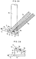
- FIG. 23 A different type of optical device is disclosed in an article titled “Dual-beam CO2 laser cutting of thick metallic materials” (by P. A. Molian) in a technical literature called “Journal of Materials Science” (vol. 28, 1993, P 1738).
- This optical device instead of splitting a single laser beam into a plurality of beams and at the same time converging the split beams with a reflecting mirror provided in close proximity to the workpiece, two laser beams are produced from two laser devices, and these two beams are simply converged on two focal points.
- This optical device is shown in Fig. 23. It has two reflecting mirrors 4, which are simple plane mirrors, and a lens 5 provided between the mirrors 4 and the workpiece W for converging the two laser beams simply on two focal points.
- Unexamined Japanese Patent Publication 5-138385 discloses a method and a device for laser machining which are similar in its structure and object to the optical device disclosed in the abovementioned article. But this device differs in that a plurality of laser beams are converged on a plurality of focal points that are aligned in the direction of thickness of the workpiece W (along the optical axis of the laser beams).
- a lens 5 Fig. 24
- a reflecting mirror Fig 25
- a plurality of laser beams may be converged on focal points that are arranged along a line perpendicular to the axis of the laser beams or along the optical axis.
- a single converging mirror or lens had both the function of splitting a single laser beam into a plurality of beams and the function of converging the split beams on focal points.
- a multifocal optical unit i.e. a lens or a mirror having both of these functions, is very difficult to manufacture because its manufacturing tolerance is extremely narrow, and thus the manufacturing cost is extremely high.
- this optical unit which has to be provided in front of the workpiece, tends to be damaged or polluted by plasmatic particles and debris scattered from the workpiece during machining.
- optical units of this type had to be frequently replaced with new ones because they are easily damaged or polluted. As mentioned above, these optical units are very expensive, so that the maintenance cost of the entire device and thus the machining cost are high.
- An object of this invention is to provide an optical device for laser machining wherein the means for splitting a laser beam is provided separately from the means for converging the split laser beams on predetermined focal points so that the optical unit provided in close proximity to the workpiece can be manufactured with not so high accuracy and thus at low cost, and thus replaced with a new one at low cost.
- an optical device for laser machining comprising a laser oscillator, a transmitter means for transmitting a laser beam produced by the laser oscillator, and a converging means for converging the laser beam received from the transmitter means on a plurality of focal points, the converging means comprising a laser beam splitting unit for splitting the laser beam into a plurality of beams, and a converging unit for converging the split beams on the surface of a workpiece, the laser beam splitting unit being provided separately from and upstream of the converging unit.
- the laser beam splitting unit may be formed from a plurality of splitting members separated from each other by straight lines.
- the laser beam splitting unit may be a reflecting mirror having a plurality of flat reflecting mirror members
- Each flat reflecting mirror member may be arranged so as to be inclinable in a predetermined direction, independently of the other reflecting mirror members.
- the laser beam splitting unit comprising the reflecting mirrors may be supported so as to be movable in a predetermined direction.
- it may be mounted so as to be rotatable about its center.
- the splitting unit may be a splitting window.
- the splitting window may be arranged so as to be movable in a predetermined direction or rotatable about its center, or more preferably both movable in a predetermined direction and also rotatable about its axis.
- the laser beam splitting unit may comprise a plurality of splitting members arranged concentrically around the optical axis of the laser beam.
- Such splitting members may be a combination of concave, convex and plane reflecting mirrors that are arranged concentrically so as to form a reflecting mirror.
- they may be a combination of concave, convex and plane transparent members that are arranged concentrically so as to form a reflecting window.
- the laser beam is split into a plurality of beams in the machining head. It is either split along parallel or radial lines or concentrically.
- the split laser beams converge on focal points arranged on the surface of the workpiece in a plane perpendicular to the optical axis of the laser beams.
- the focal points are arranged along the optical axis.
- the laser beams split by the beam splitting unit in either of the abovementioned two ways are guided to a single-focus converging unit, kept close to each other. Since these beams differ in incident angle and/or diverging angle from one another, they converge on different focal points even though the converging unit itself is a single-focus unit.
- Laser beam splitting units can be manufactured more easily than multifocal converging units. Further, since the splitting unit is provided upstream of the converging unit, it will never be polluted or damaged by molten debris and vapor scattering from the workpiece. Thus, this unit need not be replaced so frequently. This leads to a reduction in the initial setup cost and maintenance cost of the entire optical device.
- the focal points By arranging the focal points on a plane perpendicular to the optical axis, one-dimensional machining of the workpiece is easy. But for actual two- or three-dimensional machining, however, it is necessary, according to the machining direction, to rotate the focal points without changing their relative positions, though this is not necessary if the focal points are arranged along the optical axis.
- the reflecting mirror or window for splitting a laser beam is rotated as shown in Figs. 21A (see fc), 21B. But it was impossible to rotate the focal points by rotating the conventional multifocal converging unit.
- the workpiece By rotating the focal points at a sufficiently high speed, the workpiece can be machined in a "multifocal beam spinning" pattern as shown in Fig. 21C.
- the advantage of this type of machining is that the laser beam energy can be efficiently supplied to the workpiece because the focus of the beams is sufficiently dense even with the same spinning frequency.
- Beam scanning as shown in Fig. 21D is also possible by pivoting the reflecting mirrors or windows (as shown by arrows fd in Fig. 21A) with a galvanometer.
- a converging unit having too short a focal length is not suitable for the machining of a thick plate because its focal depth L is too short, though the laser beams can be focused on sufficiently small spots ⁇ .
- a converging unit having too long a focal distance is also not desirable, because such a unit cannot focus laser beams on sufficiently small spots, though its focal depth L is sufficiently long.
- the focal points are arranged along the optical axis as shown in Fig.
- a reflecting mirror comprising concentrically arranged mirror segments or a window comprising a concentrically arranged transparent members are used.
- Such a mirror or window can be manufactured at low cost.
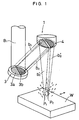
- Fig. 1 is a schematic perspective view of a machining head of the first embodiment. While not shown, the optical device for laser machining of this embodiment has an oscillator for generating a high-energy laser such as a CO2 laser, and a transmitter for transmitting the laser beam produced to the machining head. We omitted them in the drawings because they are well-known in the art.
- a high-energy laser such as a CO2 laser
- An optical element called “window” is provided at a point where the laser beam B transmitted through the transmitter enters the machining head 1, though it is not shown, either. This window serves to prevent molten pieces and vapor produced from the workpiece from entering into the laser beam path, and to seal gas pressure in the machining head.
- the laser beam B1 introduced into the machining head 1 is reflected by a reflecting mirror 3 in an oblique direction.
- the reflecting mirror 3 comprises two semicircular flat mirrors 3a, 3b that are disposed in two different planes intersecting at a predetermined angle so as to split the laser beam B1 into two beams.
- the semicircular mirrors 3a and 3b are mounted so as to be pivotable independently of each other.
- the two beams b1, b2 split and reflected by the reflecting mirror 3 are reflected again by another reflecting mirror 4 which is arranged so that the beams b'1 and b'2 reflected by it are converged on focal points P1 and P2, respectively, on the workpiece W.
- the workpiece is thus machined by the laser beams.
- the reflecting mirror 4 is an ordinary single-focus paraboloidal concave mirror. It is arranged so that the focal points P1 and P2 are located on separate points on the surface of the workpiece W.
- the machining head 1 has a case (not shown) accommodating the window and reflecting mirrors 3 and 4 and provided at its end with a nozzle complementary in shape to the shape of the laser beams b'1, b'2 projected by the mirror 4.
- the workpiece is machined with the laser beams b'1 and b'2 while jetting from the nozzle a high-pressure assist gas (O2 gas for cutting; inert gas (such as N2 and He) for welding) which is introduced from one side of the case.
- a high-pressure assist gas O2 gas for cutting; inert gas (such as N2 and He) for welding
- the reflecting mirror 3 is supported on a base plate 10 through a plurality of piezoelectric elements 11.
- the semicircular mirrors 3a and 3b are pivoted, independently of each other, in the directions of arrows by the piezoelectric elements 11. Namely, by applying a direct current to selected ones of the elements 11, they expand or shrink vertically, so that the semicircular mirrors 3a, 3b are pivoted by small angles.
- the base plate 10 comprises a sliding plate 12 and a fixed plate 13, and has a micrometer 14 at one end thereof.
- the sliding plate 12 slides on the fixed plate 13, so that the reflecting mirror 3 shifts relative to the optical axis of the laser beam B.
- the ratio of reflectance between the beams b'1 and b'2 reflected by the semicircular mirrors 3a and 3b is possible to change the ratio of reflectance between the beams b'1 and b'2 reflected by the semicircular mirrors 3a and 3b.
- the base plate 10 is fixed to the case of the machining head. But preferably, it should be mounted on a rotary plate which can be rotated by any desired angle by a driving means such as a motor. It is possible to change the machining direction or to carry out beam spinning by turning the base plate 10.
- Fig. 2B shows a different means for moving the base plate 10.
- the sliding plate 12 is integrally mounted on a sliding base 12' having a triangular section.
- the base 12' is slidably mounted on the fixed plate 13.
- the laser beam B1 is separated and reflected in two different directions as the two beams b1 and b2. They are then reflected by the reflecting mirror 4 so they will converge on the focal points P1 and P2 on the surface of the workpiece W.
- the semicircular mirrors 3a, 3b are inclined by an angle of e.g. about 0.2 degree relative to each other by applying a high voltage to the piezoelectric elements 11 provided near the borderline between the semicircular mirrors 3a and 3b to expand them.
- the laser beam B1 is directed so that its optical axis will pass precisely the center of the effective reflecting surface of the reflecting mirror 3.
- the two reflected laser beams b1 and b2 have the same energy distribution as shown in Fig. 3B.
- the workpiece W When welding the workpiece W by irradiating it with the laser beams b'1 and b'2 having the same energy distribution (though they may have different distribution), the workpiece W is moved in the direction of arrow in Fig. 1 so as to weld it with the beam converged on the focal point P2 first, and then finish-weld the same area with the beam converged on the focal point P1 for perfect welding.
- the reflecting mirror 4 used in this embodiment is so simple in structure, being in the form of a single paraboloidal concave mirror, that it is inexpensive in comparison with a conventional one having both splitting and converging functions. Thus, the expenses for replacement of such reflecting mirrors are kept to a minimum.
- Figs. 4A and 4B show the machining head of the optical device of the second embodiment and its partial enlarged view.
- This embodiment differs from the first embodiment only in that the laser beam B1 is split into three beams.
- the reflecting mirror 3 is divided into three parts 3a, 3b and 3c along two parallel lines.
- the unillustrated main components (such as the laser oscillator and the beam transmitter) of the optical device and the means for moving and rotating the reflecting mirror 3 are identical in structure to those in the first embodiment.
- the reflecting mirror is divided into three parts along two parallel lines. But it may be divided into four, five or more parts.
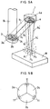
- Figs. 5A and 5B are schematic views of the machining head of the optical device of the third embodiment and its reflecting mirror (plane mirror). It is to be understood that the optical devices of this and the subsequent embodiments up to the sixth embodiments have the main components and adjusting means the same as or similar to those of the first embodiment, unless otherwise stated.
- This embodiment differs from the second embodiment in that the reflecting surface of the reflecting mirror 3 is divided into three equal sectors 3a, 3b and 3c along three radial lines (Fig. 5B).
- focal points P1, P2 and P3 are arranged along a straight line in the second embodiment, they are arranged at the vertexes of a triangle in the third embodiment.
- the positions of the focal points P1, P2 and P3 are adjustable relative to one another. Since the three focal points P1, P2 and P3 are arranged to form a triangle, the optical device of this embodiment is especially suited for such machining work as boring, spinning and beam scanning.
- Figs. 6A, 6B schematically show the machining head of the optical device of the fourth embodiment.
- the reflecting surface of the reflecting mirror 3 is divided into a plurality of equal sectors having the same central angles. Namely, in this embodiment, the surface of the reflecting mirror 3 is divided into four equal sectors 3a, 3b, 3c and 3d along four radial lines so as to split the laser beam B1 into four laser beams b1, b2, b3 and b4.
- the laser beam is split into four equal beams.
- the reflecting mirror 3 up or down (C, D), or right or left (B, A), the above ratio can be changed freely.
- Fig. 7 schematically shows the machining head of the optical device of the fifth embodiment in which the reflecting mirror 3 is an ordinary plane mirror.
- the laser beam B1 is reflected by the mirror 3, and the beam B2 thus reflected is split into a plurality of (three in this embodiment) beams by another reflecting mirror 4 in the same way as with the reflecting mirrors 3 in the first to fourth embodiments.
- the reflecting mirror 4 has its reflecting surface divided into three segments 4a, 4b, and 4c along two parallel lines. These segments have only the function of splitting and reflecting the laser beam.
- the reflecting mirror 4 has its back supported on a base plate 10 through a means 11 for adjusting the inclination of the segments 4a, 4b and 4c.
- the split laser beams b1, b2 and b3 pass through a condensing or converging lens 5 and converged on focal points P1, P2 and P3 on the surface of the workpiece W.
- the function of splitting the laser beam and the function of converging the split beams are provided separately from each other. Namely, the laser beam is first split into a plurality of beams by the reflecting mirror 4, and then passes through the condensing lens 5.
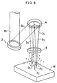
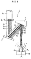
- Fig. 8 schematically shows the machining head of the sixth embodiment, which is a modified embodiment of the fifth embodiment shown in Fig. 7 and differs therefrom in the way in which the laser beam B2 is split into three laser beams b1, b2 and b3 by the reflecting mirror 4.
- the reflecting mirror 4 in this embodiment split the laser beam along radial lines extending radially from the center of the reflecting mirror 4.
- the split beams are converged on focal points P1, P2 and P3 that are disposed at the vertexes of a triangle.
- the split laser beams b1, b2 and b2 reflected by the reflecting mirror 4 are converged on the focal points P1, P2 and P3 by the same condensing lens 5 used in the embodiment of Fig. 7.
- Fig. 9 is a schematic sectional view of the machining head of the seventh embodiment.
- the laser beam B1 is split into a plurality of (three in the embodiment) beams by a window 2 provided at the laser beam inlet of the machining head, reflected by a single flat reflecting mirror 3, and reflected by another reflecting mirror 4 having a single paraboloidal surface so as to be converged on focal points P1, P2 and P3 on the surface of the workpiece W.
- the window 2 has the function of splitting the laser beam, while the reflecting mirror 3 is a single, flat reflecting mirror.
- the single paraboloidal reflecting mirror 4 has only the function of reflecting and converging the split beams.
- the window 2 is provided farthest from the workpiece W, so that there is little possibility that the window 2 be polluted or damaged by any debris or dust scattered from the workpiece W during machining.
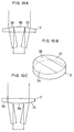
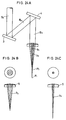
- Figs. 10A, 10A' and 10B show, in section and in perspective, the shape of the window 2 of this embodiment.
- the window 2 is divided into an inclined surface 2A, a horizontal surface 2B and an inclined surface 2C along two parallel, straight lines.
- Fig. 10A' clearly shows how they are arranged. As shown in Fig. 10C, these surfaces may be formed on the opposite side of the window.
- This window 2 of this embodiment may be mounted so as to be movable in a predetermined direction and rotatable about its center as in the first embodiment.
- the window 2 may be supported on a holder (not shown) moved by a micrometer similar to the micrometer in the first embodiment.
- the holder may be rotated with a motor which can rotate the holder by a very small angle, such as a stepping motor.
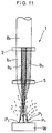
- Fig. 11 is a schematic sectional view of the machining head of the eighth embodiment. As shown, no reflecting mirror is used in this embodiment. Instead, the laser beam B1 is split into a plurality of beams b1, b2 and b3 by a window 2 which is not a plane light-passing window but a window having three sections that pass light in different directions. The split beams are converged on focal points P1, P2 and P3 by a condensing lens 5. Namely, the condensing lens has no function of splitting the laser beam.
- the function of splitting the laser beam and the function of converting the split beams on focal points are provided separately from each other.
- the window 2, provided farther from the workpiece, is far less likely to be polluted or damaged than the condensing lens 5.
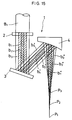
- Fig. 12 is a schematic sectional view of the machining head of the ninth embodiment.
- the split laser beams are converged on a plurality of focal points that are arranged laterally on the surface of the workpiece, i.e. along a line that is perpendicular to the optical axis of the beams.
- the laser beam is split and converged on a plurality of focal points that are arranged axially along the optical axis of the beams.
- the laser beam B1 is reflected by a reflecting mirror 3.
- the reflecting mirror 3 comprises concentric segments 3A, 3B and 3C.
- the innermost segment 3A, the intermediate one 3B and the outermost one 3C may have a convex surface, a flat surface, and a concave surface, respectively (Fig. 13A).
- These mirror segments are integral with each other.
- the laser beam is reflected and split by the reflecting mirror 3 into laser beams b1, b2 and b3, which are reflected again by another reflecting mirror 4.
- the thus reflected beams b'1, b'2 and b'3 converge on focal points P1, P2 and P3, respectively.
- the function of splitting the laser beam and the function of converting the split beams on focal points are provided separately from each other.
- the reflecting mirror 3, provided farther from the workpiece, is far less likely to be polluted or damaged than the reflecting mirror 4.
- Fig. 14A is a schematic sectional view of the machining head of the tenth embodiment and Figs. 14B-14D are its partial exploded views.
- two flat or substantially flat reflecting mirrors 3 and 4 are used. No paraboloidal reflecting mirror is used.
- the reflecting mirror 4 has, like the reflecting mirror of the ninth embodiment (Fig. 12), an innermost convex surface, a middle flat surface, and an outermost concave surface. The diameters of the laser beams reflected from the convex and concave surfaces increase and decrease only slightly.
- the split laser beams b1, b2 and b3 reflected from the reflecting mirror 4 are converged on focal points P1, P2 and P3, respectively, by the condensing lens 5.
- the focal points P1, P2 and P3 are arranged along the center axis of the beams.
- the laser beams b1, b2 and b3 appear to be parallel beams. But actually, the beam b1 is expanding slightly toward the lens 5, while the beam b3 is shrinking slightly toward the lens 5.
- Fig. 15 is a schematic sectional view of the machining head of the 11th embodiment. It includes a window 2, a flat reflecting mirror 3, and a paraboloidal reflecting mirror 4.
- the window 2 is not a simple flat-surfaced window but a transparent window having an innermost concave surface 2A, a middle flat surface 2B, and an outermost convex surface 2C (Fig. 16).
- the reflecting mirror 3 is a single flat mirror.
- the reflecting mirror 4 is a single paraboloidal reflecting mirror.
- the surfaces 2A, 2B and 2C may be formed on the side of the window 2 facing the laser beam B1, or on the other side thereof.
- the split laser beams b1, b2 and b3 are reflected by the reflecting mirror 3.
- the thus reflected beams b'1, b'2 and b'3 are reflected by the reflecting mirror 4, so that the thus reflected beams b''1, b''2 and b''3 converge on focal points P1, P2 and P3.
- Fig. 17 shows a schematic sectional view of the machining head of the 12th embodiment.
- the reflecting mirrors 3 and 4 used in the 11th embodiment are omitted.
- the laser beam B1 is split by a window 2 and converged on a plurality of focal points by a condensing lens 5.
- the window 2 is of exactly the same type used in the 11th embodiment, while the condensing lens 5 is exactly the same type used in the tenth embodiment.
- the laser beam B1 is split into three beams b1, b2 and b3 by the window 2.
- the split beams b1, b2 and b3 are then converged on focal points P1, P2 and P3 by the condensing lens 5.
Abstract
Description
- This invention relates to an optical device for laser machining, more specifically an optical device having a multifocal converging optical system having the function of converging a single laser beam on a plurality of focal points.
- Lasers such as CO₂ lasers and YAG lasers are used for cutting, welding and boring a workpiece by using a high-energy laser beam produced from their oscillator. An optical device used for such laser machining has a laser oscillator for producing a laser beam, a transmitter for guiding the laser beam produced by the oscillator into a machining head, and a converging optical unit provided in the machining head for converging and condensing the laser beam to a high energy density to irradiate a target area of the workpiece.
- For such laser machining as cutting, welding and boring, a single, high-energy laser beam produced by the oscillator is ordinarily converged on a workpiece as it is. But now, many trials are being made to split a single laser beam into two or more beams and irradiate a workpiece with a plurality of split beams for versatility in machining.
- For example, Unexamined Japanese Patent Publication 62-254991, "METHOD AND DEVICE FOR LASER WELDING", proposes to split a single laser beam into two beams. An object of this reference is to provide a method for laser welding which can deepen the weld penetration (keyhole). With this method, it is possible to increase the weld speed with small heat input, less thermal strain, and thus to protect the surrounding area from thermal effect.
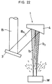
- The optical device used to carry out the method disclosed in this publication is shown in Fig. 22. It is a twin-spot laser welding machine comprising a laser oscillator (CO₂ laser) for producing a laser beam, a reflecting
mirror 3 for reflecting the laser beam, and another reflectingmirror 4 for reflecting the laser beam again and at the same time splitting the laser beam into two beams so that these two beams will converge on two focal points laterally spaced from each other on the surface of the workpiece W. - A converging device for laser machining having the same object as that of the above reference is disclosed in Unexamined Japanese Patent Publication 4-182087. This device is structurally similar to the abovementioned device. Namely, this device has a bifocal mirror for converging a laser beam on two focal points laterally spaced from each other on the surface of the workpiece.
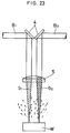
- A different type of optical device is disclosed in an article titled "Dual-beam CO₂ laser cutting of thick metallic materials" (by P. A. Molian) in a technical literature called "Journal of Materials Science" (vol. 28, 1993, P 1738). In the arrangement disclosed in this article, instead of splitting a single laser beam into a plurality of beams and at the same time converging the split beams with a reflecting mirror provided in close proximity to the workpiece, two laser beams are produced from two laser devices, and these two beams are simply converged on two focal points. This optical device is shown in Fig. 23. It has two reflecting
mirrors 4, which are simple plane mirrors, and alens 5 provided between themirrors 4 and the workpiece W for converging the two laser beams simply on two focal points. - It is stated in this article that a thick metallic material can be cut effectively by using two laser beams instead of one. But in this reference, in order to produce such two laser beams, two independent laser devices have to be used.
- Unexamined Japanese Patent Publication 5-138385 discloses a method and a device for laser machining which are similar in its structure and object to the optical device disclosed in the abovementioned article. But this device differs in that a plurality of laser beams are converged on a plurality of focal points that are aligned in the direction of thickness of the workpiece W (along the optical axis of the laser beams). For this purpose, a lens 5 (Fig. 24) or a reflecting mirror (Fig 25) is provided near the workpiece W.
- As will be apparent from the above discussion, the technique of converging two or more high-energy laser beams on respective focal points is now widely accepted as an effective way to form a deep cut or weld penetration in a workpiece.
- A plurality of laser beams may be converged on focal points that are arranged along a line perpendicular to the axis of the laser beams or along the optical axis.
- Heretofore, a single converging mirror or lens had both the function of splitting a single laser beam into a plurality of beams and the function of converging the split beams on focal points. Such a multifocal optical unit, i.e. a lens or a mirror having both of these functions, is very difficult to manufacture because its manufacturing tolerance is extremely narrow, and thus the manufacturing cost is extremely high.
- Another problem is that this optical unit, which has to be provided in front of the workpiece, tends to be damaged or polluted by plasmatic particles and debris scattered from the workpiece during machining.
- In order to prolong the life of the optical unit, various measures were taken to protect it from such particles and debris. But none of them were satisfactory. Namely, optical units of this type had to be frequently replaced with new ones because they are easily damaged or polluted. As mentioned above, these optical units are very expensive, so that the maintenance cost of the entire device and thus the machining cost are high.
- An object of this invention is to provide an optical device for laser machining wherein the means for splitting a laser beam is provided separately from the means for converging the split laser beams on predetermined focal points so that the optical unit provided in close proximity to the workpiece can be manufactured with not so high accuracy and thus at low cost, and thus replaced with a new one at low cost.
- According to this invention, there is provided an optical device for laser machining comprising a laser oscillator, a transmitter means for transmitting a laser beam produced by the laser oscillator, and a converging means for converging the laser beam received from the transmitter means on a plurality of focal points, the converging means comprising a laser beam splitting unit for splitting the laser beam into a plurality of beams, and a converging unit for converging the split beams on the surface of a workpiece, the laser beam splitting unit being provided separately from and upstream of the converging unit.
- In order to converge the split laser beams on focal points that are arranged on the surface of the workpiece in a plane perpendicular to the optical axis, the laser beam splitting unit may be formed from a plurality of splitting members separated from each other by straight lines.
- The laser beam splitting unit may be a reflecting mirror having a plurality of flat reflecting mirror members
- Each flat reflecting mirror member may be arranged so as to be inclinable in a predetermined direction, independently of the other reflecting mirror members.
- Also, the laser beam splitting unit comprising the reflecting mirrors may be supported so as to be movable in a predetermined direction.
- Further, it may be mounted so as to be rotatable about its center.
- As another means for converging the split laser beams on focal points arranged in a plane perpendicular to the optical axis, the splitting unit may be a splitting window.
- The splitting window may be arranged so as to be movable in a predetermined direction or rotatable about its center, or more preferably both movable in a predetermined direction and also rotatable about its axis.
- In order to arrange the focal points along the optical axis, the laser beam splitting unit may comprise a plurality of splitting members arranged concentrically around the optical axis of the laser beam.
- Such splitting members may be a combination of concave, convex and plane reflecting mirrors that are arranged concentrically so as to form a reflecting mirror.
- Otherwise, they may be a combination of concave, convex and plane transparent members that are arranged concentrically so as to form a reflecting window.
- According to the present invention, the laser beam is split into a plurality of beams in the machining head. It is either split along parallel or radial lines or concentrically. In the former case, the split laser beams converge on focal points arranged on the surface of the workpiece in a plane perpendicular to the optical axis of the laser beams. In the latter case, the focal points are arranged along the optical axis. By converging split laser beams on a plurality of focal points, the energy density can be distributed differently from when converging a single laser beam on a single focal point. Thus, it is possible to use this technique in a variety of laser machining applications.
- The laser beams split by the beam splitting unit in either of the abovementioned two ways are guided to a single-focus converging unit, kept close to each other. Since these beams differ in incident angle and/or diverging angle from one another, they converge on different focal points even though the converging unit itself is a single-focus unit.
- Laser beam splitting units can be manufactured more easily than multifocal converging units. Further, since the splitting unit is provided upstream of the converging unit, it will never be polluted or damaged by molten debris and vapor scattering from the workpiece. Thus, this unit need not be replaced so frequently. This leads to a reduction in the initial setup cost and maintenance cost of the entire optical device.
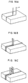
- Let us now describe in more detail various advantages of converging laser beams on a plurality of focal points. First, we will describe the arrangement in which laser beams are converged on focal points arranged in a plane perpendicular to the optical axis. By converging two laser beams on two focal points as shown in Fig. 18A, it is possible to cut or weld the workpiece with the first beam and then cut or weld it further deeply with the second beam (keyhole effect). By converging beams as shown in Fig. 18B, it is possible to eliminate the necessity of butting two workpieces together with high accuracy when butt-welding them. By converging four beams on four focal points as shown in Fig. 18C, both the above effects are achievable. Also, as shown in Figs. 19A, 19B, laser beams may be converged on a plurality of focal points to form a plurality of patterns of the same shape.
- By arranging the focal points on a plane perpendicular to the optical axis, one-dimensional machining of the workpiece is easy. But for actual two- or three-dimensional machining, however, it is necessary, according to the machining direction, to rotate the focal points without changing their relative positions, though this is not necessary if the focal points are arranged along the optical axis. In this case, according to the present invention, the reflecting mirror or window for splitting a laser beam is rotated as shown in Figs. 21A (see fc), 21B. But it was impossible to rotate the focal points by rotating the conventional multifocal converging unit.
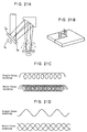
- By rotating the focal points at a sufficiently high speed, the workpiece can be machined in a "multifocal beam spinning" pattern as shown in Fig. 21C. The advantage of this type of machining is that the laser beam energy can be efficiently supplied to the workpiece because the focus of the beams is sufficiently dense even with the same spinning frequency.
- Beam scanning as shown in Fig. 21D is also possible by pivoting the reflecting mirrors or windows (as shown by arrows fd in Fig. 21A) with a galvanometer.
- One advantage of arranging the focal points along the optical axis is, as explained in Unexamined Japanese Patent Publication 5-138385, that a thick plate can be machined efficiently. As shown in Fig. 20A, a converging unit having too short a focal length is not suitable for the machining of a thick plate because its focal depth L is too short, though the laser beams can be focused on sufficiently small spots φ. However, as shown in Fig. 20B, a converging unit having too long a focal distance is also not desirable, because such a unit cannot focus laser beams on sufficiently small spots, though its focal depth L is sufficiently long. Thus, according to this invention, the focal points are arranged along the optical axis as shown in Fig. 20C so that laser beams are focused on sufficiently small spots φ, while keeping a sufficiently long focal depth L'. With this arrangement, it is possible to machine a rather thick plate member and also to machine a workpiece even if its positioning accuracy is not very high (e.g. even if the workpiece moves in the direction of the optical axis). Namely, with this arrangement, it is possible to machine the workpiece properly even if the focal points move relative to the workpiece.
- In order to arrange the focal points along the optical axis of the laser beam, a reflecting mirror comprising concentrically arranged mirror segments or a window comprising a concentrically arranged transparent members are used. Such a mirror or window can be manufactured at low cost.
- Other features and objects of the present invention will become apparent from the following description made with reference to the accompanying drawings, in which:
- Fig. 1 is a schematic perspective view of a machining head of an optical device of a first embodiment;
- Figs. 2A and 2B are detailed views of the same;
- Figs. 3A and 3B are views explaining its operation;
- Fig. 4A is a schematic perspective view of a second embodiment;
- Fig. 4B is its detailed sectional view;
- Figs. 5A and 5B are similar views of a third embodiment;
- Figs. 6A and 6B are similar views of a fourth embodiment;
- Fig. 7 is a schematic perspective view of a fifth embodiment;
- Fig. 8 is a schematic perspective view of a sixth embodiment;
- Fig. 9 is a schematic perspective view of a seventh embodiment;
- Figs. 10A-10C are detailed views of a window of the machining head of the seventh embodiment;
- Fig. 11 is a schematic perspective view of an eighth embodiment;
- Fig. 12 is a schematic sectional view of a ninth embodiment;
- Fig. 13A and 13B are views for explaining its operation of the same;
- Fig. 14A is a schematic sectional view of a tenth embodiment;
- Figs. 14B, 14C and 14D are partial detailed views of the same;
- Fig. 15 is a schematic sectional view of an 11th embodiment;
- Figs. 16A-16C are partial enlarged sectional views of the same;
- Fig. 17 is a partial enlarged sectional view of a 12th embodiment;
- Figs. 18-21 are explaining the principle of laser machining; and
- Figs. 22-25 are schematic sectional view of a machining head of conventional optical devices.
- Embodiments of this invention are described with refere to the drawings.
- Fig. 1 is a schematic perspective view of a machining head of the first embodiment. While not shown, the optical device for laser machining of this embodiment has an oscillator for generating a high-energy laser such as a CO₂ laser, and a transmitter for transmitting the laser beam produced to the machining head. We omitted them in the drawings because they are well-known in the art.
- An optical element called "window" is provided at a point where the laser beam B transmitted through the transmitter enters the
machining head 1, though it is not shown, either. This window serves to prevent molten pieces and vapor produced from the workpiece from entering into the laser beam path, and to seal gas pressure in the machining head. - The laser beam B1 introduced into the
machining head 1 is reflected by a reflectingmirror 3 in an oblique direction. It is a multisegment reflecting mirror for reflecting the laser beams B1 into two beams. Namely, the reflectingmirror 3 comprises two semicircularflat mirrors semicircular mirrors - The two beams b1, b2 split and reflected by the reflecting
mirror 3 are reflected again by another reflectingmirror 4 which is arranged so that the beams b'1 and b'2 reflected by it are converged on focal points P1 and P2, respectively, on the workpiece W. The workpiece is thus machined by the laser beams. The reflectingmirror 4 is an ordinary single-focus paraboloidal concave mirror. It is arranged so that the focal points P1 and P2 are located on separate points on the surface of the workpiece W. - The
machining head 1 has a case (not shown) accommodating the window and reflectingmirrors mirror 4. The workpiece is machined with the laser beams b'1 and b'2 while jetting from the nozzle a high-pressure assist gas (O₂ gas for cutting; inert gas (such as N₂ and He) for welding) which is introduced from one side of the case. - Referring to the enlarged sectional view of Fig. 2A, the reflecting
mirror 3 is supported on abase plate 10 through a plurality ofpiezoelectric elements 11. Thesemicircular mirrors piezoelectric elements 11. Namely, by applying a direct current to selected ones of theelements 11, they expand or shrink vertically, so that thesemicircular mirrors - The
base plate 10 comprises a slidingplate 12 and a fixedplate 13, and has amicrometer 14 at one end thereof. By activating themicrometer 14, the slidingplate 12 slides on the fixedplate 13, so that the reflectingmirror 3 shifts relative to the optical axis of the laser beam B. Thus, it is possible to change the ratio of reflectance between the beams b'1 and b'2 reflected by thesemicircular mirrors - In this embodiment, the
base plate 10 is fixed to the case of the machining head. But preferably, it should be mounted on a rotary plate which can be rotated by any desired angle by a driving means such as a motor. It is possible to change the machining direction or to carry out beam spinning by turning thebase plate 10. - Fig. 2B shows a different means for moving the
base plate 10. In this example, the slidingplate 12 is integrally mounted on a sliding base 12' having a triangular section. The base 12' is slidably mounted on the fixedplate 13. - Now the operation of the first embodiment is described.
- In the
machining head 1, the laser beam B1 is separated and reflected in two different directions as the two beams b1 and b2. They are then reflected by the reflectingmirror 4 so they will converge on the focal points P1 and P2 on the surface of the workpiece W. - In order to split the laser beam B1 into two beams with the reflecting
mirror 3, as shown in Fig. 3A, thesemicircular mirrors piezoelectric elements 11 provided near the borderline between thesemicircular mirrors - In the embodiment shown, the laser beam B1 is directed so that its optical axis will pass precisely the center of the effective reflecting surface of the reflecting
mirror 3. Thus, the two reflected laser beams b1 and b2 have the same energy distribution as shown in Fig. 3B. - When welding the workpiece W by irradiating it with the laser beams b'1 and b'2 having the same energy distribution (though they may have different distribution), the workpiece W is moved in the direction of arrow in Fig. 1 so as to weld it with the beam converged on the focal point P2 first, and then finish-weld the same area with the beam converged on the focal point P1 for perfect welding.
- During welding, dust, molten debris and vapor coming from the workpiece W will be scattered in the machining head, so that the reflecting
mirror 4, provided in close proximity to the workpiece W, will be damaged or polluted to such an extent that it has to be replaced with a new one. But the reflectingmirror 4 used in this embodiment is so simple in structure, being in the form of a single paraboloidal concave mirror, that it is inexpensive in comparison with a conventional one having both splitting and converging functions. Thus, the expenses for replacement of such reflecting mirrors are kept to a minimum. - Heretofore, a laser beam was split and converged using reflecting mirrors whose reflecting surfaces were immovable. Thus, it was impossible to the change the beam splitting ratio and the converging points, or to rotate the converging points. With the arrangement of the embodiment, all of the above three adjustments are possible.
- Figs. 4A and 4B show the machining head of the optical device of the second embodiment and its partial enlarged view. This embodiment differs from the first embodiment only in that the laser beam B1 is split into three beams. For this purpose, the reflecting
mirror 3 is divided into threeparts - The unillustrated main components (such as the laser oscillator and the beam transmitter) of the optical device and the means for moving and rotating the reflecting
mirror 3 are identical in structure to those in the first embodiment. - In this embodiment, the reflecting mirror is divided into three parts along two parallel lines. But it may be divided into four, five or more parts.
- Figs. 5A and 5B are schematic views of the machining head of the optical device of the third embodiment and its reflecting mirror (plane mirror). It is to be understood that the optical devices of this and the subsequent embodiments up to the sixth embodiments have the main components and adjusting means the same as or similar to those of the first embodiment, unless otherwise stated. This embodiment differs from the second embodiment in that the reflecting surface of the reflecting
mirror 3 is divided into threeequal sectors - Thus, while the focal points P1, P2 and P3 are arranged along a straight line in the second embodiment, they are arranged at the vertexes of a triangle in the third embodiment. The positions of the focal points P1, P2 and P3 are adjustable relative to one another. Since the three focal points P1, P2 and P3 are arranged to form a triangle, the optical device of this embodiment is especially suited for such machining work as boring, spinning and beam scanning.
- Figs. 6A, 6B schematically show the machining head of the optical device of the fourth embodiment. In this embodiment, similar to the embodiment of Fig. 5, the reflecting surface of the reflecting
mirror 3 is divided into a plurality of equal sectors having the same central angles. Namely, in this embodiment, the surface of the reflectingmirror 3 is divided into fourequal sectors - Referring to Fig. 6B, if the reflecting
mirror 3 is positioned so that the optical axis of the laser beam B2 passes the center of the reflecting mirror, the laser beam is split into four equal beams. By moving the reflectingmirror 3 up or down (C, D), or right or left (B, A), the above ratio can be changed freely. - In the other embodiments, too, it is possible to change this rate by moving the reflecting
mirror 3. - It is of course possible to divide the reflecting mirror into more than four segments along radial lines.
- Fig. 7 schematically shows the machining head of the optical device of the fifth embodiment in which the reflecting
mirror 3 is an ordinary plane mirror. The laser beam B1 is reflected by themirror 3, and the beam B2 thus reflected is split into a plurality of (three in this embodiment) beams by another reflectingmirror 4 in the same way as with the reflectingmirrors 3 in the first to fourth embodiments. - As in the second embodiment, the reflecting
mirror 4 has its reflecting surface divided into threesegments mirror 4 has its back supported on abase plate 10 through ameans 11 for adjusting the inclination of thesegments - The split laser beams b1, b2 and b3 pass through a condensing or converging
lens 5 and converged on focal points P1, P2 and P3 on the surface of the workpiece W. - In this embodiment, similar to the first to fourth embodiments, the function of splitting the laser beam and the function of converging the split beams are provided separately from each other. Namely, the laser beam is first split into a plurality of beams by the reflecting
mirror 4, and then passes through the condensinglens 5. - Fig. 8 schematically shows the machining head of the sixth embodiment, which is a modified embodiment of the fifth embodiment shown in Fig. 7 and differs therefrom in the way in which the laser beam B2 is split into three laser beams b1, b2 and b3 by the reflecting
mirror 4. Namely, the reflectingmirror 4 in this embodiment split the laser beam along radial lines extending radially from the center of the reflectingmirror 4. Thus, the split beams are converged on focal points P1, P2 and P3 that are disposed at the vertexes of a triangle. - The split laser beams b1, b2 and b2 reflected by the reflecting
mirror 4 are converged on the focal points P1, P2 and P3 by thesame condensing lens 5 used in the embodiment of Fig. 7. - Fig. 9 is a schematic sectional view of the machining head of the seventh embodiment. In this embodiment, the laser beam B1 is split into a plurality of (three in the embodiment) beams by a
window 2 provided at the laser beam inlet of the machining head, reflected by a single flat reflectingmirror 3, and reflected by another reflectingmirror 4 having a single paraboloidal surface so as to be converged on focal points P1, P2 and P3 on the surface of the workpiece W. - In this embodiment, the
window 2 has the function of splitting the laser beam, while the reflectingmirror 3 is a single, flat reflecting mirror. The singleparaboloidal reflecting mirror 4 has only the function of reflecting and converging the split beams. Of these three members, thewindow 2 is provided farthest from the workpiece W, so that there is little possibility that thewindow 2 be polluted or damaged by any debris or dust scattered from the workpiece W during machining. - Figs. 10A, 10A' and 10B show, in section and in perspective, the shape of the
window 2 of this embodiment. First, referring to Fig. 10A, thewindow 2 is divided into aninclined surface 2A, ahorizontal surface 2B and aninclined surface 2C along two parallel, straight lines. Fig. 10A' clearly shows how they are arranged. As shown in Fig. 10C, these surfaces may be formed on the opposite side of the window. - This
window 2 of this embodiment may be mounted so as to be movable in a predetermined direction and rotatable about its center as in the first embodiment. In this case, thewindow 2 may be supported on a holder (not shown) moved by a micrometer similar to the micrometer in the first embodiment. Also, the holder may be rotated with a motor which can rotate the holder by a very small angle, such as a stepping motor. - Fig. 11 is a schematic sectional view of the machining head of the eighth embodiment. As shown, no reflecting mirror is used in this embodiment. Instead, the laser beam B1 is split into a plurality of beams b1, b2 and b3 by a
window 2 which is not a plane light-passing window but a window having three sections that pass light in different directions. The split beams are converged on focal points P1, P2 and P3 by a condensinglens 5. Namely, the condensing lens has no function of splitting the laser beam. - As will be apparent from the above description, in this embodiment, like the other embodiments, the function of splitting the laser beam and the function of converting the split beams on focal points are provided separately from each other. Thus, the
window 2, provided farther from the workpiece, is far less likely to be polluted or damaged than the condensinglens 5. - Fig. 12 is a schematic sectional view of the machining head of the ninth embodiment. In the first through eighth embodiments, the split laser beams are converged on a plurality of focal points that are arranged laterally on the surface of the workpiece, i.e. along a line that is perpendicular to the optical axis of the beams. In sharp contrast, in this embodiment, the laser beam is split and converged on a plurality of focal points that are arranged axially along the optical axis of the beams.
- The laser beam B1 is reflected by a reflecting
mirror 3. As shown in the sectional view taken along line A-A of Fig. 12, and Figs. 13A and 13B, the reflectingmirror 3 comprisesconcentric segments innermost segment 3A, the intermediate one 3B and the outermost one 3C may have a convex surface, a flat surface, and a concave surface, respectively (Fig. 13A). These mirror segments are integral with each other. - The laser beam is reflected and split by the reflecting
mirror 3 into laser beams b1, b2 and b3, which are reflected again by another reflectingmirror 4. The thus reflected beams b'1, b'2 and b'3 converge on focal points P1, P2 and P3, respectively. - Thus, in this embodiment, like the other embodiments, the function of splitting the laser beam and the function of converting the split beams on focal points are provided separately from each other. The reflecting
mirror 3, provided farther from the workpiece, is far less likely to be polluted or damaged than the reflectingmirror 4. - The diameters of the laser beams b1 and b3, which reflect from the convex and concave surfaces of the reflecting
mirror 3, slightly increase and decrease as they go away from themirror 3. In Fig. 13A, such increase and decrease in diameters are shown in a rather exaggerated manner. - Fig. 14A is a schematic sectional view of the machining head of the tenth embodiment and Figs. 14B-14D are its partial exploded views. In this embodiment, two flat or substantially flat reflecting
mirrors mirror 4 has, like the reflecting mirror of the ninth embodiment (Fig. 12), an innermost convex surface, a middle flat surface, and an outermost concave surface. The diameters of the laser beams reflected from the convex and concave surfaces increase and decrease only slightly. - The split laser beams b1, b2 and b3 reflected from the reflecting
mirror 4 are converged on focal points P1, P2 and P3, respectively, by the condensinglens 5. The focal points P1, P2 and P3 are arranged along the center axis of the beams. In Fig. 14A, the laser beams b1, b2 and b3 appear to be parallel beams. But actually, the beam b1 is expanding slightly toward thelens 5, while the beam b3 is shrinking slightly toward thelens 5. - Fig. 15 is a schematic sectional view of the machining head of the 11th embodiment. It includes a
window 2, a flat reflectingmirror 3, and aparaboloidal reflecting mirror 4. Thewindow 2 is not a simple flat-surfaced window but a transparent window having an innermostconcave surface 2A, a middleflat surface 2B, and an outermostconvex surface 2C (Fig. 16). The reflectingmirror 3 is a single flat mirror. The reflectingmirror 4 is a single paraboloidal reflecting mirror. - As shown in Figs. 16A and 16B, the
surfaces window 2 facing the laser beam B1, or on the other side thereof. - The split laser beams b1, b2 and b3 are reflected by the reflecting
mirror 3. The thus reflected beams b'1, b'2 and b'3 are reflected by the reflectingmirror 4, so that the thus reflected beams b''1, b''2 and b''3 converge on focal points P1, P2 and P3. - Fig. 17 shows a schematic sectional view of the machining head of the 12th embodiment. In this embodiment, the reflecting
mirrors window 2 and converged on a plurality of focal points by a condensinglens 5. - The
window 2 is of exactly the same type used in the 11th embodiment, while the condensinglens 5 is exactly the same type used in the tenth embodiment. - In this embodiment, the laser beam B1 is split into three beams b1, b2 and b3 by the
window 2. The split beams b1, b2 and b3 are then converged on focal points P1, P2 and P3 by the condensinglens 5.
Claims (12)
- An optical device for laser machining comprising a laser oscillator, a transmitter means for transmitting a laser beam produced by said laser oscillator, and a converging means for converging said laser beam received from said transmitter means on a plurality of focal points, said converging means comprising a laser beam splitting unit for splitting said laser beam into a plurality of beams, and a converging unit for converging said split beams on the surface of a workpiece, said laser beam splitting unit being provided separately from and upstream of said converging unit.
- An optical device for laser machining as claimed in claim 1 wherein said laser beam splitting unit comprises a plurality of splitting members separated from each other by straight lines.
- An optical device for laser machining as claimed in claim 2 wherein said laser beam splitting unit is a reflecting mirror having a plurality of flat reflecting mirror members.
- An optical device for laser machining as claimed in claim 3 wherein said each flat reflecting mirror member can be inclined in a predetermined direction, independently of any other reflecting mirrors.
- An optical device for laser machining as claimed in claim 3 or 4 wherein said reflecting mirror is movable in a predetermined direction.
- An optical device for laser machining as claimed in any of claims 3-5 wherein said reflecting mirror is rotatable about its center.
- An optical device for laser machining as claimed in claim 2 wherein said laser beam splitting unit is a splitting window.
- An optical device for laser machining as claimed in claim 7 wherein said splitting window is movable in a predetermined direction.
- An optical device for laser machining as claimed in claim 7 or 8 wherein said splitting window is rotatable about its center.
- An optical device for laser machining as claimed in claim 1 wherein said laser beam splitting unit comprises a plurality of splitting members arranged concentrically around the optical axis of the laser beam.
- An optical device for laser machining as claimed in claim 10 wherein said splitting members are a combination of concave, convex and plane reflecting mirrors arranged concentrically so as to form a reflecting mirror.
- An optical device for laser machining as claimed in claim 10 wherein said splitting members are a combination of concave, convex and plane transparent members arranged concentrically so as to form a window.
Priority Applications (1)
| Application Number | Priority Date | Filing Date | Title |
|---|---|---|---|
| EP98114951A EP0882540B1 (en) | 1994-10-07 | 1995-10-02 | Optical device for laser machining |
Applications Claiming Priority (3)
| Application Number | Priority Date | Filing Date | Title |
|---|---|---|---|
| JP6243913A JPH08108289A (en) | 1994-10-07 | 1994-10-07 | Optical device for laser beam machining |
| JP24391394 | 1994-10-07 | ||
| JP243913/94 | 1994-10-07 |
Related Child Applications (1)
| Application Number | Title | Priority Date | Filing Date |
|---|---|---|---|
| EP98114951A Division EP0882540B1 (en) | 1994-10-07 | 1995-10-02 | Optical device for laser machining |
Publications (3)
| Publication Number | Publication Date |
|---|---|
| EP0706072A2 true EP0706072A2 (en) | 1996-04-10 |
| EP0706072A3 EP0706072A3 (en) | 1996-12-11 |
| EP0706072B1 EP0706072B1 (en) | 2001-09-05 |
Family
ID=17110877
Family Applications (2)
| Application Number | Title | Priority Date | Filing Date |
|---|---|---|---|
| EP95115540A Expired - Lifetime EP0706072B1 (en) | 1994-10-07 | 1995-10-02 | Optical device for laser machining |
| EP98114951A Expired - Lifetime EP0882540B1 (en) | 1994-10-07 | 1995-10-02 | Optical device for laser machining |
Family Applications After (1)
| Application Number | Title | Priority Date | Filing Date |
|---|---|---|---|
| EP98114951A Expired - Lifetime EP0882540B1 (en) | 1994-10-07 | 1995-10-02 | Optical device for laser machining |
Country Status (6)
| Country | Link |
|---|---|
| US (1) | US5690845A (en) |
| EP (2) | EP0706072B1 (en) |
| JP (1) | JPH08108289A (en) |
| KR (1) | KR100234491B1 (en) |
| CA (1) | CA2159887A1 (en) |
| DE (2) | DE69522522T2 (en) |
Cited By (26)
| Publication number | Priority date | Publication date | Assignee | Title |
|---|---|---|---|---|
| FR2746047A1 (en) * | 1996-03-13 | 1997-09-19 | Alphatech Ind Sa | Bifocal optomechanical head for laser welding and cutting |
| FR2748412A1 (en) * | 1996-05-07 | 1997-11-14 | Solaic Sa | Cutting out plastic plaques such as integrated circuit cards |
| EP0823304A1 (en) * | 1996-08-09 | 1998-02-11 | Toyota Jidosha Kabushiki Kaisha | Laser optical system including beam splitting mirror with separate members providing divisions of reflecting surface, and welding apparatus and method using the laser optical system |
| FR2755048A1 (en) * | 1996-10-31 | 1998-04-30 | Renault Automation | Device for butt welding thin metal plates by laser beam |
| WO1998039136A1 (en) * | 1997-03-06 | 1998-09-11 | Automated Welding Systems Inc. | Multiple beam laser welding apparatus |
| EP0865863A1 (en) * | 1997-03-19 | 1998-09-23 | Alphatech-Industrie | Bifocalisation-Optics-Head |
| WO1999006173A1 (en) * | 1997-08-01 | 1999-02-11 | Fraunhofer-Gesellschaft zur Förderung der angewandten Forschung e.V. | Method and device for laser beam welding |
| EP0781622A3 (en) * | 1995-12-27 | 1999-11-10 | Toyota Jidosha Kabushiki Kaisha | Process and apparatus for welding workpieces with two or more laser beams whose spots are oscillated across welding direction |
| US6228311B1 (en) | 1996-01-18 | 2001-05-08 | Xaar Technology Limited | Method of and apparatus for forming nozzles |
| DE10129982C1 (en) * | 2001-06-15 | 2003-02-27 | Fraunhofer Ges Forschung | Laser-optical element, used for shaping a laser beam in the laser welding of workpieces, has a surface which is parabolically curved in a single plane and spherically curved orthogonal to the plane |
| FR2830477A1 (en) * | 2001-10-09 | 2003-04-11 | Usinor | Overlapping welding of coated metal sheets e.g., steel strip coated with zinc involves splitting high density energy beam to produce two molten metal baths and injecting neutral gas jet onto second bath to form sink at its surface |
| GB2402230A (en) * | 2003-05-30 | 2004-12-01 | Xsil Technology Ltd | Focusing laser beams to different points |
| EP1491279A1 (en) * | 2003-06-27 | 2004-12-29 | Schuler Held Lasertechnik GmbH & Co. KG | Multifocal welding process and welding apparatus |
| WO2006045130A1 (en) * | 2004-10-25 | 2006-05-04 | Lisec Maschinenbau Gmbh | Method and arrangement for cutting glass, especially sheet glass |
| WO2006090248A2 (en) * | 2005-02-23 | 2006-08-31 | L'air Liquide, Societe Anonyme Pour L'etude Et L'exploitation Des Procedes Georges Claude | Method and apparatus for laser processing |
| EP0929376B2 (en) † | 1996-09-30 | 2007-04-04 | L'AIR LIQUIDE, Société Anonyme à Directoire et Conseil de Surveillance pour l'Etude et l'Exploitation des | A method of processing a material by means of a laser beam |
| WO2008052547A1 (en) * | 2006-10-30 | 2008-05-08 | Univ Danmarks Tekniske | Method and system for laser processing |
| US7405376B2 (en) * | 2003-11-06 | 2008-07-29 | Disco Corporation | Processing apparatus using laser beam |
| DE102008053507A1 (en) * | 2008-10-28 | 2010-07-08 | Lpkf Laser & Electronics Ag | Device for processing workpieces, comprises focusing lenses having symmetrical axis for focusing laser beams in a common focusing plain with adjustable intervals between the focusing points of the laser beam |
| CN103111757A (en) * | 2013-02-01 | 2013-05-22 | 武汉帝尔激光科技有限公司 | Multi-focal laser processing system |
| EP2913137A1 (en) * | 2014-02-26 | 2015-09-02 | Bystronic Laser AG | Laser machining device and method |
| US9174304B2 (en) | 2011-10-25 | 2015-11-03 | Eisuke Minehara | Laser decontamination device |
| WO2018099851A1 (en) | 2016-11-29 | 2018-06-07 | Highyag Lasertechnologie Gmbh | Laser beam shaping element |
| EP3332904A4 (en) * | 2015-08-05 | 2018-08-22 | Panasonic Intellectual Property Management Co., Ltd. | Laser welding method |
| DE102017208979A1 (en) | 2017-05-29 | 2018-11-29 | Trumpf Laser- Und Systemtechnik Gmbh | Method for deep welding a workpiece, with distribution of the laser power to several foci |
| CN110640340A (en) * | 2018-06-27 | 2020-01-03 | 宝山钢铁股份有限公司 | Laser welding method for realizing rapid splicing of high-strength steel |
Families Citing this family (56)
| Publication number | Priority date | Publication date | Assignee | Title |
|---|---|---|---|---|
| US6087619A (en) * | 1997-05-13 | 2000-07-11 | Fraunhofer Usa Resource Center | Dual intensity multi-beam welding system |
| JP3664904B2 (en) * | 1999-01-14 | 2005-06-29 | 三菱重工業株式会社 | Laser processing head |
| DE19846368C1 (en) * | 1998-10-08 | 2000-04-13 | Univ Stuttgart Strahlwerkzeuge | Apparatus for cutting, welding, boring or removing a workpiece has a diffractive element made up of different segments to form focal points |
| US6856630B2 (en) * | 2000-02-02 | 2005-02-15 | Semiconductor Energy Laboratory Co., Ltd. | Beam homogenizer, laser irradiation apparatus, semiconductor device, and method of fabricating the semiconductor device |
| DE10032082A1 (en) * | 2000-07-01 | 2002-01-10 | Volkswagen Ag | Device for processing inner surface of cylindrical bore has laser beam deflection optics with at least one focusing lens in beam path of deflection optics after deflection mirror |
| US6689985B2 (en) | 2001-01-17 | 2004-02-10 | Orbotech, Ltd. | Laser drill for use in electrical circuit fabrication |
| US7642484B2 (en) | 2001-06-13 | 2010-01-05 | Orbotech Ltd | Multiple beam micro-machining system and method |
| FR2828825B1 (en) * | 2001-08-22 | 2003-12-26 | Air Liquide | METHOD AND INSTALLATION FOR LASER BEAM CUTTING USING A MULTIFOCAL LENS AND A CONVERGING / DIVERGING NOZZLE |
| JP3973882B2 (en) * | 2001-11-26 | 2007-09-12 | 株式会社半導体エネルギー研究所 | Laser irradiation apparatus and laser irradiation method |
| JP3925169B2 (en) * | 2001-11-26 | 2007-06-06 | 株式会社デンソー | Method and apparatus for simultaneous simultaneous melting of materials by laser light |
| KR100913793B1 (en) * | 2001-11-28 | 2009-08-26 | 조흥기 | Welding system and method using laser beam |
| JP3753657B2 (en) * | 2001-12-27 | 2006-03-08 | 本田技研工業株式会社 | Twin spot pulse laser welding method and apparatus |
| TWI248244B (en) * | 2003-02-19 | 2006-01-21 | J P Sercel Associates Inc | System and method for cutting using a variable astigmatic focal beam spot |
| US7057134B2 (en) * | 2003-03-18 | 2006-06-06 | Loma Linda University Medical Center | Laser manipulation system for controllably moving a laser head for irradiation and removal of material from a surface of a structure |
| US7379483B2 (en) * | 2003-03-18 | 2008-05-27 | Loma Linda University Medical Center | Method and apparatus for material processing |
| US7286223B2 (en) | 2003-03-18 | 2007-10-23 | Loma Linda University Medical Center | Method and apparatus for detecting embedded rebar within an interaction region of a structure irradiated with laser light |
| US7060932B2 (en) * | 2003-03-18 | 2006-06-13 | Loma Linda University Medical Center | Method and apparatus for material processing |
| US7880116B2 (en) * | 2003-03-18 | 2011-02-01 | Loma Linda University Medical Center | Laser head for irradiation and removal of material from a surface of a structure |
| FR2855084A1 (en) * | 2003-05-22 | 2004-11-26 | Air Liquide | FOCUSING OPTICS FOR LASER CUTTING |
| US7521651B2 (en) * | 2003-09-12 | 2009-04-21 | Orbotech Ltd | Multiple beam micro-machining system and method |
| US20060257929A1 (en) * | 2003-11-12 | 2006-11-16 | Microbiosystems, Limited Partnership | Method for the rapid taxonomic identification of pathogenic microorganisms and their toxic proteins |
| WO2005084874A1 (en) | 2004-03-05 | 2005-09-15 | Olympus Corporation | Laser processing equipment |
| JP2005324248A (en) * | 2004-04-15 | 2005-11-24 | Denso Corp | Laser beam machining method and laser beam machining equipment |
| DE102004050819B4 (en) * | 2004-10-19 | 2010-05-12 | Daimler Ag | Method and device for laser beam machining |
| FR2880567B1 (en) * | 2005-01-12 | 2007-02-23 | Air Liquide | LASER CUTTING WITH DOUBLE-FOCAL LENS OF LOW THICK METAL PIECES |
| WO2006116722A2 (en) * | 2005-04-28 | 2006-11-02 | The Pennsylvania State Research Foundation | Apparatus and method for conducting laser stir welding |
| JP4800661B2 (en) * | 2005-05-09 | 2011-10-26 | 株式会社ディスコ | Processing device using laser beam |
| US8253062B2 (en) * | 2005-06-10 | 2012-08-28 | Chrysler Group Llc | System and methodology for zero-gap welding |
| CN101208172A (en) * | 2005-06-27 | 2008-06-25 | 日东电工株式会社 | Surface protective sheet for use in laser processing |
| DE102005036486A1 (en) * | 2005-07-20 | 2007-01-25 | Leica Microsystems (Schweiz) Ag | Optical device with increased depth of field |
| KR100709171B1 (en) * | 2005-11-08 | 2007-04-18 | 주식회사 이오테크닉스 | Laser processing apparatus using beam split |
| CN1962154A (en) * | 2005-11-10 | 2007-05-16 | 鸿富锦精密工业(深圳)有限公司 | Mold cavity processing apparatus and processing method |
| FI20051173A0 (en) * | 2005-11-17 | 2005-11-17 | Kari Aalto | Method and equipment for use with laser |
| KR100748854B1 (en) | 2006-06-28 | 2007-08-13 | (주)미래컴퍼니 | Laser-machining device |
| US8288684B2 (en) * | 2007-05-03 | 2012-10-16 | Electro Scientific Industries, Inc. | Laser micro-machining system with post-scan lens deflection |
| DE102007024700A1 (en) * | 2007-05-25 | 2008-12-04 | Fraunhofer-Gesellschaft zur Förderung der angewandten Forschung e.V. | Method for processing materials with laser radiation and apparatus for carrying out the method |
| DE102007059987B4 (en) * | 2007-12-11 | 2015-03-05 | Trumpf Werkzeugmaschinen Gmbh + Co. Kg | Method for keyhole-free laser fusion cutting by means of leading and trailing laser beams |
| DE102008022014B3 (en) * | 2008-05-02 | 2009-11-26 | Trumpf Laser- Und Systemtechnik Gmbh | Dynamic beam deflection of a laser beam |
| JP5412887B2 (en) * | 2009-03-06 | 2014-02-12 | 日産自動車株式会社 | Laser cladding valve sheet forming method and laser cladding valve sheet forming apparatus |
| KR20100107253A (en) * | 2009-03-25 | 2010-10-05 | 삼성모바일디스플레이주식회사 | Substrate cutting appartus and method for cutting substrate using the same |
| JP5446631B2 (en) * | 2009-09-10 | 2014-03-19 | アイシン精機株式会社 | Laser processing method and laser processing apparatus |
| US20130256286A1 (en) * | 2009-12-07 | 2013-10-03 | Ipg Microsystems Llc | Laser processing using an astigmatic elongated beam spot and using ultrashort pulses and/or longer wavelengths |
| CN102139484B (en) * | 2010-01-29 | 2015-05-20 | 西进商事股份有限公司 | Laser scribing method and device |
| CN101804506A (en) * | 2010-03-31 | 2010-08-18 | 苏州市博海激光科技有限公司 | Swinging-focal spot laser roller surface texturing method and device |
| CN101804505A (en) * | 2010-03-31 | 2010-08-18 | 苏州市博海激光科技有限公司 | Swinging-focal spot roller surface laser texturing method and device |
| JP5276699B2 (en) * | 2011-07-29 | 2013-08-28 | ファナック株式会社 | Laser processing method and laser processing apparatus for piercing |
| CN103551732A (en) * | 2013-11-13 | 2014-02-05 | 苏州德龙激光股份有限公司 | Laser cutting device and cutting method |
| RU2580180C2 (en) * | 2014-03-06 | 2016-04-10 | Юрий Александрович Чивель | Laser cladding method and apparatus therefor |
| WO2015146591A1 (en) | 2014-03-27 | 2015-10-01 | プライムアースEvエナジー 株式会社 | Laser welding device, laser welding method and battery case |
| JP6151660B2 (en) * | 2014-03-27 | 2017-06-21 | プライムアースEvエナジー株式会社 | Laser welding apparatus and laser welding method |
| US20170282295A1 (en) * | 2014-09-01 | 2017-10-05 | Toyota Motor Europe | Systems for and method of welding with a laser beam point linear profile obliquely oriented relative to the travel direction |
| US10518358B1 (en) | 2016-01-28 | 2019-12-31 | AdlOptica Optical Systems GmbH | Multi-focus optics |
| JP7185436B2 (en) * | 2018-07-30 | 2022-12-07 | 株式会社タムロン | Laser processing method |
| CN110497618B (en) * | 2019-08-05 | 2021-06-01 | 湖南华曙高科技有限责任公司 | Optical path system for three-dimensional printing and three-dimensional printing equipment |
| RU2753066C1 (en) * | 2021-01-14 | 2021-08-11 | Федеральное государственное бюджетное образовательное учреждение высшего образования "Казанский национальный исследовательский технический университет им. А.Н. Туполева - КАИ" | Optical head for laser cutting |
| US11733534B2 (en) | 2021-01-21 | 2023-08-22 | AdlOptica Optical Systems GmbH | Optics for formation of multiple light spots with controlled spot intensity and variable spot pattern geometry |
Citations (2)
| Publication number | Priority date | Publication date | Assignee | Title |
|---|---|---|---|---|
| JPS62254991A (en) | 1986-04-22 | 1987-11-06 | ユナイテツド・テクノロジ−ズ・コ−ポレイシヨン | Laser welding method and apparatus |
| JPH05138385A (en) | 1991-11-14 | 1993-06-01 | Toshiba Corp | Laser beam processing method and device therefor |
Family Cites Families (16)
| Publication number | Priority date | Publication date | Assignee | Title |
|---|---|---|---|---|
| DE937311C (en) * | 1953-12-04 | 1956-01-05 | Universum Film Ag | Optical system with ring-shaped zones of different refractive power |
| US4404454A (en) * | 1978-09-20 | 1983-09-13 | Philip Morris Incorporated | Light energy perforation apparatus and system |
| JPS58154484A (en) * | 1981-11-16 | 1983-09-13 | Hitachi Ltd | Method for converting laser beam |
| EP0098048A1 (en) * | 1982-06-25 | 1984-01-11 | Philip Morris Incorporated | Beam splitter |
| US4469931A (en) * | 1982-09-13 | 1984-09-04 | Macken John A | Laser assisted saw device |
| JPS6188989A (en) * | 1984-10-05 | 1986-05-07 | Dowa Koei Kk | Butt welding method by laser beam |
| JPH01143785A (en) * | 1987-11-30 | 1989-06-06 | Mitsubishi Heavy Ind Ltd | Dissimilar axis multifocal point type laser beam focusing device |
| JPH01313196A (en) * | 1988-06-13 | 1989-12-18 | Toshiba Corp | Laser beam machine |
| JP2724192B2 (en) * | 1989-02-17 | 1998-03-09 | 株式会社アマダ | Laser processing method of film coating material |
| US5138490A (en) * | 1989-04-29 | 1992-08-11 | Carl-Zeiss-Stiftung | Arrangement for changing the geometrical form of a light beam |
| JPH082511B2 (en) * | 1989-05-08 | 1996-01-17 | 松下電器産業株式会社 | Laser processing equipment |
| JPH02299791A (en) * | 1989-05-15 | 1990-12-12 | Nippon Steel Corp | Workpiece irradiating method with laser beam |
| JP2795725B2 (en) * | 1990-03-23 | 1998-09-10 | キヤノン株式会社 | Optical disk cutting method and cutting device |
| DE4023904A1 (en) * | 1990-07-27 | 1992-01-30 | Zeiss Carl Fa | MIRROR FOR CHANGING THE GEOMETRIC DESIGN OF A BUNCH OF LIGHT |
| US5164584A (en) * | 1991-06-24 | 1992-11-17 | Ncr Corporation | Optical scanner with power efficient lens |
| FR2688601B1 (en) * | 1992-03-12 | 1994-04-29 | Commissariat Energie Atomique | DEFORMABLE MIRROR AND CORRESPONDING LASER INSTALLATION. |
-
1994
- 1994-10-07 JP JP6243913A patent/JPH08108289A/en active Pending
-
1995
- 1995-10-02 DE DE69522522T patent/DE69522522T2/en not_active Expired - Lifetime
- 1995-10-02 DE DE69527858T patent/DE69527858T2/en not_active Expired - Lifetime
- 1995-10-02 EP EP95115540A patent/EP0706072B1/en not_active Expired - Lifetime
- 1995-10-02 EP EP98114951A patent/EP0882540B1/en not_active Expired - Lifetime
- 1995-10-04 CA CA002159887A patent/CA2159887A1/en not_active Abandoned
- 1995-10-04 US US08/539,161 patent/US5690845A/en not_active Expired - Fee Related
- 1995-10-05 KR KR1019950034030A patent/KR100234491B1/en not_active IP Right Cessation
Patent Citations (2)
| Publication number | Priority date | Publication date | Assignee | Title |
|---|---|---|---|---|
| JPS62254991A (en) | 1986-04-22 | 1987-11-06 | ユナイテツド・テクノロジ−ズ・コ−ポレイシヨン | Laser welding method and apparatus |
| JPH05138385A (en) | 1991-11-14 | 1993-06-01 | Toshiba Corp | Laser beam processing method and device therefor |
Non-Patent Citations (1)
| Title |
|---|
| JOURNAL OF MATRIALS SCIENCE, vol. 28, 1993, pages 1738 |
Cited By (41)
| Publication number | Priority date | Publication date | Assignee | Title |
|---|---|---|---|---|
| EP0781622A3 (en) * | 1995-12-27 | 1999-11-10 | Toyota Jidosha Kabushiki Kaisha | Process and apparatus for welding workpieces with two or more laser beams whose spots are oscillated across welding direction |
| US7473387B2 (en) | 1996-01-18 | 2009-01-06 | Xaar Technology Limited | Method of and apparatus for forming nozzles |
| US6228311B1 (en) | 1996-01-18 | 2001-05-08 | Xaar Technology Limited | Method of and apparatus for forming nozzles |
| FR2746047A1 (en) * | 1996-03-13 | 1997-09-19 | Alphatech Ind Sa | Bifocal optomechanical head for laser welding and cutting |
| FR2748412A1 (en) * | 1996-05-07 | 1997-11-14 | Solaic Sa | Cutting out plastic plaques such as integrated circuit cards |
| EP0823304A1 (en) * | 1996-08-09 | 1998-02-11 | Toyota Jidosha Kabushiki Kaisha | Laser optical system including beam splitting mirror with separate members providing divisions of reflecting surface, and welding apparatus and method using the laser optical system |
| EP0929376B2 (en) † | 1996-09-30 | 2007-04-04 | L'AIR LIQUIDE, Société Anonyme à Directoire et Conseil de Surveillance pour l'Etude et l'Exploitation des | A method of processing a material by means of a laser beam |
| FR2755048A1 (en) * | 1996-10-31 | 1998-04-30 | Renault Automation | Device for butt welding thin metal plates by laser beam |
| EP1052052A1 (en) * | 1997-03-06 | 2000-11-15 | Automated Welding Systems Inc. | Multiple beam laser welding apparatus |
| US6339207B1 (en) | 1997-03-06 | 2002-01-15 | Bob Bishop | Multiple beam laser welding apparatus |
| WO1998039136A1 (en) * | 1997-03-06 | 1998-09-11 | Automated Welding Systems Inc. | Multiple beam laser welding apparatus |
| EP0865863A1 (en) * | 1997-03-19 | 1998-09-23 | Alphatech-Industrie | Bifocalisation-Optics-Head |
| WO1999006173A1 (en) * | 1997-08-01 | 1999-02-11 | Fraunhofer-Gesellschaft zur Förderung der angewandten Forschung e.V. | Method and device for laser beam welding |
| DE10129982C1 (en) * | 2001-06-15 | 2003-02-27 | Fraunhofer Ges Forschung | Laser-optical element, used for shaping a laser beam in the laser welding of workpieces, has a surface which is parabolically curved in a single plane and spherically curved orthogonal to the plane |
| FR2830477A1 (en) * | 2001-10-09 | 2003-04-11 | Usinor | Overlapping welding of coated metal sheets e.g., steel strip coated with zinc involves splitting high density energy beam to produce two molten metal baths and injecting neutral gas jet onto second bath to form sink at its surface |
| US6914213B2 (en) | 2001-10-09 | 2005-07-05 | Usinor | Method and device for overlapping welding of two coated metal sheets with a beam of high energy density |
| WO2003031111A1 (en) * | 2001-10-09 | 2003-04-17 | Usinor | Method and device for overlapping welding of two coated metal sheets with a beam of high energy density |
| WO2004105995A1 (en) * | 2003-05-30 | 2004-12-09 | Xsil Technology Limited | Focusing an optical beam to two foci |
| GB2402230B (en) * | 2003-05-30 | 2006-05-03 | Xsil Technology Ltd | Focusing an optical beam to two foci |
| GB2402230A (en) * | 2003-05-30 | 2004-12-01 | Xsil Technology Ltd | Focusing laser beams to different points |
| US7858901B2 (en) | 2003-05-30 | 2010-12-28 | Electro Scientific Industries, Inc. | Focusing an optical beam to two foci |
| CN1826206B (en) * | 2003-05-30 | 2010-10-27 | 伊雷克托科学工业股份有限公司 | Focusing an optical beam to two focuses |
| EP1491279A1 (en) * | 2003-06-27 | 2004-12-29 | Schuler Held Lasertechnik GmbH & Co. KG | Multifocal welding process and welding apparatus |
| US7405376B2 (en) * | 2003-11-06 | 2008-07-29 | Disco Corporation | Processing apparatus using laser beam |
| WO2006045130A1 (en) * | 2004-10-25 | 2006-05-04 | Lisec Maschinenbau Gmbh | Method and arrangement for cutting glass, especially sheet glass |
| WO2006090248A2 (en) * | 2005-02-23 | 2006-08-31 | L'air Liquide, Societe Anonyme Pour L'etude Et L'exploitation Des Procedes Georges Claude | Method and apparatus for laser processing |
| WO2006090248A3 (en) * | 2005-02-23 | 2007-10-04 | Air Liquide | Method and apparatus for laser processing |
| WO2008052547A1 (en) * | 2006-10-30 | 2008-05-08 | Univ Danmarks Tekniske | Method and system for laser processing |
| US9044824B2 (en) | 2006-10-30 | 2015-06-02 | Flemming Ove Olsen | Method and system for laser processing |
| DE102008053507B4 (en) * | 2008-10-28 | 2011-05-12 | Lpkf Laser & Electronics Ag | Device for processing a workpiece by means of laser beams |
| DE102008053507A1 (en) * | 2008-10-28 | 2010-07-08 | Lpkf Laser & Electronics Ag | Device for processing workpieces, comprises focusing lenses having symmetrical axis for focusing laser beams in a common focusing plain with adjustable intervals between the focusing points of the laser beam |
| US9174304B2 (en) | 2011-10-25 | 2015-11-03 | Eisuke Minehara | Laser decontamination device |
| CN103111757A (en) * | 2013-02-01 | 2013-05-22 | 武汉帝尔激光科技有限公司 | Multi-focal laser processing system |
| EP2913137A1 (en) * | 2014-02-26 | 2015-09-02 | Bystronic Laser AG | Laser machining device and method |
| WO2015128833A1 (en) | 2014-02-26 | 2015-09-03 | Bystronic Laser Ag | Laser machining apparatus and method |
| EP3332904A4 (en) * | 2015-08-05 | 2018-08-22 | Panasonic Intellectual Property Management Co., Ltd. | Laser welding method |
| WO2018099851A1 (en) | 2016-11-29 | 2018-06-07 | Highyag Lasertechnologie Gmbh | Laser beam shaping element |
| LU93326B1 (en) * | 2016-11-29 | 2018-06-11 | Highyag Lasertechnologie Gmbh | Element for shaping the focus of a laser |
| DE112017000225B4 (en) | 2016-11-29 | 2022-08-11 | Ii-Vi Delaware, Inc. | Use of a focus shaping element and laser optics |
| DE102017208979A1 (en) | 2017-05-29 | 2018-11-29 | Trumpf Laser- Und Systemtechnik Gmbh | Method for deep welding a workpiece, with distribution of the laser power to several foci |
| CN110640340A (en) * | 2018-06-27 | 2020-01-03 | 宝山钢铁股份有限公司 | Laser welding method for realizing rapid splicing of high-strength steel |
Also Published As
| Publication number | Publication date |
|---|---|
| KR100234491B1 (en) | 1999-12-15 |
| EP0882540B1 (en) | 2002-08-21 |
| US5690845A (en) | 1997-11-25 |
| EP0706072B1 (en) | 2001-09-05 |
| EP0882540A1 (en) | 1998-12-09 |
| CA2159887A1 (en) | 1996-04-08 |
| DE69527858T2 (en) | 2003-05-28 |
| DE69527858D1 (en) | 2002-09-26 |
| DE69522522T2 (en) | 2002-05-02 |
| DE69522522D1 (en) | 2001-10-11 |
| JPH08108289A (en) | 1996-04-30 |
| KR960013550A (en) | 1996-05-22 |
| EP0706072A3 (en) | 1996-12-11 |
Similar Documents
| Publication | Publication Date | Title |
|---|---|---|
| EP0882540B1 (en) | Optical device for laser machining | |
| JP3686317B2 (en) | Laser processing head and laser processing apparatus provided with the same | |
| JP6137767B2 (en) | Laser processing apparatus and method for forming surface of semi-finished product | |
| US9931712B2 (en) | Laser drilling and trepanning device | |
| CN105579185B (en) | Laser processing system capable of dithering | |
| US6444948B1 (en) | Fine and micro-machining process for workpieces by means of laser beams | |
| JP5985834B2 (en) | Laser processing apparatus and laser processing method having switchable laser system | |
| US5043553A (en) | Method and apparatus for drilling a shaped hole in a workpiece | |
| TWI714792B (en) | A method of laser processing of a metallic material, as well as a machine and a computer program for the implementation of said method | |
| JPS60223684A (en) | Method and device for cutting by saw by utilizing laser | |
| WO2017170890A1 (en) | Laser machining device and laser machining method | |
| JP2002066780A (en) | Laser machining apparatus | |
| US20060114772A1 (en) | Laser processing device | |
| TW201815502A (en) | A method of laser processing of a metallic material with optical axis position control of the laser relative to an assist gas flow, and a machine and computer program for the implementation of said method | |
| KR102375235B1 (en) | Laser processing system and laser processing method | |
| KR20220164607A (en) | Laser cutting method and laser cutting system | |
| JPS6317035B2 (en) | ||
| CN110919200A (en) | Laser processing device and method suitable for processing superhard material | |
| SU1738559A1 (en) | Device for laser treatment of materials | |
| KR870001103B1 (en) | Laser assisted saw device | |
| JP2023512236A (en) | Materials processing using laser beams, especially assembly with laser drilling | |
| JP4313140B2 (en) | Laser processing apparatus and laser processing method | |
| JP2000094175A (en) | Method and device for laser machining | |
| JPH0328992B2 (en) |
Legal Events
| Date | Code | Title | Description |
|---|---|---|---|
| PUAI | Public reference made under article 153(3) epc to a published international application that has entered the european phase |
Free format text: ORIGINAL CODE: 0009012 |
|
| AK | Designated contracting states |
Kind code of ref document: A2 Designated state(s): BE DE FR GB IT SE |
|
| PUAL | Search report despatched |
Free format text: ORIGINAL CODE: 0009013 |
|
| RHK1 | Main classification (correction) |
Ipc: B23K 26/06 |
|
| AK | Designated contracting states |
Kind code of ref document: A3 Designated state(s): BE DE FR GB IT SE |
|
| 17P | Request for examination filed |
Effective date: 19970117 |
|
| 17Q | First examination report despatched |
Effective date: 19970219 |
|
| GRAG | Despatch of communication of intention to grant |
Free format text: ORIGINAL CODE: EPIDOS AGRA |
|
| GRAG | Despatch of communication of intention to grant |
Free format text: ORIGINAL CODE: EPIDOS AGRA |
|
| GRAH | Despatch of communication of intention to grant a patent |
Free format text: ORIGINAL CODE: EPIDOS IGRA |
|
| GRAH | Despatch of communication of intention to grant a patent |
Free format text: ORIGINAL CODE: EPIDOS IGRA |
|
| GRAA | (expected) grant |
Free format text: ORIGINAL CODE: 0009210 |
|
| AK | Designated contracting states |
Kind code of ref document: B1 Designated state(s): BE DE FR GB IT SE |
|
| REF | Corresponds to: |
Ref document number: 69522522 Country of ref document: DE Date of ref document: 20011011 |
|
| REG | Reference to a national code |
Ref country code: GB Ref legal event code: IF02 |
|
| ET | Fr: translation filed | ||
| PLBE | No opposition filed within time limit |
Free format text: ORIGINAL CODE: 0009261 |
|
| STAA | Information on the status of an ep patent application or granted ep patent |
Free format text: STATUS: NO OPPOSITION FILED WITHIN TIME LIMIT |
|
| 26N | No opposition filed | ||
| PGFP | Annual fee paid to national office [announced via postgrant information from national office to epo] |
Ref country code: SE Payment date: 20031007 Year of fee payment: 9 |
|
| PGFP | Annual fee paid to national office [announced via postgrant information from national office to epo] |
Ref country code: BE Payment date: 20031211 Year of fee payment: 9 |
|
| REG | Reference to a national code |
Ref country code: GB Ref legal event code: 746 Effective date: 20040728 |
|
| PG25 | Lapsed in a contracting state [announced via postgrant information from national office to epo] |
Ref country code: SE Free format text: LAPSE BECAUSE OF NON-PAYMENT OF DUE FEES Effective date: 20041003 |
|
| PG25 | Lapsed in a contracting state [announced via postgrant information from national office to epo] |
Ref country code: BE Free format text: LAPSE BECAUSE OF NON-PAYMENT OF DUE FEES Effective date: 20041031 |
|
| REG | Reference to a national code |
Ref country code: FR Ref legal event code: D6 |
|
| BERE | Be: lapsed |
Owner name: *SUMITOMO ELECTRIC INDUSTRIES LTD Effective date: 20041031 |
|
| EUG | Se: european patent has lapsed | ||
| BERE | Be: lapsed |
Owner name: *SUMITOMO ELECTRIC INDUSTRIES LTD Effective date: 20041031 |
|
| REG | Reference to a national code |
Ref country code: FR Ref legal event code: ST Effective date: 20090630 |
|
| PG25 | Lapsed in a contracting state [announced via postgrant information from national office to epo] |
Ref country code: FR Free format text: LAPSE BECAUSE OF NON-PAYMENT OF DUE FEES Effective date: 20081031 |
|
| PGFP | Annual fee paid to national office [announced via postgrant information from national office to epo] |
Ref country code: DE Payment date: 20100929 Year of fee payment: 16 |
|
| REG | Reference to a national code |
Ref country code: FR Ref legal event code: D3 |
|
| PGFP | Annual fee paid to national office [announced via postgrant information from national office to epo] |
Ref country code: IT Payment date: 20101015 Year of fee payment: 16 |
|
| PGRI | Patent reinstated in contracting state [announced from national office to epo] |
Ref country code: FR Effective date: 20110421 |
|
| PGFP | Annual fee paid to national office [announced via postgrant information from national office to epo] |
Ref country code: GB Payment date: 20110928 Year of fee payment: 17 |
|
| PGFP | Annual fee paid to national office [announced via postgrant information from national office to epo] |
Ref country code: FR Payment date: 20111103 Year of fee payment: 17 |
|
| GBPC | Gb: european patent ceased through non-payment of renewal fee |
Effective date: 20121002 |
|
| REG | Reference to a national code |
Ref country code: FR Ref legal event code: ST Effective date: 20130628 |
|
| PG25 | Lapsed in a contracting state [announced via postgrant information from national office to epo] |
Ref country code: GB Free format text: LAPSE BECAUSE OF NON-PAYMENT OF DUE FEES Effective date: 20121002 Ref country code: DE Free format text: LAPSE BECAUSE OF NON-PAYMENT OF DUE FEES Effective date: 20130501 |
|
| REG | Reference to a national code |
Ref country code: DE Ref legal event code: R119 Ref document number: 69522522 Country of ref document: DE Effective date: 20130501 |
|
| PG25 | Lapsed in a contracting state [announced via postgrant information from national office to epo] |
Ref country code: IT Free format text: LAPSE BECAUSE OF NON-PAYMENT OF DUE FEES Effective date: 20121002 Ref country code: FR Free format text: LAPSE BECAUSE OF NON-PAYMENT OF DUE FEES Effective date: 20121031 |