EP0706030A1 - Bearing and distance sensor - Google Patents
Bearing and distance sensor Download PDFInfo
- Publication number
- EP0706030A1 EP0706030A1 EP95115652A EP95115652A EP0706030A1 EP 0706030 A1 EP0706030 A1 EP 0706030A1 EP 95115652 A EP95115652 A EP 95115652A EP 95115652 A EP95115652 A EP 95115652A EP 0706030 A1 EP0706030 A1 EP 0706030A1
- Authority
- EP
- European Patent Office
- Prior art keywords
- bearing
- output signal
- acceleration
- acceleration sensor
- sensor
- Prior art date
- Legal status (The legal status is an assumption and is not a legal conclusion. Google has not performed a legal analysis and makes no representation as to the accuracy of the status listed.)
- Granted
Links
Images


Classifications
-
- G—PHYSICS
- G01—MEASURING; TESTING
- G01C—MEASURING DISTANCES, LEVELS OR BEARINGS; SURVEYING; NAVIGATION; GYROSCOPIC INSTRUMENTS; PHOTOGRAMMETRY OR VIDEOGRAMMETRY
- G01C21/00—Navigation; Navigational instruments not provided for in groups G01C1/00 - G01C19/00
- G01C21/10—Navigation; Navigational instruments not provided for in groups G01C1/00 - G01C19/00 by using measurements of speed or acceleration
- G01C21/12—Navigation; Navigational instruments not provided for in groups G01C1/00 - G01C19/00 by using measurements of speed or acceleration executed aboard the object being navigated; Dead reckoning
- G01C21/16—Navigation; Navigational instruments not provided for in groups G01C1/00 - G01C19/00 by using measurements of speed or acceleration executed aboard the object being navigated; Dead reckoning by integrating acceleration or speed, i.e. inertial navigation
-
- G—PHYSICS
- G01—MEASURING; TESTING
- G01C—MEASURING DISTANCES, LEVELS OR BEARINGS; SURVEYING; NAVIGATION; GYROSCOPIC INSTRUMENTS; PHOTOGRAMMETRY OR VIDEOGRAMMETRY
- G01C21/00—Navigation; Navigational instruments not provided for in groups G01C1/00 - G01C19/00
- G01C21/10—Navigation; Navigational instruments not provided for in groups G01C1/00 - G01C19/00 by using measurements of speed or acceleration
- G01C21/12—Navigation; Navigational instruments not provided for in groups G01C1/00 - G01C19/00 by using measurements of speed or acceleration executed aboard the object being navigated; Dead reckoning
- G01C21/16—Navigation; Navigational instruments not provided for in groups G01C1/00 - G01C19/00 by using measurements of speed or acceleration executed aboard the object being navigated; Dead reckoning by integrating acceleration or speed, i.e. inertial navigation
- G01C21/166—Mechanical, construction or arrangement details of inertial navigation systems
-
- G—PHYSICS
- G01—MEASURING; TESTING
- G01C—MEASURING DISTANCES, LEVELS OR BEARINGS; SURVEYING; NAVIGATION; GYROSCOPIC INSTRUMENTS; PHOTOGRAMMETRY OR VIDEOGRAMMETRY
- G01C21/00—Navigation; Navigational instruments not provided for in groups G01C1/00 - G01C19/00
- G01C21/26—Navigation; Navigational instruments not provided for in groups G01C1/00 - G01C19/00 specially adapted for navigation in a road network
Definitions
- the present invention relates generally to a bearing sensor and a bearing-distance sensor and more particularly to a bearing sensor and a bearing-distance sensor used for a car navigation system for example and capable of detecting a travel bearing of a vehicle and of detecting a travel bearing and a travel distance of the vehicle, respectively.
- a car navigation system using a bearing sensor for detecting travel bearing and a distance sensor for detecting travel distance.
- bearing sensors There are also two types of bearing sensors; one using a vibratory gyroscope and another wherein two acceleration sensors are disposed horizontally with a wide space therebetween.
- the bearing sensor using the vibratory gyroscope detects an angular velocity of rotation by the vibratory gyroscope and finds a travel bearing from the angular velocity of rotation.
- the bearing sensor in which two acceleration sensors are disposed horizontally detects accelerations of two parts by those two acceleration sensors and finds a travel bearing from a difference of those accelerations.
- a size of the navigation system having the bearing sensor in which two acceleration sensors are disposed horizontally becomes large because those two acceleration sensors have to be disposed horizontally with an adequate space within the system.
- a bearing sensor of the present invention comprises a first acceleration sensor for detecting an acceleration in one direction to obtain a signal related to the acceleration in said one direction and a second acceleration sensor for detecting a force applied in a direction perpendicular to said one direction to obtain a signal related to the force applied in the direction perpendicular to said one direction and finds a travel bearing of a vehicle from the output signals of the first and second acceleration sensors.
- the travel bearing of the vehicle is found from the output signals of the first and second acceleration sensors by using a first integrating circuit for integrating the output signal of the first acceleration sensor over time to obtain a signal related to a velocity in one direction; a first arithmetic circuit for obtaining a signal related to a radius of curvature from the output signal of the second acceleration sensor and the output signal of the first integrating circuit; a second arithmetic circuit for obtaining a signal related to an angular velocity from the output signal of the first arithmetic circuit and the output signal of the first integrating circuit; and another integrating circuit for integrating the output signal of the second arithmetic circuit over time to obtain a signal related to the travel bearing of the vehicle.
- the first integrating circuit for integrating the output signal of the first acceleration sensor over time to obtain the signal related to the velocity in one direction; an arithmetic circuit for obtaining a signal related to an angular velocity from the output signal of the second acceleration sensor and the output signal of the first integrating circuit; and another integrating circuit for integrating the output signal of the arithmetic circuit over time to obtain a signal related to the travel bearing of the vehicle.
- a bearing-distance sensor of the present invention comprises a first acceleration sensor for detecting an acceleration in one direction to obtain a signal related to the acceleration in said one direction and a second acceleration sensor for detecting a force applied in a direction perpendicular to said one direction to obtain a signal related to the force applied in the direction perpendicular to said one direction.
- the sensor finds a travel distance of a vehicle from the output signal of the first acceleration sensor and finds a travel bearing of the vehicle from the output signals of the first and second acceleration sensors.
- the travel distance of the vehicle is found from the output signal of the first acceleration sensor by using a first integrating circuit for integrating the output signal of the first acceleration sensor over time to obtain a signal related to a velocity in one direction and a second integrating circuit for integrating the output signal of the first integrating circuit over time to obtain a signal related to the travel distance of the vehicle.
- the travel bearing of the vehicle is found from the output signals of the first and second acceleration sensors by using the first integrating circuit for integrating the output signal of the first acceleration sensor over time to obtain the signal related to the velocity in one direction; a first arithmetic circuit for obtaining a signal related to a radius of curvature from the output signal of the second acceleration sensor and the output signal of the first integrating circuit; a second arithmetic circuit for obtaining a signal related to an angular velocity from the output signal of the first arithmetic circuit and the output signal of the first integrating circuit; and a third integrating circuit for integrating the output signal of the second arithmetic circuit over time to obtain a signal related to the travel bearing of the vehicle.
- the first integrating circuit for integrating the output signal of the first acceleration sensor over time to obtain the signal related to the velocity in one direction; the arithmetic circuit for obtaining the signal related to the angular velocity from the output signal of the second acceleration sensor and the output signal of the first integrating circuit; and the third integrating circuit for integrating the output signal of the arithmetic circuit over time to obtain the signal related to the travel bearing of the vehicle.
- an acceleration in one direction is detected and a signal related to the acceleration in said one direction is obtained by the first acceleration sensor.
- a force applied in a direction perpendicular to said one direction is detected and a signal related to the force applied in the direction perpendicular to said one direction is obtained by the second acceleration sensor.
- a travel bearing of the vehicle is found from the output signals of the first and second acceleration sensors.
- a travel distance of the vehicle is found from the output signal of the first acceleration sensor and a travel bearing of the vehicle is found from the output signals of the first and second acceleration sensors.
- the present invention can realize a small and inexpensive bearing sensor capable of detecting the travel bearing of the vehicle because no expensive vibratory gyroscope needs to be used and two acceleration sensors need not to be disposed with a wide space therebetween to detect the travel bearing of the vehicle.
- the present invention can realize a small and inexpensive bearing-distance sensor capable of detecting the travel bearing and travel distance of the vehicle because no expensive vibratory gyroscope needs to be used and two acceleration sensors need not to be disposed with a wide space therebetween to detect the travel bearing and the travel distance of the vehicle.
- the present invention allows a miniaturization and reduction of cost of a system such as a navigation system which requires the bearing sensor and the distance sensor.
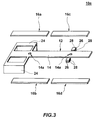
- FIG. 1 is a diagrammatic plan view illustrating one embodiment of the present invention and FIG. 2 is a block diagram of the embodiment shown in FIG. 1.
- a bearing-distance sensor 1 includes a rectangular parallelepiped case 2 for example.
- a first acceleration sensor 10a and a second acceleration sensor 10b are mounted within the case 2.
- the first acceleration sensor 10a detects an acceleration in one direction, e.g. a longitudinal direction of the case 2, to obtain a signal related to that acceleration.
- the second acceleration sensor 10b detects a force applied in a width direction of the case 2, which is perpendicular to said one direction, to obtain a signal related to that force.
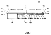
- first acceleration sensor 10a and the second acceleration sensor 10b have the same structure, they have a special structure. Then, the first acceleration sensor 10a will be explained in detail with reference to FIGs. 3 and 4.
- the first acceleration sensor 10a includes a vibrator 12 which vibrates in the longitudinal direction and which includes a strip vibrating member 14 which is created by an elastic invariable metal such as nickel, iron, chrome and titanium or an alloy of them such as an elinver and an iron-nickel alloy.
- the vibrating member 14 may be created by a material such as silica, glass, quartz and ceramic, other than metals which generally generate mechanical vibration.
- Two piezoelectric elements 16a and 16b are formed so as to face from each other on both main surfaces of a part on the side of one end from the center in the longitudinal direction of the vibrating member 14.
- One piezoelectric element 16a includes a piezoelectric layer 18a composed of ceramic for example and electrodes 20a and 22a are formed respectively on both main surfaces of the piezoelectric layer 18a.
- the electrode 20a is adhered on one main surface of the vibrating member 14 by an adhesive for example.
- the other piezoelectric element 16b includes a piezoelectric layer 18b composed of ceramic for example and electrodes 20b and 22b are formed respectively on both main surfaces of the piezoelectric layer 18b.
- the electrode 20b is adhered on the other main surface of the vibrating member 14 by an adhesive for example.
- the piezoelectric layers 18a and 18b of those piezoelectric elements 16a and 16b are polarized from the electrodes 22a and 22b to the electrodes 20a and 20b, i.e. in a thickness direction toward the vibrating member 14 from the outside thereof.
- two piezoelectric elements 16c and 16d are formed so as to face from each other on both main surfaces of a part on the side of the other end from the center in the longitudinal direction of the vibrating member 14.
- One piezoelectric element 16c includes a piezoelectric layer 18c composed of ceramic for example and electrodes 20c and 22c are formed respectively on both main surfaces of the piezoelectric layer 18c.
- the electrode 20c is adhered on one main surface of the vibrating member 14 by an adhesive for example.
- the other piezoelectric element 16d includes a piezoelectric layer 18d composed of ceramic for example and electrodes 20d and 22d are formed respectively on both main surfaces of the piezoelectric layer 18d.
- the electrode 20d is adhered on the other main surface of the vibrating member 14 by an adhesive for example.
- the piezoelectric layers 18c and 18d of those piezoelectric elements 16c and 16d are polarized from the electrodes 20c and 20d to the electrodes 22c and 22d, i.e. in a thickness direction from the vibrating member 14 toward the outside thereof.
- the vibrator 12 vibrates in the longitudinal direction thereof when driving signals having a same phase are applied to the piezoelectric elements 16a through 16d.
- the piezoelectric elements 16a and 16b and the piezoelectric elements 16c and 16d are polarized in the opposite direction each other, they are displaced in the opposite direction each other. Due to that, when a part on the side of one end from the middle of the vibrating member 14 expands in the longitudinal direction, a part on the side of the other end from the middle of the vibrating member 14 in the longitudinal direction contracts as shown by solid line arrows in FIG. 4.
- the vibrating member 14 vibrates at the middle portion of the piezoelectric elements 16a and 16b and the middle portion of the piezoelectric elements 16c and 16d as its nodal portions.
- the vibrating member 14 also vibrates at the both ends in the longitudinal direction as its antinodes.
- Two circular holes 14a for example are created at the two nodal portions of the vibrating member 14 of the vibrator 12. Those two holes 14a increases a deflection of the vibrating member 14 caused by an acceleration and stabilizes the vibration of the vibrating member 14 in the longitudinal direction.
- Two supporting members 24 are formed on the side of one end in the longitudinal direction of the vibrator 12.
- those two supporting members 24 are formed in one body with the vibrating member 14 extending in the width direction from the circumference of the nodal portion on the side of one end of the vibrating member 14 in the longitudinal direction and that extending from the end portion thereof.
- Those supporting members 24 support the portion of the vibrator 12 on the side of one end thereof.
- two mounting members 26 are formed projecting from a distal half of the vibrating member 14.
- the mounting members 26 extend in the width direction from the circumference of the nodal portion on the side of the other end of the vibrating member 14 and are formed in one body with the vibrating member 14.
- Weights 28 are mounted on the both main surfaces of those mounting members 26 by welding or soldering. Those weights 28 increase a deflection of the vibrating member 14 caused by an acceleration.
- the vibrator 12 vibrates in the longitudinal direction as shown by the solid line arrows and the dashed line arrows in FIG. 4 when the side of the one end of the vibrator 12 is supported by fixing the two supporting members 24 and when driving signals having a same phase are applied to the four piezoelectric elements 16a through 16d.
- the vibrating member 14 deflects together with the piezoelectric elements 16a through 16d corresponding to the acceleration and voltages which correspond with the deflection are generated in the piezoelectric elements 16a through 16d. Due to that, the acceleration may be detected by measuring any of the voltages generated in the piezoelectric elements 16a through 16d.
- holes 14a are created respectively at the two nodal portions of the vibrating member 14 in the first acceleration sensor 10a, the deflection of the vibrating member 14 caused by the acceleration is increased and the vibration of the vibrating member 14 in the longitudinal direction is stabilized by keeping the balance of the vibration of the vibrating member 14 in the longitudinal direction. Due to that, an acceleration detecting sensitivity of the first acceleration sensor 10a is improved.
- the weights 28 are mounted to the mounting members 26 near the nodal portion of the vibrator 12 in the first acceleration sensor 10a, the deflection of the vibrating member 14 is increased, the acceleration detecting sensitivity is increased and the vibration of the vibrator 12 is not interfered by the weights 28 since almost no vibration of the vibrator 12 is transmitted to the weights 28.
- each of the circular holes 14a are created respectively at those two nodal portions of the vibrating member 14 in the first acceleration sensor 10a
- the holes created at the nodal portion may have another shape such as a rectangular shape instead of the circular shape and the number of holes created at one nodal portion is not confined to be only one and may be more than two.
- the first acceleration sensor 10a can detect the acceleration also by detecting a difference of voltages generated by the piezoelectric elements 16a and 16b and a difference of voltages generated by the piezoelectric elements 16c and 16d.
- the polarizing direction of the piezoelectric layer of more than one piezoelectric element may be reversed and the phase of driving signal applied to the piezoelectric element whose polarizing direction is reversed may be reversed in the first acceleration sensor 10a.
- the reason why the vibrator is vibrated in the longitudinal direction in the first acceleration sensor 10a is because the vibrator deflects significantly when an acceleration is applied to the vibrator when the vibrator vibrates in the longitudinal direction, thus improving the acceleration detecting sensitivity.
- the supporting member 24 of this first acceleration sensor 10a is fixed within the case 2 so that the main surface of the vibrating member 14 crosses at right angles with the longitudinal direction of the case 2. Accordingly, an acceleration in the longitudinal direction of the case 2 is detected and a signal related to the acceleration is obtained by the first acceleration sensor 10a.
- the supporting member 24 of the second acceleration sensor 10b having the same structure with the first acceleration sensor 10a is also fixed within the case 2 so that the main surface of the vibrating member 14 thereof crosses at right angles with the width direction of the case 2. Accordingly, a force F applied in the width direction of the case 2 is detected and a signal related to the force F is obtained by the second acceleration sensor 10b.
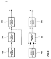
- An output terminal of the first acceleration sensor 10a is connected to an input terminal of a first integrating circuit 30a as shown in FIG. 2.
- the first integrating circuit 30a integrates the output signal of the first acceleration sensor 10a related to the acceleration in the longitudinal direction of the case 2 over time to obtain a signal related to a velocity V in the longitudinal direction of the case 2.
- An output terminal of the first integrating circuit 30a is connected to an input terminal of a second integrating circuit 30b.
- the second integrating circuit 30b integrates the output signal of the first integrating circuit 30a related to the velocity V in the longitudinal direction of the case 2 over time to obtain a signal related to a travel distance L of the vehicle.
- An output terminal of the second acceleration sensor 10b and the output terminal of the first integrating circuit 30a are connected respectively to two input terminals of a first arithmetic circuit 32a.
- the first arithmetic circuit 32a obtains a signal related to a radius of curvature r from the output signal of the second acceleration sensor 10b related to a centrifugal force F applied in the width direction of the case 2 and the output signal of the first integrating circuit 30a related to the velocity V in the longitudinal direction of the case 2.
- An output terminal of the first arithmetic circuit 32a and the output terminal of the first integrating circuit 30a are connected respectively to two input terminals of a second arithmetic circuit 32b.
- An output terminal of the second arithmetic circuit 32b is connected to an input terminal of a third integrating circuit 30c.
- the third integrating circuit 30c integrates the output signal of the second arithmetic circuit 32b related to the angular velocity ⁇ over time to obtain a signal related to a travel bearing ⁇ of the vehicle.
- FIG. 5 shows a relationship among the velocity V at the moving part of the mass m, the radius of curvature r, the angular velocity ⁇ , the centrifugal force F and the travel bearing ⁇ .
- the bearing-distance sensor 1 is mounted in a automobile 40 so that the longitudinal direction and the width direction of the case 2 run parallel respectively with the longitudinal direction and the width direction of the automobile 40 as shown in FIG. 1. Accordingly, the acceleration ⁇ in the longitudinal direction of the automobile 40 is detected and the signal related to the acceleration ⁇ is obtained by the first acceleration sensor 10a. The centrifugal force F applied in the width direction of the automobile 40 is detected and the signal related to the centrifugal force F is obtained by the second acceleration sensor 10b.
- the output signal of the first acceleration sensor 10a related to the acceleration ⁇ in the longitudinal direction of the automobile 40 is integrated over time and the signal related to the velocity V in the longitudinal direction of the automobile 40 is obtained by the first integrating circuit 30a.
- the output signal of the first integrating circuit 30a related to the velocity V in the longitudinal direction of the automobile 40 is integrated over time and the signal related to the travel distance L in the longitudinal direction of the automobile 40 is obtained by the second integrating circuit 30b.
- the signal related to the radius of curvature r is obtained from the output signal of the second acceleration sensor 10b related to the centrifugal force F applied in the width direction of the automobile 40 and the output signal of the first integrating circuit 30a related to the velocity V in the longitudinal direction of the automobile 40.
- the signal related to the angular velocity ⁇ is obtained from the output signal of the first arithmetic circuit 32a related to the radius of curvature r and the output signal of the first integrating circuit 30a related to the velocity V in the longitudinal direction of the automobile 40.
- the output signal of the second arithmetic circuit 32b related to the angular velocity ⁇ is integrated over time and the signal related to the travel bearing ⁇ of the automobile 40 is obtained by the third integrating circuit 30c.
- this bearing-distance sensor 1 can detect the travel bearing ⁇ and the travel distance L of the automobile 40.
- FIG. 6 is a block diagram showing another embodiment of the present invention.
- one arithmetic circuit 32 is provided instead of the first arithmetic circuit 32a and the second arithmetic circuit 32b provided in the embodiment shown in FIGs. 1 and 2.
- the output terminals of the second acceleration sensor 10b and the first integrating circuit 30a are connected respectively to two input terminals of the arithmetic circuit 32.
- An output terminal of the arithmetic circuit 32 is connected to the input terminal of the third integrating circuit 30c as another integrating circuit.
- the arithmetic circuit 32 obtains a signal related to the angular velocity ⁇ from the output signal of the second acceleration sensor 10b related to the centrifugal force F applied in the width direction of the case 2 and the output signal of the first integrating circuit 30a related to the velocity V in the longitudinal direction of the case 2.
- the embodiment shown in FIG. 6 can detect a travel bearing and a travel distance of a vehicle such as an automobile and can be small and inexpensive, similarly to the embodiment shown in FIGs. 1 and 2. Note that the circuit structure of the embodiment shown in FIG. 6 may be simplified as compared to the embodiment shown in FIGs. 1 and 2 because one arithmetic circuit is decreased.
- angular velocity sensors having special structures respectively as the first acceleration sensor and the second acceleration sensor are used in each embodiment described above, an angular velocity sensor having another structure may be used in the present invention.
- a bearing sensor which can detect only the travel bearing ⁇ of the vehicle may be constructed if the second integrating circuit 30b is removed in each embodiment shown in FIGs. 2 and 6.
- the bearing sensor can be small and inexpensive because no expensive vibratory gyroscope is used and two acceleration sensors need not be disposed with a wide space therebetween.
- the travel bearing ⁇ of the vehicle may be readily detected by just adding one acceleration sensor having the simple structure as shown in each embodiment described above if a signal (which corresponds to the velocity V output from the first integrating circuit 30a) obtained from a speed sensor conventionally mounted in a vehicle such as an automobile.
- a signal which corresponds to the velocity V output from the first integrating circuit 30a
- a speed sensor conventionally mounted in a vehicle such as an automobile.
Abstract
Description
- The present invention relates generally to a bearing sensor and a bearing-distance sensor and more particularly to a bearing sensor and a bearing-distance sensor used for a car navigation system for example and capable of detecting a travel bearing of a vehicle and of detecting a travel bearing and a travel distance of the vehicle, respectively.
- Hitherto, there exists a car navigation system using a bearing sensor for detecting travel bearing and a distance sensor for detecting travel distance. There are also two types of bearing sensors; one using a vibratory gyroscope and another wherein two acceleration sensors are disposed horizontally with a wide space therebetween. The bearing sensor using the vibratory gyroscope detects an angular velocity of rotation by the vibratory gyroscope and finds a travel bearing from the angular velocity of rotation. The bearing sensor in which two acceleration sensors are disposed horizontally detects accelerations of two parts by those two acceleration sensors and finds a travel bearing from a difference of those accelerations.
- However, because the vibratory gyroscope is expensive, the whole system of the navigation system having the bearing sensor using the vibratory gyroscope becomes also expensive.
- Meanwhile, a size of the navigation system having the bearing sensor in which two acceleration sensors are disposed horizontally becomes large because those two acceleration sensors have to be disposed horizontally with an adequate space within the system.
- Accordingly, it is an object of the present invention to provide a small and inexpensive bearing sensor which can detect a travel bearing of a vehicle.
- It is another object of the present invention to provide a small and inexpensive bearing-distance sensor which can detect a travel bearing and a travel distance of a vehicle.
- A bearing sensor of the present invention comprises a first acceleration sensor for detecting an acceleration in one direction to obtain a signal related to the acceleration in said one direction and a second acceleration sensor for detecting a force applied in a direction perpendicular to said one direction to obtain a signal related to the force applied in the direction perpendicular to said one direction and finds a travel bearing of a vehicle from the output signals of the first and second acceleration sensors.
- In the bearing sensor of the present invention, the travel bearing of the vehicle is found from the output signals of the first and second acceleration sensors by using a first integrating circuit for integrating the output signal of the first acceleration sensor over time to obtain a signal related to a velocity in one direction; a first arithmetic circuit for obtaining a signal related to a radius of curvature from the output signal of the second acceleration sensor and the output signal of the first integrating circuit; a second arithmetic circuit for obtaining a signal related to an angular velocity from the output signal of the first arithmetic circuit and the output signal of the first integrating circuit; and another integrating circuit for integrating the output signal of the second arithmetic circuit over time to obtain a signal related to the travel bearing of the vehicle.
- Or, it is found by using the first integrating circuit for integrating the output signal of the first acceleration sensor over time to obtain the signal related to the velocity in one direction; an arithmetic circuit for obtaining a signal related to an angular velocity from the output signal of the second acceleration sensor and the output signal of the first integrating circuit; and another integrating circuit for integrating the output signal of the arithmetic circuit over time to obtain a signal related to the travel bearing of the vehicle.
- A bearing-distance sensor of the present invention comprises a first acceleration sensor for detecting an acceleration in one direction to obtain a signal related to the acceleration in said one direction and a second acceleration sensor for detecting a force applied in a direction perpendicular to said one direction to obtain a signal related to the force applied in the direction perpendicular to said one direction. The sensor finds a travel distance of a vehicle from the output signal of the first acceleration sensor and finds a travel bearing of the vehicle from the output signals of the first and second acceleration sensors.
- In the bearing-distance sensor of the present invention, the travel distance of the vehicle is found from the output signal of the first acceleration sensor by using a first integrating circuit for integrating the output signal of the first acceleration sensor over time to obtain a signal related to a velocity in one direction and a second integrating circuit for integrating the output signal of the first integrating circuit over time to obtain a signal related to the travel distance of the vehicle.
- Further, in the bearing-distance sensor of the present invention, the travel bearing of the vehicle is found from the output signals of the first and second acceleration sensors by using the first integrating circuit for integrating the output signal of the first acceleration sensor over time to obtain the signal related to the velocity in one direction; a first arithmetic circuit for obtaining a signal related to a radius of curvature from the output signal of the second acceleration sensor and the output signal of the first integrating circuit; a second arithmetic circuit for obtaining a signal related to an angular velocity from the output signal of the first arithmetic circuit and the output signal of the first integrating circuit; and a third integrating circuit for integrating the output signal of the second arithmetic circuit over time to obtain a signal related to the travel bearing of the vehicle.
- Or, it is found by using the first integrating circuit for integrating the output signal of the first acceleration sensor over time to obtain the signal related to the velocity in one direction; the arithmetic circuit for obtaining the signal related to the angular velocity from the output signal of the second acceleration sensor and the output signal of the first integrating circuit; and the third integrating circuit for integrating the output signal of the arithmetic circuit over time to obtain the signal related to the travel bearing of the vehicle.
- In the bearing sensor and the bearing-distance sensor of the present invention, an acceleration in one direction is detected and a signal related to the acceleration in said one direction is obtained by the first acceleration sensor. A force applied in a direction perpendicular to said one direction is detected and a signal related to the force applied in the direction perpendicular to said one direction is obtained by the second acceleration sensor.
- In the bearing sensor of the present invention, a travel bearing of the vehicle is found from the output signals of the first and second acceleration sensors.
- In the bearing-distance sensor of the present invention, a travel distance of the vehicle is found from the output signal of the first acceleration sensor and a travel bearing of the vehicle is found from the output signals of the first and second acceleration sensors.
- Accordingly, the present invention can realize a small and inexpensive bearing sensor capable of detecting the travel bearing of the vehicle because no expensive vibratory gyroscope needs to be used and two acceleration sensors need not to be disposed with a wide space therebetween to detect the travel bearing of the vehicle.
- Further, the present invention can realize a small and inexpensive bearing-distance sensor capable of detecting the travel bearing and travel distance of the vehicle because no expensive vibratory gyroscope needs to be used and two acceleration sensors need not to be disposed with a wide space therebetween to detect the travel bearing and the travel distance of the vehicle.
- Therefore, the present invention allows a miniaturization and reduction of cost of a system such as a navigation system which requires the bearing sensor and the distance sensor.
- The above and other related objects and features of the present invention will be apparent from a reading of the following detailed description of preferred embodiments made with reference to the accompanying drawings.
-
- FIG. 1
- is a diagrammatic plan view illustrating one preferred embodiment of the present invention;
- FIG. 2
- is a block diagram of the embodiment shown in FIG. 1;
- FIG. 3
- is an exploded perspective view illustrating an acceleration sensor used in the embodiment shown in FIG. 1;
- FIG. 4
- is a side view of the acceleration sensor used in the embodiment shown in FIG. 1;
- FIG. 5
- is a graph showing a relationship among a velocity V at moving part of a mass m, a radius of curvature r, an angular velocity ω, a centrifugal force F and a travel bearing Θ; and
- FIG. 6
- is a block diagram illustrating another embodiment of the present invention.
- Preferred embodiments of the present invention will be explained below with reference to the drawings.
- FIG. 1 is a diagrammatic plan view illustrating one embodiment of the present invention and FIG. 2 is a block diagram of the embodiment shown in FIG. 1. A bearing-
distance sensor 1 includes a rectangularparallelepiped case 2 for example. - In the figure, a
first acceleration sensor 10a and asecond acceleration sensor 10b are mounted within thecase 2. Thefirst acceleration sensor 10a detects an acceleration in one direction, e.g. a longitudinal direction of thecase 2, to obtain a signal related to that acceleration. Thesecond acceleration sensor 10b detects a force applied in a width direction of thecase 2, which is perpendicular to said one direction, to obtain a signal related to that force. - While the
first acceleration sensor 10a and thesecond acceleration sensor 10b have the same structure, they have a special structure. Then, thefirst acceleration sensor 10a will be explained in detail with reference to FIGs. 3 and 4. - The
first acceleration sensor 10a includes avibrator 12 which vibrates in the longitudinal direction and which includes astrip vibrating member 14 which is created by an elastic invariable metal such as nickel, iron, chrome and titanium or an alloy of them such as an elinver and an iron-nickel alloy. Note that the vibratingmember 14 may be created by a material such as silica, glass, quartz and ceramic, other than metals which generally generate mechanical vibration. - Two
piezoelectric elements member 14. Onepiezoelectric element 16a includes apiezoelectric layer 18a composed of ceramic for example andelectrodes piezoelectric layer 18a. Theelectrode 20a is adhered on one main surface of the vibratingmember 14 by an adhesive for example. Similarly, the otherpiezoelectric element 16b includes apiezoelectric layer 18b composed of ceramic for example andelectrodes piezoelectric layer 18b. Theelectrode 20b is adhered on the other main surface of the vibratingmember 14 by an adhesive for example. Thepiezoelectric layers piezoelectric elements electrodes electrodes member 14 from the outside thereof. - Further, two
piezoelectric elements member 14. Onepiezoelectric element 16c includes apiezoelectric layer 18c composed of ceramic for example andelectrodes piezoelectric layer 18c. Theelectrode 20c is adhered on one main surface of the vibratingmember 14 by an adhesive for example. Similarly, the otherpiezoelectric element 16d includes apiezoelectric layer 18d composed of ceramic for example andelectrodes piezoelectric layer 18d. Theelectrode 20d is adhered on the other main surface of the vibratingmember 14 by an adhesive for example. Thepiezoelectric layers piezoelectric elements electrodes electrodes member 14 toward the outside thereof. - The
vibrator 12 vibrates in the longitudinal direction thereof when driving signals having a same phase are applied to thepiezoelectric elements 16a through 16d. In this case, because thepiezoelectric elements piezoelectric elements member 14 expands in the longitudinal direction, a part on the side of the other end from the middle of the vibratingmember 14 in the longitudinal direction contracts as shown by solid line arrows in FIG. 4. Contrary to that, when the part on the side of one end from the middle of the vibratingmember 14 contracts in the longitudinal direction, the part on the side of the other end from the middle of the vibratingmember 14 in the longitudinal direction expands as shown by dashed line arrows in FIG. 4. A distance between the both ends of the vibratingmember 14 in the longitudinal direction barely changes in this case because the degree of expansion/contraction of the part on the side of one end from the middle of the vibratingmember 14 in the longitudinal direction is canceled by the degree of expansion/contraction of the part on the other end from the middle of the vibratingmember 14 in the longitudinal direction. The vibratingmember 14 vibrates at the middle portion of thepiezoelectric elements piezoelectric elements member 14 also vibrates at the both ends in the longitudinal direction as its antinodes. - Two
circular holes 14a for example are created at the two nodal portions of the vibratingmember 14 of thevibrator 12. Those twoholes 14a increases a deflection of the vibratingmember 14 caused by an acceleration and stabilizes the vibration of the vibratingmember 14 in the longitudinal direction. - Two supporting
members 24 are formed on the side of one end in the longitudinal direction of thevibrator 12. In this case, those two supportingmembers 24 are formed in one body with the vibratingmember 14 extending in the width direction from the circumference of the nodal portion on the side of one end of the vibratingmember 14 in the longitudinal direction and that extending from the end portion thereof. Those supportingmembers 24 support the portion of thevibrator 12 on the side of one end thereof. - Further, two mounting
members 26 are formed projecting from a distal half of the vibratingmember 14. In this case, the mountingmembers 26 extend in the width direction from the circumference of the nodal portion on the side of the other end of the vibratingmember 14 and are formed in one body with the vibratingmember 14.Weights 28 are mounted on the both main surfaces of those mountingmembers 26 by welding or soldering. Thoseweights 28 increase a deflection of the vibratingmember 14 caused by an acceleration. - In the
first acceleration sensor 10a, thevibrator 12 vibrates in the longitudinal direction as shown by the solid line arrows and the dashed line arrows in FIG. 4 when the side of the one end of thevibrator 12 is supported by fixing the two supportingmembers 24 and when driving signals having a same phase are applied to the fourpiezoelectric elements 16a through 16d. - Then, when an acceleration is applied to the vibrating
member 14 of thevibrator 12 in the direction perpendicular to the main surface thereof, the vibratingmember 14 deflects together with thepiezoelectric elements 16a through 16d corresponding to the acceleration and voltages which correspond with the deflection are generated in thepiezoelectric elements 16a through 16d. Due to that, the acceleration may be detected by measuring any of the voltages generated in thepiezoelectric elements 16a through 16d. - Further, because
holes 14a are created respectively at the two nodal portions of the vibratingmember 14 in thefirst acceleration sensor 10a, the deflection of the vibratingmember 14 caused by the acceleration is increased and the vibration of the vibratingmember 14 in the longitudinal direction is stabilized by keeping the balance of the vibration of the vibratingmember 14 in the longitudinal direction. Due to that, an acceleration detecting sensitivity of thefirst acceleration sensor 10a is improved. - Further, because the
weights 28 are mounted to the mountingmembers 26 near the nodal portion of thevibrator 12 in thefirst acceleration sensor 10a, the deflection of the vibratingmember 14 is increased, the acceleration detecting sensitivity is increased and the vibration of thevibrator 12 is not interfered by theweights 28 since almost no vibration of thevibrator 12 is transmitted to theweights 28. - Note that although each of the
circular holes 14a are created respectively at those two nodal portions of the vibratingmember 14 in thefirst acceleration sensor 10a, the holes created at the nodal portion may have another shape such as a rectangular shape instead of the circular shape and the number of holes created at one nodal portion is not confined to be only one and may be more than two. - The
first acceleration sensor 10a can detect the acceleration also by detecting a difference of voltages generated by thepiezoelectric elements piezoelectric elements - Further, the polarizing direction of the piezoelectric layer of more than one piezoelectric element may be reversed and the phase of driving signal applied to the piezoelectric element whose polarizing direction is reversed may be reversed in the
first acceleration sensor 10a. - The reason why the vibrator is vibrated in the longitudinal direction in the
first acceleration sensor 10a is because the vibrator deflects significantly when an acceleration is applied to the vibrator when the vibrator vibrates in the longitudinal direction, thus improving the acceleration detecting sensitivity. - The supporting
member 24 of thisfirst acceleration sensor 10a is fixed within thecase 2 so that the main surface of the vibratingmember 14 crosses at right angles with the longitudinal direction of thecase 2. Accordingly, an acceleration in the longitudinal direction of thecase 2 is detected and a signal related to the acceleration is obtained by thefirst acceleration sensor 10a. - The supporting
member 24 of thesecond acceleration sensor 10b having the same structure with thefirst acceleration sensor 10a is also fixed within thecase 2 so that the main surface of the vibratingmember 14 thereof crosses at right angles with the width direction of thecase 2. Accordingly, a force F applied in the width direction of thecase 2 is detected and a signal related to the force F is obtained by thesecond acceleration sensor 10b. - An output terminal of the
first acceleration sensor 10a is connected to an input terminal of a first integratingcircuit 30a as shown in FIG. 2. The first integratingcircuit 30a integrates the output signal of thefirst acceleration sensor 10a related to the acceleration in the longitudinal direction of thecase 2 over time to obtain a signal related to a velocity V in the longitudinal direction of thecase 2. - An output terminal of the first integrating
circuit 30a is connected to an input terminal of a second integratingcircuit 30b. The second integratingcircuit 30b integrates the output signal of the first integratingcircuit 30a related to the velocity V in the longitudinal direction of thecase 2 over time to obtain a signal related to a travel distance L of the vehicle. - An output terminal of the
second acceleration sensor 10b and the output terminal of the first integratingcircuit 30a are connected respectively to two input terminals of a firstarithmetic circuit 32a. The firstarithmetic circuit 32a obtains a signal related to a radius of curvature r from the output signal of thesecond acceleration sensor 10b related to a centrifugal force F applied in the width direction of thecase 2 and the output signal of the first integratingcircuit 30a related to the velocity V in the longitudinal direction of thecase 2. Note that the firstarithmetic circuit 32a may be realized from a relationship of
- An output terminal of the first
arithmetic circuit 32a and the output terminal of the first integratingcircuit 30a are connected respectively to two input terminals of a secondarithmetic circuit 32b. The secondarithmetic circuit 32b obtains a signal related to an angular velocity · from the output signal of the firstarithmetic circuit 32a related to the radius of curvature r and from the output signal of the first integratingcircuit 30a related to the velocity V in the longitudinal direction of thecase 2. Note that this secondarithmetic circuit 32b may be realized from a relationship of
- An output terminal of the second
arithmetic circuit 32b is connected to an input terminal of a third integratingcircuit 30c. The third integratingcircuit 30c integrates the output signal of the secondarithmetic circuit 32b related to the angular velocity · over time to obtain a signal related to a travel bearing Θ of the vehicle. - FIG. 5 shows a relationship among the velocity V at the moving part of the mass m, the radius of curvature r, the angular velocity ω, the centrifugal force F and the travel bearing Θ.
- The bearing-
distance sensor 1 is mounted in aautomobile 40 so that the longitudinal direction and the width direction of thecase 2 run parallel respectively with the longitudinal direction and the width direction of theautomobile 40 as shown in FIG. 1. Accordingly, the acceleration α in the longitudinal direction of theautomobile 40 is detected and the signal related to the acceleration α is obtained by thefirst acceleration sensor 10a. The centrifugal force F applied in the width direction of theautomobile 40 is detected and the signal related to the centrifugal force F is obtained by thesecond acceleration sensor 10b. - Further, the output signal of the
first acceleration sensor 10a related to the acceleration α in the longitudinal direction of theautomobile 40 is integrated over time and the signal related to the velocity V in the longitudinal direction of theautomobile 40 is obtained by the first integratingcircuit 30a. - The output signal of the first integrating
circuit 30a related to the velocity V in the longitudinal direction of theautomobile 40 is integrated over time and the signal related to the travel distance L in the longitudinal direction of theautomobile 40 is obtained by the second integratingcircuit 30b. - The signal related to the radius of curvature r is obtained from the output signal of the
second acceleration sensor 10b related to the centrifugal force F applied in the width direction of theautomobile 40 and the output signal of the first integratingcircuit 30a related to the velocity V in the longitudinal direction of theautomobile 40. - The signal related to the angular velocity ω is obtained from the output signal of the first
arithmetic circuit 32a related to the radius of curvature r and the output signal of the first integratingcircuit 30a related to the velocity V in the longitudinal direction of theautomobile 40. - Then the output signal of the second
arithmetic circuit 32b related to the angular velocity ω is integrated over time and the signal related to the travel bearing Θ of theautomobile 40 is obtained by the third integratingcircuit 30c. - Accordingly, this bearing-
distance sensor 1 can detect the travel bearing Θ and the travel distance L of theautomobile 40. - Further, because no expensive vibratory gyroscope is used and two acceleration sensors need not be disposed with a wide space therebetween in the bearing-
distance sensor 1, it can be small and inexpensive. - FIG. 6 is a block diagram showing another embodiment of the present invention. In the embodiment shown in FIG. 6, one
arithmetic circuit 32 is provided instead of the firstarithmetic circuit 32a and the secondarithmetic circuit 32b provided in the embodiment shown in FIGs. 1 and 2. The output terminals of thesecond acceleration sensor 10b and the first integratingcircuit 30a are connected respectively to two input terminals of thearithmetic circuit 32. An output terminal of thearithmetic circuit 32 is connected to the input terminal of the third integratingcircuit 30c as another integrating circuit. Thearithmetic circuit 32 obtains a signal related to the angular velocity · from the output signal of thesecond acceleration sensor 10b related to the centrifugal force F applied in the width direction of thecase 2 and the output signal of the first integratingcircuit 30a related to the velocity V in the longitudinal direction of thecase 2. Thisarithmetic circuit 32 is realized from a relationship of
- The embodiment shown in FIG. 6 can detect a travel bearing and a travel distance of a vehicle such as an automobile and can be small and inexpensive, similarly to the embodiment shown in FIGs. 1 and 2. Note that the circuit structure of the embodiment shown in FIG. 6 may be simplified as compared to the embodiment shown in FIGs. 1 and 2 because one arithmetic circuit is decreased.
- Note that although the angular velocity sensors having special structures respectively as the first acceleration sensor and the second acceleration sensor are used in each embodiment described above, an angular velocity sensor having another structure may be used in the present invention.
- A bearing sensor which can detect only the travel bearing Θ of the vehicle may be constructed if the second integrating
circuit 30b is removed in each embodiment shown in FIGs. 2 and 6. In this case, the bearing sensor can be small and inexpensive because no expensive vibratory gyroscope is used and two acceleration sensors need not be disposed with a wide space therebetween. - Further, the travel bearing Θ of the vehicle may be readily detected by just adding one acceleration sensor having the simple structure as shown in each embodiment described above if a signal (which corresponds to the velocity V output from the first integrating
circuit 30a) obtained from a speed sensor conventionally mounted in a vehicle such as an automobile. As a result, an inexpensive navigation system may be readily realized. - While preferred embodiments have been described, variations thereto will occur to those skilled in the art within the scope of the present inventive concepts which are delineated by the following claims.
Claims (6)
- A bearing sensor (1), comprising:
a first acceleration sensor (10a) for detecting an acceleration (α) in one direction to obtain a signal related to the acceleration (α) in said one direction; and
a second acceleration sensor (10b) for detecting a force (F) applied in a direction perpendicular to said one direction to obtain a signal related to the force (F) applied in the direction perpendicular to said one direction;
said sensor (1) finding a travel bearing (Θ) of a vehicle (40) from the output signals of said first (10a) and second (10b) acceleration sensors. - The bearing sensor (1) according to Claim 1, comprising:
a first integrating circuit (30a) for integrating the output signal of said first acceleration sensor (10a) over time to obtain a signal related to a velocity (V) in said one direction;
a first arithmetic circuit (32a) for obtaining a signal related to a radius (r) of curvature from the output signal of said second acceleration sensor (10b) and the output signal of said first integrating circuit (30a);
a second arithmetic circuit (30b) for obtaining a signal related to an angular velocity (ω) from the output signal of said first arithmetic circuit (32a) and the output signal of said first integrating circuit (30a); and
another integrating circuit (30c) for integrating the output signal of said second arithmetic circuit (32b) over time to obtain a signal related to the travel bearing (Θ) of said vehicle (40). - The bearing sensor (1) according to Claim 1, comprising:
a first integrating circuit (30a) for integrating the output signal of said first acceleration sensor (10a) over time to obtain a signal related to a velocity (V) in said one direction;
an arithmetic circuit (32) for obtaining a signal related to an angular velocity (ω) from the output signal of said second acceleration sensor (10b) and the output signal of said first integrating circuit (30a); and
another integrating circuit (30c) for integrating the output signal of said arithmetic circuit (32) over time to obtain a signal related to the travel bearing (Θ) of said vehicle (40). - A bearing-distance sensor (1), comprising:
a first acceleration sensor (10a) for detecting an acceleration (α) in one direction to obtain a signal related to the acceleration (α) in said one direction; and
a second acceleration sensor (10b) for detecting a force (F) applied in the direction perpendicular to said one direction to obtain a signal related to the force (F) applied in the direction perpendicular to said one direction:
said sensor (1) finding a travel distance (L) of a vehicle (40) from the output signal of said first acceleration sensor (10a) and finding a travel bearing (Θ) of the vehicle (40) from the output signal of said first acceleration sensor (10a) and the output signal of said second acceleration sensor (10b). - The bearing-distance sensor (1) according to Claim 4, comprising:
a first integrating circuit (30a) for integrating the output signal of said first acceleration sensor (10a) over time to obtain a signal related to a velocity (V) in said one direction;
a second integrating circuit (30b) for integrating the output signal of said first integrating circuit (30a) to obtain a signal related to a travel distance (L) of said vehicle (40);
a first arithmetic circuit (32a) for obtaining a signal related to a radius (r) of curvature from the output signal of said second acceleration sensor (10b) and the output signal of said first integrating circuit (30a);
a second arithmetic circuit (32b) for obtaining a signal related to an angular velocity (ω) from the output signal of said first arithmetic circuit (32a) and the output signal of said first integrating circuit (30a); and
a third integrating circuit (30c) for integrating the output signal of said second arithmetic circuit (32b) over time to obtain a signal related to the travel bearing (Θ) of said vehicle (40). - The bearing-distance sensor (1) according to Claim 4, comprising:
a first integrating circuit (30a) for integrating the output signal of said first acceleration sensor (10a) over time to obtain a signal related to a velocity (V) in said one direction;
a second integrating circuit (30b) for integrating the output signal of said first integrating circuit (30a) to obtain a signal related to a travel distance (L) of said vehicle (40);
an arithmetic circuit (32) for obtaining a signal related to an angular velocity (ω) from the output signal of said second acceleration sensor (10b) and the output signal of said first integrating circuit (30a); and
a third integrating circuit (30c) for integrating the output signal of said arithmetic circuit (32) over time to obtain a signal related to the travel bearing (Θ) of said vehicle (40).
Applications Claiming Priority (6)
| Application Number | Priority Date | Filing Date | Title |
|---|---|---|---|
| JP266367/94 | 1994-10-04 | ||
| JP26636794 | 1994-10-04 | ||
| JP26636794 | 1994-10-04 | ||
| JP6309993A JPH08159806A (en) | 1994-10-04 | 1994-11-17 | Azimuth sensor aand azimuth/distance sensor |
| JP309993/94 | 1994-11-17 | ||
| JP30999394 | 1994-11-17 |
Publications (2)
| Publication Number | Publication Date |
|---|---|
| EP0706030A1 true EP0706030A1 (en) | 1996-04-10 |
| EP0706030B1 EP0706030B1 (en) | 2000-07-05 |
Family
ID=26547406
Family Applications (1)
| Application Number | Title | Priority Date | Filing Date |
|---|---|---|---|
| EP95115652A Expired - Lifetime EP0706030B1 (en) | 1994-10-04 | 1995-10-04 | Bearing sensor and bearing-distance sensor |
Country Status (4)
| Country | Link |
|---|---|
| US (1) | US5597954A (en) |
| EP (1) | EP0706030B1 (en) |
| JP (1) | JPH08159806A (en) |
| DE (1) | DE69517766T2 (en) |
Families Citing this family (12)
| Publication number | Priority date | Publication date | Assignee | Title |
|---|---|---|---|---|
| KR0154271B1 (en) * | 1995-11-07 | 1998-12-01 | 정몽원 | Checker of moving of an automobile |
| JPH10132843A (en) * | 1996-10-25 | 1998-05-22 | Murata Mfg Co Ltd | Velocity operating equipment |
| US6629462B2 (en) * | 2000-07-24 | 2003-10-07 | Matsushita Electric Industrial Co., Ltd. | Acceleration sensor, an acceleration detection apparatus, and a positioning device |
| US6575031B2 (en) * | 2001-01-26 | 2003-06-10 | Mts Systems Corporation | Transducer for measuring displacement of a vehicle spindle |
| US20040078446A1 (en) * | 2002-09-17 | 2004-04-22 | Daniell W. Todd | Options associated with instant messaging (IM) chat transcripts of IM chat sessions |
| WO2004036377A2 (en) | 2002-10-15 | 2004-04-29 | Medtronic Inc. | Configuring and testing treatment therapy parameters for a medical device system |
| US7146211B2 (en) * | 2002-10-15 | 2006-12-05 | Medtronic, Inc. | Signal quality monitoring and control for a medical device system |
| US8738136B2 (en) * | 2002-10-15 | 2014-05-27 | Medtronic, Inc. | Clustering of recorded patient neurological activity to determine length of a neurological event |
| EP1629341A4 (en) * | 2002-10-15 | 2008-10-15 | Medtronic Inc | Multi-modal operation of a medical device system |
| AU2003287166A1 (en) * | 2002-10-15 | 2004-05-04 | Medtronic Inc. | Phase shifting of neurological signals in a medical device system |
| JP2008089517A (en) * | 2006-10-04 | 2008-04-17 | Sony Corp | Azimuth discrimination device, azimuth discrimination method, and azimuth discrimination program |
| JP2009288022A (en) * | 2008-05-28 | 2009-12-10 | Sumitomo Electric Ind Ltd | Abnormality determination device of earth magnetism sensor, travel azimuth specification device, computer program, and abnormality determination method of earth magnetism sensor |
Citations (1)
| Publication number | Priority date | Publication date | Assignee | Title |
|---|---|---|---|---|
| US4393709A (en) * | 1980-11-13 | 1983-07-19 | Alps Electric Co., Ltd. | Direction detection apparatus |
Family Cites Families (6)
| Publication number | Priority date | Publication date | Assignee | Title |
|---|---|---|---|---|
| DE2818202C2 (en) * | 1978-04-26 | 1987-03-26 | Bodenseewerk Gerätetechnik GmbH, 7770 Überlingen | Navigation device for land, air or sea vehicles |
| US4590801A (en) * | 1983-09-02 | 1986-05-27 | Sundstrand Data Control, Inc. | Apparatus for measuring inertial specific force and angular rate of a moving body |
| GB2146776B (en) * | 1983-09-16 | 1986-07-30 | Ferranti Plc | Accelerometer systems |
| US4711125A (en) * | 1985-11-06 | 1987-12-08 | Morrison Melvin M | Inertial measurement unit |
| JP2657581B2 (en) * | 1990-11-28 | 1997-09-24 | 本田技研工業株式会社 | Current position display device of moving object |
| DE69219006T2 (en) * | 1991-05-21 | 1997-11-13 | Matsushita Electric Ind Co Ltd | Vehicle position determining device |
-
1994
- 1994-11-17 JP JP6309993A patent/JPH08159806A/en active Pending
-
1995
- 1995-10-04 EP EP95115652A patent/EP0706030B1/en not_active Expired - Lifetime
- 1995-10-04 US US08/539,133 patent/US5597954A/en not_active Expired - Fee Related
- 1995-10-04 DE DE69517766T patent/DE69517766T2/en not_active Expired - Fee Related
Patent Citations (1)
| Publication number | Priority date | Publication date | Assignee | Title |
|---|---|---|---|---|
| US4393709A (en) * | 1980-11-13 | 1983-07-19 | Alps Electric Co., Ltd. | Direction detection apparatus |
Also Published As
| Publication number | Publication date |
|---|---|
| US5597954A (en) | 1997-01-28 |
| DE69517766T2 (en) | 2001-03-01 |
| DE69517766D1 (en) | 2000-08-10 |
| JPH08159806A (en) | 1996-06-21 |
| EP0706030B1 (en) | 2000-07-05 |
Similar Documents
| Publication | Publication Date | Title |
|---|---|---|
| US4750364A (en) | Angular velocity and acceleration sensor | |
| EP0614087B1 (en) | Piezoelectric vibrator and acceleration sensor using the same | |
| JP3151927B2 (en) | Acceleration sensor | |
| US6046531A (en) | Vibrator, vibratory gyroscope, and linear accelerometer | |
| EP0706030A1 (en) | Bearing and distance sensor | |
| EP0936440B1 (en) | Vibrators, vibratory gyroscopes, a method of detecting a turning angular rate and linear accelerometer | |
| JPH07306048A (en) | Piezoelectric vibrator | |
| JP3741041B2 (en) | Vibrating gyro and electronic device using the same | |
| JP3166522B2 (en) | Acceleration sensor | |
| US5578754A (en) | Vibration-type angular-velocity sensor | |
| JP3139205B2 (en) | Acceleration sensor | |
| EP0732566B1 (en) | Vibrating gyroscope | |
| EP0684450B1 (en) | Supporting structure of vibrator | |
| JP3139204B2 (en) | Acceleration sensor | |
| JP3129116B2 (en) | Acceleration sensor | |
| JP3139212B2 (en) | Acceleration sensor | |
| US6092417A (en) | Gyrosensor | |
| JP3129117B2 (en) | Acceleration sensor | |
| EP0563762B1 (en) | Vibratory gyroscope with piezoelectric elements in vicinities of nodal points | |
| JP3129022B2 (en) | Acceleration sensor | |
| JP3139211B2 (en) | Acceleration sensor | |
| JPS6246266A (en) | Oscillation sensor | |
| JPH10339739A (en) | Inertia sensor | |
| JPH0695098B2 (en) | Vibrating gyro | |
| JP3304722B2 (en) | Vibrating gyro |
Legal Events
| Date | Code | Title | Description |
|---|---|---|---|
| PUAI | Public reference made under article 153(3) epc to a published international application that has entered the european phase |
Free format text: ORIGINAL CODE: 0009012 |
|
| 17P | Request for examination filed |
Effective date: 19951004 |
|
| AK | Designated contracting states |
Kind code of ref document: A1 Designated state(s): DE FR GB IT SE |
|
| 17Q | First examination report despatched |
Effective date: 19980324 |
|
| GRAG | Despatch of communication of intention to grant |
Free format text: ORIGINAL CODE: EPIDOS AGRA |
|
| RTI1 | Title (correction) |
Free format text: BEARING SENSOR AND BEARING-DISTANCE SENSOR |
|
| GRAG | Despatch of communication of intention to grant |
Free format text: ORIGINAL CODE: EPIDOS AGRA |
|
| GRAG | Despatch of communication of intention to grant |
Free format text: ORIGINAL CODE: EPIDOS AGRA |
|
| GRAH | Despatch of communication of intention to grant a patent |
Free format text: ORIGINAL CODE: EPIDOS IGRA |
|
| GRAH | Despatch of communication of intention to grant a patent |
Free format text: ORIGINAL CODE: EPIDOS IGRA |
|
| GRAA | (expected) grant |
Free format text: ORIGINAL CODE: 0009210 |
|
| AK | Designated contracting states |
Kind code of ref document: B1 Designated state(s): DE FR GB IT SE |
|
| ITF | It: translation for a ep patent filed |
Owner name: JACOBACCI & PERANI S.P.A. |
|
| REF | Corresponds to: |
Ref document number: 69517766 Country of ref document: DE Date of ref document: 20000810 |
|
| ET | Fr: translation filed | ||
| PLBE | No opposition filed within time limit |
Free format text: ORIGINAL CODE: 0009261 |
|
| STAA | Information on the status of an ep patent application or granted ep patent |
Free format text: STATUS: NO OPPOSITION FILED WITHIN TIME LIMIT |
|
| 26N | No opposition filed | ||
| REG | Reference to a national code |
Ref country code: GB Ref legal event code: IF02 |
|
| PGFP | Annual fee paid to national office [announced via postgrant information from national office to epo] |
Ref country code: DE Payment date: 20070927 Year of fee payment: 13 |
|
| PGFP | Annual fee paid to national office [announced via postgrant information from national office to epo] |
Ref country code: IT Payment date: 20071026 Year of fee payment: 13 |
|
| PGFP | Annual fee paid to national office [announced via postgrant information from national office to epo] |
Ref country code: SE Payment date: 20071004 Year of fee payment: 13 |
|
| PGFP | Annual fee paid to national office [announced via postgrant information from national office to epo] |
Ref country code: GB Payment date: 20071003 Year of fee payment: 13 Ref country code: FR Payment date: 20071009 Year of fee payment: 13 |
|
| EUG | Se: european patent has lapsed | ||
| GBPC | Gb: european patent ceased through non-payment of renewal fee |
Effective date: 20081004 |
|
| REG | Reference to a national code |
Ref country code: FR Ref legal event code: ST Effective date: 20090630 |
|
| PG25 | Lapsed in a contracting state [announced via postgrant information from national office to epo] |
Ref country code: IT Free format text: LAPSE BECAUSE OF NON-PAYMENT OF DUE FEES Effective date: 20081004 Ref country code: DE Free format text: LAPSE BECAUSE OF NON-PAYMENT OF DUE FEES Effective date: 20090501 |
|
| PG25 | Lapsed in a contracting state [announced via postgrant information from national office to epo] |
Ref country code: FR Free format text: LAPSE BECAUSE OF NON-PAYMENT OF DUE FEES Effective date: 20081031 |
|
| PG25 | Lapsed in a contracting state [announced via postgrant information from national office to epo] |
Ref country code: GB Free format text: LAPSE BECAUSE OF NON-PAYMENT OF DUE FEES Effective date: 20081004 |
|
| PG25 | Lapsed in a contracting state [announced via postgrant information from national office to epo] |
Ref country code: SE Free format text: LAPSE BECAUSE OF NON-PAYMENT OF DUE FEES Effective date: 20081005 |