EP0704829A2 - System zur Empfängereingangssteuerung für ein elektronisches Warenüberwachungssystem, das zur dynamischen Optimierung ein Expertensystem verwendet - Google Patents
System zur Empfängereingangssteuerung für ein elektronisches Warenüberwachungssystem, das zur dynamischen Optimierung ein Expertensystem verwendet Download PDFInfo
- Publication number
- EP0704829A2 EP0704829A2 EP95111032A EP95111032A EP0704829A2 EP 0704829 A2 EP0704829 A2 EP 0704829A2 EP 95111032 A EP95111032 A EP 95111032A EP 95111032 A EP95111032 A EP 95111032A EP 0704829 A2 EP0704829 A2 EP 0704829A2
- Authority
- EP
- European Patent Office
- Prior art keywords
- noise
- coil
- noise environment
- coils
- receiving coils
- Prior art date
- Legal status (The legal status is an assumption and is not a legal conclusion. Google has not performed a legal analysis and makes no representation as to the accuracy of the status listed.)
- Granted
Links
Images


Classifications
-
- G—PHYSICS
- G08—SIGNALLING
- G08B—SIGNALLING OR CALLING SYSTEMS; ORDER TELEGRAPHS; ALARM SYSTEMS
- G08B13/00—Burglar, theft or intruder alarms
- G08B13/22—Electrical actuation
- G08B13/24—Electrical actuation by interference with electromagnetic field distribution
- G08B13/2402—Electronic Article Surveillance [EAS], i.e. systems using tags for detecting removal of a tagged item from a secure area, e.g. tags for detecting shoplifting
- G08B13/2465—Aspects related to the EAS system, e.g. system components other than tags
- G08B13/2482—EAS methods, e.g. description of flow chart of the detection procedure
-
- G—PHYSICS
- G08—SIGNALLING
- G08B—SIGNALLING OR CALLING SYSTEMS; ORDER TELEGRAPHS; ALARM SYSTEMS
- G08B13/00—Burglar, theft or intruder alarms
- G08B13/22—Electrical actuation
- G08B13/24—Electrical actuation by interference with electromagnetic field distribution
- G08B13/2402—Electronic Article Surveillance [EAS], i.e. systems using tags for detecting removal of a tagged item from a secure area, e.g. tags for detecting shoplifting
- G08B13/2465—Aspects related to the EAS system, e.g. system components other than tags
- G08B13/2468—Antenna in system and the related signal processing
- G08B13/2471—Antenna signal processing by receiver or emitter
Definitions
- This invention relates generally to electronic article surveillance (EAS) and pertains more particularly to improved EAS systems.
- One present commercially implemented EAS system of the assignee hereof has a transmitter which radiates a pulsed magnetic field into a surveillance area wherein it is desired to note the presence of articles bearing EAS tags, also referred to in the EAS industry as labels or markers.
- EAS tags also referred to in the EAS industry as labels or markers.
- a receiver which is enabled between successively spaced transmitter field radiations, detects the response signal of the tag and initiates an alarm or other activity to indicate the presence of the tag in the surveillance area.
- EAS systems are commonly installed in environments with high levels of electrical interference, such as retail store checkout areas.
- Interference sources commonly found in these areas include such items as electronic cash registers, laser product code scanners, electronic scales, coin changers, printers, credit card verifiers, point of sale (POS) terminals, neon signs, fluorescent and halogen lights, conveyor belt motors and motor speed controllers, and others.
- POS point of sale
- Time domain approaches such as receiver blanking and time window masking (discussed below) are effective, but have the drawback requiring extra hardware. Further, when the receiver is blanked or masked, it is incapable of responding to valid tag signals.
- Frequency band limiting is also an effective means of reducing noise interference.
- System receiver input filtering selectively passes certain frequencies which include the expected tag frequency characteristics and suppresses or blocks frequencies outside of the passband. However, interfering signals have frequencies near the expected tag frequency and are within the passband and are processed in the receiver.
- Limiters and noise blankers also have seen use in addressing environmental noise, addressing high level and particularly short duration impulse noise (noise spikes).
- tag signals can erroneously activate these circuits, causing them to block the desired tag signals.
- the system tags are magnetically resonant at the particular system frequency and because of their significant Q, they will continue to respond or "ring" after the transmitter field is removed. This ringing response is unique and is detected by the system receiver.
- the receiver circuitry is gated off until shortly after the end of the transmitter burst. For this reason and to prevent interaction between systems, this transmitter burst and receiver window must occur at precise points in time, commonly referenced to the local power line's zero crossing.
- This critical timing system has the advantage that noise spikes and impulsive noise occurring at times when the receiver is gated off do not interfere with the system.
- the processor in the system routinely monitors the background noise for all receiver antennas in all three possible receiver phases. A composite noise average is computed and receiver gain is adjusted up or down to optimize system sensitivity with a varying noise environment. As the background noise average increases, the receiver gain is reduced to allow a defined signal-to-noise ratio to be met without danger of linear stages clipping.
- time window masking which prevents these high noise windows from being included in the average and reducing system sensitivity. Setting this time window masking is a manual step performed at the time of system installation or during servicing of the system.
- the impulse noise source changes its phase relationship to the power line's zero crossing, such as if the source is another piece of electronic equipment which is relocated or replaced with another unit, its interfering signal now can occur during a non-masked receiver window, reducing system sensitivity, and the masked receiver window is not freed up for system use.
- each coil in the system is treated as a separate detection unit with its own noise environment which is distinct from the noise environments of the other coils in the system. This allows the system to optimize its performance by maximizing the sensitivity of each coil according to its own local noise environment.
- the priority of the detection routines is to keep an accurate and up-to-date picture of the noise environment for each coil in "noise phases" and to look for tags during "transmit phases".
- the picture of the noise environment preferably is expanded to include examining noise per coil per phase of a multi-phase power mains.
- the current in-band measurement taken at the front end of the receiver is added to a historical record of the noise for that particular coil and power mains phase while the oldest measurement is discarded. These measurements are then averaged to create the system's overall picture of the noise environment for that coil, and for each particular phase, where applicable.
- the record typically includes ten entries at any time.
- receiver gain is set per coil and per phase correspondingly with the noise averages obtained per coil and per phase in the noise periods.
- the instantaneous measurement from a particular coil is compared with the noise average for that coil in that phase and if the ratio of the instantaneous to average values meets the user set signal-to-noise criterion, the coil output is taken as a tag return and the system enters a "validation sequence".
- a tag is looked for iteratively for the user set number of successive "hits" and, in the penultimate look, the system introduces a check for the possibility that the tag return is from a deactivated tag.
- the system has facility for controlling the number of cycles of validation sequences adaptively with the existing noise environment.
- the system also incorporates a frequency-hopping algorithm which allows it to better detect labels with wide frequency distribution.
- the primary object of the present invention is provide a further improved EAS system.
- Another equally general object of the invention is to provide an EAS system with enhanced ability to successfully operate within high electrical noise environments.
- a specific object of the invention is to enhance the tag detection capacity of the systems of the referenced patent application.
- expert system is "a computer system composed of algorithms that perform a specialized, usually difficult professional task at the level of (or sometimes beyond the level of) a human expert".
- the invention embodies such expert system techniques.
- the invention embodies one fundamental concept, unlike the commercial system above discussed, where the transmitting coils have a fixed interconnection configuration and the receiving coils have a fixed interconnection configuration.
- the invention herein looks to dynamically changing interconnection configuration of EAS coils in the face of changing environmental noise to maximize the sensitivity of the system.
- the invention provides an addendum to the system of the referenced patent application, practiced either concurrently with EAS system operation or periodically while rendering the EAS system inactive, and employing the noise environment analyzer thereof, alternatively to setting receiver gain and evaluating returns in a validation sequence, to assess the effectiveness of a variety of coil interconnection configurations.
- the invention herein contemplates interconnection of coils in a "standard” configuration, below defined, or in other configuration, e.g., a " Figure-8" configuration.
- the invention looks to an assessment of receiver coil noise criteria in a given receiver coil interconnection configuration as against a preselected receiver coil noise criteria. Where an existing coil configuration exceeds the preselected receiver coil noise criteria, the existing coil configuration is changed to another coil configuration.
- Figs. 1-4 are schematic showings of magnetic field configurations for a known plurality of coil configurations.
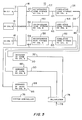
- Fig. 5 is a functional block diagram of a first embodiment of an environment noise analyzer of an EAS system in accordance with the invention.
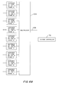
- Fig. 6A and 6B show a functional block diagram of a second embodiment of an environment noise analyzer of an EAS system in accordance with the invention.
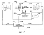
- Fig. 7 shows a functional block diagram of a first embodiment of an EAS system in accordance with the invention.
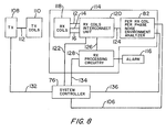
- Fig. 8 shows a functional block diagram of a second embodiment of an EAS system in accordance with the invention.
- Figs. 9A and 9B show a flow chart of a receiving coil interconnect routine implemented by a microprocessor of a system controller for the Fig. 7 EAS system.
- Figs. 10A and 10B show a flow chart of a receiving coil interconnect routine implemented by a microprocessor of a system controller for the Fig. 8 EAS system.
- Fig. 11 depicts a first embodiment of an electronic crosspoint switch for evaluation of standard or Figure-8 configuration coil interconnections.
- Fig. 12 depicts a second embodiment of an electronic crosspoint switch for concurrent evaluation of standard configuration coil interconnections and Figure-8 configuration coil interconnections.
- Fig. 1 it depicts a magnetic field configuration between transmitting coils arranged in "standard” configuration, i.e., wherein both transmitting coil pairs are excited, but pairs in separate antenna assemblies oppose each other, and receiving coils are arranged in " Figure-8" configuration. Flux lines are indicated in solid lines for the transmitting coils and in broken lines for the receiving coils.
- the transmitting coils are in Figure-8 configuration and the receiving coils are in standard configuration.
- both the transmitting coils and the receiving coils are in Figure-8 configuration.
- both the transmitting coils and the receiving coils are in standard configuration.
- the best configuration is for both the transmitting coils and the receiving coils to be in standard configuration.
- this provides the highest overall field strength within the system. In many European countries this field strength exceeds the legal limits.
- Operating the transmitting coils in Figure-8 mode provides far field cancellation of the transmit field, so the levels required to meet their regulatory limits are realizable.
- Individually scanning the receiver coils allows the tag to be sensed in more physical orientations and locations in the system than when in the Figure-8 mode.
- the greatest drawback of the standard mode is that all noise can couple into the coils, which leads to generally higher noise averages.
- the Figure-8 receiving coil configuration is preferred for most installations, since they are typically noisy.
- the noise environment is quiet enough to allow receiving coil operation in standard mode, that mode would be preferred over the Figure-8 receiving coil configuration.
- noise environment analyzer 10 is shown in combination with receiving coils RX COIL A, RX COIL B, RX COIL N.
- the analyzer can be expanded for use with any number of receiving coils, as desired.
- the receiving coil output signals are desirably amplified at the coil situs and are furnished over lines 12, 14 and 16 to scanner 18.
- the scanner looks sequentially at lines 12, 14 and 16 and on looking at each line multiplexes that line with its counterpart one of scanner output lines.
- scanner 18 connects line 12 to line 20, whereby the noise environment of RX COIL A is conveyed to instantaneous noise storage A 22.
- the content of storage 22 is furnished over line 24 to cumulative store A 26, whereby the historical record of noise for RX COIL A is compiled and is available on lines 28 noise averager A 30, which outputs average noise for coil A on line 32.
- scanner 18 Taking the scan of RX COIL B, scanner 18 connects line 14 to line 38, whereby the noise environment of RX COIL B is conveyed to instantaneous noise storage B 40.
- the content of storage 40 is furnished over line 42 to cumulative store B 44, whereby the historical record of noise for RX COIL B is compiled and is available on lines 46 for noise averager B 48, which outputs average noise for coil B on line 50.
- scanner 18 Taking the scan of RX COIL N, scanner 18 connects line 16 to line 56, whereby the noise environment of RX COIL N is conveyed to instantaneous noise storage N 58.
- the content of storage 58 is furnished over line 60 to cumulative store N 62, whereby the historical record of noise for RX COIL N is compiled and is available on lines 64 for noise averager N 66, which outputs average noise for coil C on line 68.
- Lines 32, 50 and 68 provide inputs to multiplexer 74, the operation of which is controlled by system controller 76.
- the multiplexer output is provided on line 78.
- the multiplexer output is furnished to a receiver variable gain amplifier under control of a system controller such that, as returns from RX COIL A are being processed, the gain of the receiver amplifier is set correspondingly with the average noise A.
- the system is likewise operated by the controller to maximize receiver sensitivity for RX COIL B and RX COIL N while the receiver is processing returns respectively from these receiving coils.
- the output of multiplexer 74 is routed to system controller 76 over line 78 in the first system embodiment of Fig. 7, which is below discussed following consideration of Figs. 6A-6B.
- noise environment analyzer 82 is shown in combination with receiving coils RX COIL A, RX COIL B, RX COIL N.
- analyzer 10 of Fig. 5 one channel for average noise computation is provided for each participating receiving coil
- analyzer 82 three channels are provided for each participating coil and output noise averages are provided per coil per phase.
- Scanner 84 functions as did scanner 18, but is expanded to scan the receiving coils for each of phases A, B and C of the power mains.
- the participating channels each of which is configured correspondingly with those of Fig. 1, are noted by reference numerals 86 through 102.
- Channel 86 analyzes returns from RX COIL A during phase A
- channel 88 analyzes returns from RX COIL A during phase B
- channel 90 analyzes returns from RX COIL A during phase C.
- Channels 92, 94 and 96 perform likewise for RX COIL B and channels 98, 100 and 102 perform likewise for RX COIL N.
- Multiplexer 104 receives the noise averages from each channel under timing control from system controller 76.
- the multiplexer output is provided on line 106 and is routed to system controller 76 over line 106, in the second system embodiment of Fig. 8,. which is below discussed following consideration of the first system embodiment.
- each coil in the system is treated as a separate detection unit with its own noise environment which is distinct from the noise environments of the other coils in the system.
- the treatment may be on a per coil basis or on a per coil and per phase basis. This allows the system to optimize its performance in coil configuration control.
- the first system embodiment is shown in a functional block diagram and includes transmitter (TX) 108 which drives transmitter coils (TX COILS) 110 over lines 112, a receiver 114, a system controller 76 and an alarm 116.
- Receiver 114 includes receiver coils 118 (RX COILS), the outputs of which are furnished over lines 12, 14 and 16 to RX COILS INTERCONNECT UNIT 120.
- Unit 120 is controlled by system controller 76 by signals on lines 122 and furnishes its output signals over line 124 to unit 10 (PER RX COIL NOISE ENVIRONMENT ANALYZER), discussed above, and over lines 126 to tag return processing circuitry 128 (RX PROCESSING CIRCUITRY), which controls alarm 116 over lines 130.
- System controller 76 has connection with transmitter 108, processing circuitry 128 and analyzer 10 respectively over lines 132, 134 and 136.
- Fig. 8 will be seen to show a second system embodiment, which is identical with that of Fig. 7, except for its use of analyzer 82.
- the system of the referenced patent application has an active mode, which is composed of a sequence of transmit and noise phases, as alluded to above. Further details of the active mode are set forth in the application and are not relevant to the subject application, which deals not with the active mode, but with a mode which can stand independently or has use as an addendum mode, e.g., a coil connection optimization mode.
- the microprocessor of system controller 76 implements the flow chart of Figs. 9A and 9B.
- the routine is entered in step S1, PER COIL INTERCONNECT ROUTINE.
- step S2 COIL CONFIGURATION A
- the system arranges the receiving coils in, e.g., standard configuration.
- step S3 SCAN RECEIVING COILS FOR NOISE LEVELS
- step S4 STORE CURRENT NOISE LEVELS WITH PAST NOISE LEVELS, the instantaneous noise level provided at the output of scanner 18 is stored with prior stored noise levels for each coil.
- step S5 OBTAIN AVERAGE OF STORED NOISE LEVELS PER COIL
- step S6 CHANGE COIL CONFIGURATION TO CONFIGURATION B
- the system controller directs RX COILS INTERCONNECT UNIT 120 to interconnect the receiving coils to change the coil configuration, e.g., from the standard configuration used above to the Figure-8 configuration.
- step S7 SCAN RECEIVING COILS FOR NOISE LEVELS
- step S8 STORE CURRENT NOISE LEVELS WITH PAST NOISE LEVELS
- step S9 OBTAIN AVERAGE OF STORED NOISE LEVELS PER COIL
- step S10 OBTAIN AVERAGE OF STORED NOISE LEVELS PER COIL
- step S10 inquiry is answered in the negative (N), and progress is to step S13, MAINTAIN COIL CONFIGURATION A, and the routine ends with step S12, RETURN, and the coil configuration is returned to coil configuration A.
- RETURN can be to the active mode of the EAS system of the referenced application or of any desired EAS system employing a plurality of receiving coils.
- step S10 calls out a "PRESELECTED NOISE LEVEL" for each configuration and that the respective preselected noise levels need differ for standard and Figure-8 coil configurations.
- the noise necessary decreases inherently, based on the cancellation of noise as between the oppositely-phased coils.
- the Figure-8 coil configuration would likely always win the contest. Accordingly, the preselected noise level for comparison purposes is set higher for the Figure-8 coil configuration than for the standard configuration.
- the invention contemplates the connection of the terminals of all participating receiving coils to input terminals of an electronic crosspoint switch and the output terminals of the crosspoint switch to lines 124 of Fig. 7.
- System controller 76 accordingly provides input to the crosspoint switch to cause the same to effect the diverse coil configurations as called for by the routine of Figs. 9A and 9B.
- the invention contemplates a routine having steps S1 through S5 of Fig. 9A, a step of comparing the noise level of the coil configuration A with the preselected noise level and simply not changing coil configuration if the noise of coil configuration A compares favorably with the preselected noise level.
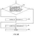
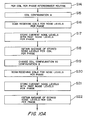
- the microprocessor of system controller 76 implements the flow chart of Figs. 10A and 10B.
- the routine is entered in step S14, PER COIL PER PHASE INTERCONNECT ROUTINE.
- step S15 COIL CONFIGURATION A
- the system arranges the receiving coils in, e.g., standard configuration.
- step S16 SCAN RECEIVING COILS FOR NOISE LEVELS PER PHASE, operation of analyzer 82 of Figs 6A-6B commences.
- step S17 STORE CURRENT NOISE LEVELS WITH PAST NOISE LEVELS PER PHASE, the instantaneous noise level provided at the output of scanner 84 is stored with prior stored noise levels for each coil per phase.
- step S18 OBTAIN AVERAGE OF STORED NOISE LEVELS PER COIL PER PHASE
- step S19 CHANGE COIL CONFIGURATION TO CONFIGURATION B, whereupon the system controller directs RX COILS INTERCONNECT UNIT 120 to interconnect the receiving coils to change the coil configuration, e.g., from the standard configuration used above to the Figure-8 configuration.
- step S20 SCAN RECEIVING COILS FOR NOISE LEVELS PER PHASE, step S21, STORE CURRENT NOISE LEVELS WITH PAST NOISE LEVELS PER PHASE, step S22, OBTAIN AVERAGE OF STORED NOISE LEVELS PER COIL PER PHASE, and step S23, ? RATIO OF AVERAGE NOISE FOR COIL CONFIGURATION B PER PHASE TO PRESELECTED NOISE LEVEL > RATIO OF AVERAGE NOISE RATIO FOR COIL CONFIGURATION A PER PHASE TO PRESELECTED NOISE LEVEL.
- the above comments on different preselected noise levels for the respective different coil configurations applies also to step S23.
- step S23 inquiry is effectively made as to whether system operation can be enhanced by changing coil interconnection configuration. If the inquiry is answered in the affirmative (Y), step S24 is practiced, CHANGE TO COIL CONFIGURATION B FOR THIS PHASE, and the routine ends with step S25, RETURN, and the coil configuration left at its B coil configuration.
- step S23 inquiry is answered in the negative (N)
- step S26 MAINTAIN COIL CONFIGURATION A FOR THIS PHASE
- step S25 RETURN
- step S25 RETURN
- the invention contemplates a routine having steps S1 through S5 of Fig. 10A, a step of comparing the noise level of the coil configuration A per phase with the preselected noise level and simply not changing coil configuration if the noise of coil configuration A per phase compares favorably with the preselected noise level.
- FIG. 11 An electronic crosspoint switch 138 for use in implementing the routines of Figs. 9A, 9B and 10A, 10B is shown in Fig. 11.
- a eight-by-eight switch has eight horizontal conductors and eight vertical conductors. The intersections of the horizontal conductors with the vertical conductors are nodes at which connections may be made. Each node provides a wide bandwidth analog connector for passing signals. Each matrix connection can therefore serve as either an input or output bus. As configured in Fig. 11, the two rightmost vertical conductors provide the switch outputs. All other conductors can be connected individually to participating receiving coils.
- Fig. 11 The basic arrangement of Fig. 11 is capable of connecting coils in the standard configuration, i.e., to connect a single input (coil) to each output and to measure signal levels. Per microprocessor control of active (connected) nodes, progress is to make further pairs of nodes active, and to further measure signal levels, etc.
- coil 140 may be the top coil of the first pedestal, coil 142 the bottom coil of the first pedestal, coil 144 the top coil of the second pedestal and coil 146 the bottom coil of the second pedestal.
- Fig. 11 The open circles in Fig. 11 indicate an active node condition of switch 138 in which coil 140 and coil 144 are under examination, being connected to the switch output conductors.
- Crosspoint switch 148 of Fig. 12 has facility for examining receiving coils in both standard and Figure-8 configurations.
- Coils 140, 142, 144 and 146 are connected directly to switch conductors and are further connected to inverters 150, 152, 154 and 156 and the inverter outputs are connected to switch conductors.
- the switch accordingly has available to it both normal and inverted signals from each coil.
- Creating Figure-8 configurations with switch 148 is effected by connecting any two signals of opposing phase, i.e., a normal signal and an inverted signal to a single output bus. Doing so will effectively null portions of the input signal that are mirrored in the two inputs.
- switch 148 allows further for the connection and monitoring of both standard inputs and Figure-8 inputs simultaneously and leads to a third embodiment of the invention, now discussed.
- the invention will be seen to provide, in combination, in an electrical article surveillance system, a plurality of receiving coils, a noise environment analyzer for determining the noise environment individual to each of the receiving coils and a receiver coil interconnecting unit for variably interconnecting the receiving coils responsively to noise environment determinations of the noise environment analyzer.
- the noise environment analyzer includes scanning circuitry for individually connecting the receiving coils thereto and has separate noise analysis channels respectively for each receiving coil.
- the noise environment analyzer further includes in each channel thereof first circuitry for individual storing of signals received by the receiving coils, second circuitry for cumulative storage of signals stored by the first circuitry, and third circuitry for averaging the signals stored by the second circuitry.
- the noise environmental analyzer further includes multiplexer circuitry for receiving the output signals of the third circuitry and for generating output signals selectively indicative of the third circuitry output signals.
- the system transmitter may be powered from a multi-phase power source.
- the noise environment analyzer further includes separate noise analysis channels respectively for each the receiving coil and for each phase of the multi-phase power source means.
- the noise analysis channels are arranged in groups corresponding in number to the number of receiving coils and wherein each noise analysis channel group comprises channels in number corresponding to the number of phases of the multi-phase power source.
- Noise analysis and coil configuration change can be practiced concurrently with EAS system operation or may be practiced during periods in which the EAS system is rendered inactive.
Landscapes
- Engineering & Computer Science (AREA)
- Physics & Mathematics (AREA)
- Automation & Control Theory (AREA)
- Computer Security & Cryptography (AREA)
- Electromagnetism (AREA)
- General Physics & Mathematics (AREA)
- Signal Processing (AREA)
- Geophysics And Detection Of Objects (AREA)
- Burglar Alarm Systems (AREA)
Applications Claiming Priority (2)
| Application Number | Priority Date | Filing Date | Title |
|---|---|---|---|
| US313848 | 1994-09-28 | ||
| US08/313,848 US5627516A (en) | 1994-09-28 | 1994-09-28 | Electronic article surveillance input configuration control system employing expert system techniques for dynamic optimization |
Publications (3)
| Publication Number | Publication Date |
|---|---|
| EP0704829A2 true EP0704829A2 (de) | 1996-04-03 |
| EP0704829A3 EP0704829A3 (de) | 1997-09-10 |
| EP0704829B1 EP0704829B1 (de) | 2002-09-25 |
Family
ID=23217402
Family Applications (1)
| Application Number | Title | Priority Date | Filing Date |
|---|---|---|---|
| EP95111032A Expired - Lifetime EP0704829B1 (de) | 1994-09-28 | 1995-07-14 | System zur Empfängereingangssteuerung für ein elektronisches Warenüberwachungssystem, das zur dynamischen Optimierung ein Expertensystem verwendet |
Country Status (7)
| Country | Link |
|---|---|
| US (1) | US5627516A (de) |
| EP (1) | EP0704829B1 (de) |
| JP (1) | JPH08125574A (de) |
| AU (1) | AU687607B2 (de) |
| BR (1) | BR9504190A (de) |
| CA (1) | CA2153097C (de) |
| DE (1) | DE69528332T2 (de) |
Cited By (4)
| Publication number | Priority date | Publication date | Assignee | Title |
|---|---|---|---|---|
| EP0844596A2 (de) * | 1996-11-20 | 1998-05-27 | Meto International GmbH | Vorrichtung zur Überwachung eines elektronischen Sicherungselementes in einer Abfragezone |
| DE19650050A1 (de) * | 1996-12-03 | 1998-06-04 | Meto International Gmbh | Vorrichtung zur Überwachung von elektronischen Sicherungselementen |
| DE19722078A1 (de) * | 1997-05-27 | 1998-12-03 | Meto International Gmbh | System zur Überwachung von elektromagnetisch gesicherten Artikeln in mehreren Überwachungszonen |
| CN107609440A (zh) * | 2017-08-31 | 2018-01-19 | 成都威图芯晟科技有限公司 | 一种商品电子检测器的检测方法 |
Families Citing this family (11)
| Publication number | Priority date | Publication date | Assignee | Title |
|---|---|---|---|---|
| US5737241A (en) * | 1995-11-02 | 1998-04-07 | Sensormatic Electronics Corporation | User management interface for EAS system |
| EP0892969A4 (de) * | 1996-04-10 | 2000-12-06 | Sentry Technology Corp | Elektronisches warenüberwachungssystem |
| US5909178A (en) * | 1997-11-28 | 1999-06-01 | Sensormatic Electronics Corporation | Signal detection in high noise environments |
| US6836216B2 (en) * | 2002-05-09 | 2004-12-28 | Electronic Article Surveillance Technologies, Ltd. | Electronic article surveillance system |
| US7518532B2 (en) * | 2005-05-26 | 2009-04-14 | Tc License Ltd. | Intermodulation mitigation technique in an RFID system |
| US8339264B2 (en) * | 2008-02-22 | 2012-12-25 | Xiao Hui Yang | Control unit for an EAS system |
| US8450997B2 (en) * | 2009-04-28 | 2013-05-28 | Brown University | Electromagnetic position and orientation sensing system |
| DE102011014317B4 (de) * | 2011-03-18 | 2021-07-29 | Robert Bosch Gmbh | Sensorüberwachung einer Positionsmessvorrichtung mittels Wärmerauschen |
| WO2014144803A1 (en) | 2013-03-15 | 2014-09-18 | Tyco Fore & Security Gmbh | Method to drive an antenna coil maintaining limited power source output |
| US9576455B2 (en) * | 2014-06-10 | 2017-02-21 | Wg Security Products | Cloud EAS synchronization and firmware update |
| US9595177B2 (en) | 2014-12-14 | 2017-03-14 | Wg Security Products, Inc. | Noise compensating EAS antenna system |
Family Cites Families (11)
| Publication number | Priority date | Publication date | Assignee | Title |
|---|---|---|---|---|
| US4394645A (en) * | 1981-09-10 | 1983-07-19 | Sensormatic Electronics Corporation | Electrical surveillance apparatus with moveable antenna elements |
| CA1234892A (en) * | 1984-02-16 | 1988-04-05 | Pierre Taillefer | Security tag detection system |
| US4720701A (en) * | 1986-01-02 | 1988-01-19 | Lichtblau G J | System with enhanced signal detection and discrimination with saturable magnetic marker |
| US4769631A (en) * | 1986-06-30 | 1988-09-06 | Sensormatic Electronics Corporation | Method, system and apparatus for magnetic surveillance of articles |
| US4906973A (en) * | 1988-04-29 | 1990-03-06 | White's Electronics, Inc. | Walk-through metal detector |
| US4994939A (en) * | 1989-11-15 | 1991-02-19 | Minnesota Mining And Manufacturing Company | Universal lattice for magnetic-electronic article surveillance system |
| US5023598A (en) * | 1990-01-02 | 1991-06-11 | Pitney Bowes Inc. | Digital signal processor for electronic article gates |
| US5397986A (en) * | 1991-11-01 | 1995-03-14 | Federal Labs Systems Lp | Metal detector system having multiple, adjustable transmitter and receiver antennas |
| EP0561062A1 (de) * | 1992-03-17 | 1993-09-22 | Moisei Samuel Granovsky | Verfahren und elektromagnetisches Sicherheitssystem, um geschützte Gegenstände in einem Überwachungsbereich zu entdecken |
| US5349332A (en) * | 1992-10-13 | 1994-09-20 | Sensormatic Electronics Corportion | EAS system with requency hopping |
| US5495229A (en) * | 1994-09-28 | 1996-02-27 | Sensormatic Electronics Corporation | Pulsed electronic article surveillance device employing expert system techniques for dynamic optimization |
-
1994
- 1994-09-28 US US08/313,848 patent/US5627516A/en not_active Expired - Lifetime
-
1995
- 1995-06-30 CA CA002153097A patent/CA2153097C/en not_active Expired - Fee Related
- 1995-07-14 EP EP95111032A patent/EP0704829B1/de not_active Expired - Lifetime
- 1995-07-14 DE DE69528332T patent/DE69528332T2/de not_active Expired - Fee Related
- 1995-09-21 AU AU32805/95A patent/AU687607B2/en not_active Ceased
- 1995-09-27 BR BR9504190A patent/BR9504190A/pt not_active Application Discontinuation
- 1995-09-28 JP JP7274818A patent/JPH08125574A/ja active Pending
Non-Patent Citations (1)
| Title |
|---|
| None |
Cited By (6)
| Publication number | Priority date | Publication date | Assignee | Title |
|---|---|---|---|---|
| EP0844596A2 (de) * | 1996-11-20 | 1998-05-27 | Meto International GmbH | Vorrichtung zur Überwachung eines elektronischen Sicherungselementes in einer Abfragezone |
| EP0844596A3 (de) * | 1996-11-20 | 1999-12-08 | Meto International GmbH | Vorrichtung zur Überwachung eines elektronischen Sicherungselementes in einer Abfragezone |
| DE19650050A1 (de) * | 1996-12-03 | 1998-06-04 | Meto International Gmbh | Vorrichtung zur Überwachung von elektronischen Sicherungselementen |
| DE19722078A1 (de) * | 1997-05-27 | 1998-12-03 | Meto International Gmbh | System zur Überwachung von elektromagnetisch gesicherten Artikeln in mehreren Überwachungszonen |
| CN107609440A (zh) * | 2017-08-31 | 2018-01-19 | 成都威图芯晟科技有限公司 | 一种商品电子检测器的检测方法 |
| CN107609440B (zh) * | 2017-08-31 | 2020-12-08 | 成都威图芯晟科技有限公司 | 一种商品电子检测器的检测方法 |
Also Published As
| Publication number | Publication date |
|---|---|
| CA2153097C (en) | 2004-08-24 |
| BR9504190A (pt) | 1996-08-06 |
| AU3280595A (en) | 1996-04-18 |
| JPH08125574A (ja) | 1996-05-17 |
| EP0704829A3 (de) | 1997-09-10 |
| CA2153097A1 (en) | 1996-03-29 |
| AU687607B2 (en) | 1998-02-26 |
| DE69528332T2 (de) | 2003-01-23 |
| DE69528332D1 (de) | 2002-10-31 |
| EP0704829B1 (de) | 2002-09-25 |
| US5627516A (en) | 1997-05-06 |
Similar Documents
| Publication | Publication Date | Title |
|---|---|---|
| US5495229A (en) | Pulsed electronic article surveillance device employing expert system techniques for dynamic optimization | |
| US5627516A (en) | Electronic article surveillance input configuration control system employing expert system techniques for dynamic optimization | |
| US5955950A (en) | Low noise signal generator for use with an RFID system | |
| US5353011A (en) | Electronic article security system with digital signal processing and increased detection range | |
| EP0316963B1 (de) | Mit mehreren Frequenzen arbeitendes Ladendiebstahl-Sicherungssystem | |
| EP0696783B1 (de) | Warenüberwachungssystem mit Etikettendeaktivierungskapazität | |
| CA1234892A (en) | Security tag detection system | |
| EP2524360B1 (de) | Verfahren und system für empfänger-nulling mit kohärenten übertragungssignalen | |
| JPS5854440B2 (ja) | 保護された品物が探索ゾ−ンを経て不当搬出されることを検出するための電子式盗難検知装置 | |
| AU606295B2 (en) | False alarm minimization and direction determination methods | |
| EP0646266B1 (de) | Verfahren und vorrichtung zur diebstahldetektion durch digitalsignalverarbeitung. | |
| CN1096049C (zh) | 具有梳状滤波和误报警抑制的电子物品监视系统 | |
| JP4445672B2 (ja) | 低パワー共振タグ検出用高周波識別システム | |
| EP0207020A1 (de) | Anordnung für Alarmsysteme insbesondere zur Verhinderung von Diebstahl in Warenhäusern | |
| AU716217B2 (en) | Pulsed electronic article surveillance device employing expert system techniques for dynamic optimization | |
| Stathaki | Blind volterra signal modeling | |
| EP0608039A1 (de) | Ladendiebstahldetektierungssystem, insbesondere geeignet für den Gebrauch in Supermärkten, und ein Ladenentwurf mit solchem System | |
| EP1687785B1 (de) | Artikelsicherungssystem | |
| JP2000252890A (ja) | データ通信装置 | |
| MXPA01000883A (en) | Rfid system for detecting low power resonant tags | |
| JP2000252889A (ja) | データ通信装置 |
Legal Events
| Date | Code | Title | Description |
|---|---|---|---|
| PUAI | Public reference made under article 153(3) epc to a published international application that has entered the european phase |
Free format text: ORIGINAL CODE: 0009012 |
|
| AK | Designated contracting states |
Kind code of ref document: A2 Designated state(s): DE FR GB SE |
|
| PUAL | Search report despatched |
Free format text: ORIGINAL CODE: 0009013 |
|
| AK | Designated contracting states |
Kind code of ref document: A3 Designated state(s): DE FR GB SE |
|
| 17P | Request for examination filed |
Effective date: 19980310 |
|
| 17Q | First examination report despatched |
Effective date: 20000117 |
|
| GRAG | Despatch of communication of intention to grant |
Free format text: ORIGINAL CODE: EPIDOS AGRA |
|
| GRAG | Despatch of communication of intention to grant |
Free format text: ORIGINAL CODE: EPIDOS AGRA |
|
| GRAG | Despatch of communication of intention to grant |
Free format text: ORIGINAL CODE: EPIDOS AGRA |
|
| GRAG | Despatch of communication of intention to grant |
Free format text: ORIGINAL CODE: EPIDOS AGRA |
|
| GRAH | Despatch of communication of intention to grant a patent |
Free format text: ORIGINAL CODE: EPIDOS IGRA |
|
| RAP1 | Party data changed (applicant data changed or rights of an application transferred) |
Owner name: SENSORMATIC ELECTRONICS CORPORATION |
|
| GRAH | Despatch of communication of intention to grant a patent |
Free format text: ORIGINAL CODE: EPIDOS IGRA |
|
| GRAA | (expected) grant |
Free format text: ORIGINAL CODE: 0009210 |
|
| AK | Designated contracting states |
Kind code of ref document: B1 Designated state(s): DE FR GB SE |
|
| REG | Reference to a national code |
Ref country code: GB Ref legal event code: FG4D |
|
| REF | Corresponds to: |
Ref document number: 69528332 Country of ref document: DE Date of ref document: 20021031 |
|
| PG25 | Lapsed in a contracting state [announced via postgrant information from national office to epo] |
Ref country code: SE Free format text: LAPSE BECAUSE OF FAILURE TO SUBMIT A TRANSLATION OF THE DESCRIPTION OR TO PAY THE FEE WITHIN THE PRESCRIBED TIME-LIMIT Effective date: 20021225 |
|
| PG25 | Lapsed in a contracting state [announced via postgrant information from national office to epo] |
Ref country code: GB Free format text: LAPSE BECAUSE OF NON-PAYMENT OF DUE FEES Effective date: 20030714 |
|
| PLBE | No opposition filed within time limit |
Free format text: ORIGINAL CODE: 0009261 |
|
| STAA | Information on the status of an ep patent application or granted ep patent |
Free format text: STATUS: NO OPPOSITION FILED WITHIN TIME LIMIT |
|
| 26N | No opposition filed |
Effective date: 20030626 |
|
| GBPC | Gb: european patent ceased through non-payment of renewal fee |
Effective date: 20030714 |
|
| REG | Reference to a national code |
Ref country code: FR Ref legal event code: CA |
|
| PGFP | Annual fee paid to national office [announced via postgrant information from national office to epo] |
Ref country code: DE Payment date: 20070831 Year of fee payment: 13 |
|
| PG25 | Lapsed in a contracting state [announced via postgrant information from national office to epo] |
Ref country code: DE Free format text: LAPSE BECAUSE OF NON-PAYMENT OF DUE FEES Effective date: 20090203 |
|
| REG | Reference to a national code |
Ref country code: FR Ref legal event code: TP Owner name: SENSORMATIC ELECTRONICS, LLC, US Effective date: 20110913 |
|
| PGFP | Annual fee paid to national office [announced via postgrant information from national office to epo] |
Ref country code: FR Payment date: 20110805 Year of fee payment: 17 |
|
| REG | Reference to a national code |
Ref country code: FR Ref legal event code: ST Effective date: 20130329 |
|
| PG25 | Lapsed in a contracting state [announced via postgrant information from national office to epo] |
Ref country code: FR Free format text: LAPSE BECAUSE OF NON-PAYMENT OF DUE FEES Effective date: 20120731 |