EP0704819B1 - Dispositif et procédé de test mécanique de cartes de circuit(s) intégré(s) - Google Patents
Dispositif et procédé de test mécanique de cartes de circuit(s) intégré(s) Download PDFInfo
- Publication number
- EP0704819B1 EP0704819B1 EP19950402178 EP95402178A EP0704819B1 EP 0704819 B1 EP0704819 B1 EP 0704819B1 EP 19950402178 EP19950402178 EP 19950402178 EP 95402178 A EP95402178 A EP 95402178A EP 0704819 B1 EP0704819 B1 EP 0704819B1
- Authority
- EP
- European Patent Office
- Prior art keywords
- card
- roller
- press roller
- test
- support
- Prior art date
- Legal status (The legal status is an assumption and is not a legal conclusion. Google has not performed a legal analysis and makes no representation as to the accuracy of the status listed.)
- Expired - Lifetime
Links
Images

Classifications
-
- G—PHYSICS
- G06—COMPUTING OR CALCULATING; COUNTING
- G06K—GRAPHICAL DATA READING; PRESENTATION OF DATA; RECORD CARRIERS; HANDLING RECORD CARRIERS
- G06K19/00—Record carriers for use with machines and with at least a part designed to carry digital markings
- G06K19/06—Record carriers for use with machines and with at least a part designed to carry digital markings characterised by the kind of the digital marking, e.g. shape, nature, code
- G06K19/067—Record carriers with conductive marks, printed circuits or semiconductor circuit elements, e.g. credit or identity cards also with resonating or responding marks without active components
- G06K19/07—Record carriers with conductive marks, printed circuits or semiconductor circuit elements, e.g. credit or identity cards also with resonating or responding marks without active components with integrated circuit chips
-
- G—PHYSICS
- G01—MEASURING; TESTING
- G01N—INVESTIGATING OR ANALYSING MATERIALS BY DETERMINING THEIR CHEMICAL OR PHYSICAL PROPERTIES
- G01N3/00—Investigating strength properties of solid materials by application of mechanical stress
- G01N3/20—Investigating strength properties of solid materials by application of mechanical stress by applying steady bending forces
Definitions
- the present invention relates to a device for mechanical test for a card, such as a credit card or an access card for example, comprising one or more integrated circuits to each of which is associated, or not, a electrical contact area on the card.
- the invention also relates to a method of setting using such a device.
- the devices designed and used to test, evaluate, control the quality and reliability of microcircuit cards in the field of resistance to fatigue or mechanical or physical stress are the bending and torsion devices defined by standards ISO 7816 and ISO / IEC 10373. These devices have made it possible to guarantee a minimum level of quality until then.
- test devices indicated above do not reveal practically no more failure today, after tests, while there are still some in the field, even if there are proportionately fewer compared to the cards of older technologies. This remains true even if we increases the level of constraints brought by these devices test, by an increased number of bends or twists, or an increase in the deflection or the angle of torsion. These tests therefore no longer highlight the failures of new integrated circuit (s) cards, especially with contacts, actually observed in the field, this which indicates an increasingly poor correlation between the test and actual use.
- the object of the invention is to develop a method mechanical test card particularly suitable for testing of integrated circuit (s) cards, with or without contacts contacts, and a device for implementing this process.
- the device described in the first paragraph of this description includes the first means of support against which at least one card is applied, second positioning and sliding means for print an alternating back and forth movement on said card substantially in its plane and at least one pressure roller to apply with a predetermined force, by rolling without sliding, said card against said first means support, said first and second means and said pressure roller being arranged between them so that the roller rolls on the location of at least one circuit area integrated of the card with each movement of alternating passage of the map.
- the invention makes it possible to quickly test a card, in less than 2 mm; it also provides the correlation above for each type of application for which each card is specialized, regardless of technology used to make the card, and without it is marked by the test device at the end of the test.
- test according to the invention can be supplemented by standard standardized tests of torsion or bending the card.
- Figure 1 shows a first mode of embodiment of the device according to the invention, FIG. 1A in side view and Figure 1B in top view with tearing.
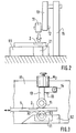
- Figure 2 is a partial rear view of a second embodiment.
- Figure 3 is a side view with cutaway of a third embodiment.
- Figure 4 is a side view with cutaway of a fourth embodiment.
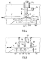
- Figure 5 is a side view with cutaway of a fifth embodiment which combines the second, third and fourth embodiments of the invention.
- FIG. 1A there is shown so schematic a mechanical card testing device as well an integrated circuit card 1 under test comprising an integrated circuit and contact area 2, in which finds an integrated circuit (memory or microprocessor not visible in the drawing) connected by conductive wires or conductive tracks at contact pads 3 (FIG. 1B).
- the test device is itself constituted by a system connecting rod-crank (connecting rod 4 and crank 5) driven so known by a motor 6, preferably an electric motor.
- a motor 6 preferably an electric motor.
- a base 8 provided with a beveled end for the introduction cards to be tested, constitutes the first means of support of card 1.
- This base consists of a block of material having a flat face 9 designed to support sliding with a predetermined force each card to be tested and it's for example made of Teflon.
- the axis 12 is itself secured to a bent arm 13 mounted at pivoting on an axis 14 supported by a partition 15.
- the arm 16 has at its free end a rod 17 which is perpendicular thereto and on which can slide three masses M0, M1 and M2.
- Elements 4 to 7 constitute second means positioning and sliding that print to the card a reciprocating back and forth movement substantially in a plane (preferably horizontal plane) and in such a way that the roller remains permanently in contact with the card.
- the roller 11 which is made of a hard material or semi-hard designed not to mark the card at the end of the test, the support 8 and the rod-crank system 4 to 7, are arranged between them so that the roller 11 rolls over all the area of the integrated circuit and contacts 2 at each alternating pass movement of the card.
- the width of the roll is slightly less than the diameter of zone 2, and for example equal to 5 mm.
- the force to be applied by the roller 11 differs depending on the application planned for the card to be tested. For a standard bank card application, this force is from 7N to 9N and for an access control card, around 14N to 16N.
- the number of press roller passages on the zone 2 varies according to the simulated duration of use. For a duration of use of one year, for example, the number of round trips is around 50, at a frequency about 0.5 Hz.
- the embodiment of the test device shown in Figure 2 is characterized in that the block of support material, referenced 81, comprises, facing the pressure roller 11, a slot 21 whose width is substantially equal to the diameter of zone 2 of the map, and about 1.5 times the width of the roll 11, for example 8 mm for a width of the roll of 5 mm.
- the card still slides on the support 81, except at the base of the roller 11 where a cantilever effect is generated.
- the block of support material 82 comprises a housing (recess) 31 to receive free rotation around an axis 32 a support roller 33, located opposite the pressure roller 11.
- the effect of the test obtained with this third device is comparable to that resulting from the first device of FIG. 1.
- the absence of friction here facilitates the back and forth movements of the card during the test.
- the roller 33 of FIG. 3 is replaced by a pair of support rollers 42 and 43, arranged in a recess 41 of the block of support material 83, on either side of the line plumb 44 of the pressure roller 11.
- a cantilever effect is thus obtained according to the direction of movement of the card, either the direction perpendicular to that of the second mode of embodiment of Figure 2 described above.
- the embodiment of Figure 5 combines the second, third and fourth embodiments of Figures 2, 3 and 4 respectively.
- an axis 51 supported by the partition 15 pivotally supports three bent axes 52, 53, 54, each provided with a pressure roller 55, 56, 57 these three pressure rollers apply generally different forces, F 1, F 2, F 3, against the card 1.
- the block of support material 84 comprises a housing 58, provided with three rollers, 59 and 61, and 62. At the rear part of the support block 84, a slot 63 allows the implementation of the second embodiment.
- the constraints imposed on the contact area 2 of the card are higher than for the first embodiments previously described; the number of alternating passages of the card 1 under the pressure rollers can be reduced to less than 50 and the duration of the test can therefore be reduced, which is moreover more complete than for the other embodiments.
- the pressure rollers or the support rollers can be constituted by ball bearings, for example made of steel.
- the card could be pinched laterally instead of being at the end.
- the clamp 7 must be adapted to enter a multiplicity of cards in battery, the block of carrier material must be widened accordingly and the number of rolls or slots multiplied by the number of cards to test.
- the pressure roller (s) on the board when the introduction of the latter under this (these) roller (s)
- the force to be applied on the axis of pressure rollers could be obtained otherwise than by gravity, by means of springs calibrated in particular, so as to allow alternating movement of the card according to any desired orientation.
- test device of the invention can be coupled with an electric card reader, to be disposed of the free end (on the right in the figures), which allows check in real time, i.e. on each pass alternating of the card, the good working condition of this last and trigger an alarm, or stop the test, as soon as that a fault appears.
Landscapes
- Physics & Mathematics (AREA)
- Engineering & Computer Science (AREA)
- General Physics & Mathematics (AREA)
- Health & Medical Sciences (AREA)
- Microelectronics & Electronic Packaging (AREA)
- Theoretical Computer Science (AREA)
- Computer Hardware Design (AREA)
- Life Sciences & Earth Sciences (AREA)
- Chemical & Material Sciences (AREA)
- Analytical Chemistry (AREA)
- Biochemistry (AREA)
- General Health & Medical Sciences (AREA)
- Immunology (AREA)
- Pathology (AREA)
- Tests Of Electronic Circuits (AREA)
Description
- l'insertion de chaque carte entre au moins un rouleau presseur et des moyens de support,
- l'application d'une force de pincement de la carte, comprise entre 7N et 15N, entre ledit (lesdits) rouleau(x) presseur(s) et lesdits moyens de support,
- la mise en mouvement de la carte selon un mouvement alternatif de va-et-vient sensiblement dans son plan dans un sens perpendiculaire aux génératrices du(des) rouleau(x) presseur(s) et de telle sorte que ce(ces) dernier(s) roule(nt) sur l'emplacement d'une zone de circuit intégré de la carte à chaque mouvement de passage alternant de la carte.
Claims (11)
- Dispositif de test mécanique de cartes, caractérisé en ce que, étant conçu pour tester des cartes à circuit(s) intégré(s) à contacts, il comporte des premiers moyens de support (8) contre lesquels est appliquée au moins une carte (1), des deuxièmes moyens de positionnement et de coulissement (4-7) pour imprimer à ladite carte un mouvement alternatif de va-et-vient sensiblement dans son plan et au moins un rouleau presseur (11) pour appliquer avec une force prédéterminée, par roulement sans glissement, ladite carte contre lesdits premiers moyens de support, lesdits premiers et deuxièmes moyens et ledit rouleau presseur étant agencés entre eux de telle sorte que le rouleau roule sur l'emplacement d'au moins une zone de circuit intégré (2), avec ou sans contacts, de la carte (1) à chaque mouvement de passage alternant de la carte.
- Dispositif de test selon la revendication 1, caractérisé en ce que la largeur dudit rouleau (11) est légèrement inférieure au diamètre de la zone de circuit intégré (2) de la carte (1).
- Dispositif de test selon la revendication 1 ou 2, caractérisé en ce qu'il est orienté pour tester chaque carte (1) horizontalement, et que l'axe dudit rouleau (11) est situé au-dessus de la carte et supporte un lest prédéterminé selon le type d'application envisagé pour la carte à tester.
- Dispositif de test selon l'une des revendications 1 à 3, caractérisé en ce que lesdits premiers moyens de support (8) sont constitués par un bloc de matériau présentant une face plane conçue pour supporter à glissement chaque carte à tester.
- Dispositif de test selon la revendication 4, caractérisé en ce que ledit bloc de matériau comporte, située en regard dudit rouleau presseur, une fente (21) dont la largeur est sensiblement égale au diamètre de ladite zone de circuit intégré de la carte.
- Dispositif de test selon l'une des revendications 1 à 3, caractérisé en ce que lesdits premiers moyens de support (8) sont constitués par un rouleau de support (33) situé en regard dudit rouleau presseur (11).
- Dispositif de test selon l'une des revendications 1 à 3, caractérisé en ce que lesdits premiers moyens de support sont constitués par une paire de rouleaux de support (42, 43) disposés de part et d'autre de l'aplomb dudit rouleau presseur (11).
- Dispositif presseur selon l'une des revendications 1 à 3, caractérisé en ce qu'il comporte en outre deux rouleaux presseurs supplémentaires et que lesdits moyens de support sont constitués par un bloc de matériau comportant, en regard d'un premier rouleau presseur, une fente dont la largeur est sensiblement égale au diamètre de ladite zone de circuit intégré (2) de la carte (1), par un rouleau de support situé en regard d'un deuxième rouleau presseur et par une paire de rouleaux de support disposés de part et d'autre de l'aplomb dudit rouleau presseur.
- Dispositif presseur selon l'une des revendications 1 à 8, caractérisé en ce que ladite force prédéterminée appliquée par un rouleau presseur (11) contre une carte (1) est comprise entre 7N et 15N.
- Procédé de test mécanique de cartes, caractérisé en ce que, étant destiné au test de carte à circuit(s) intégré(s), il comporte la succession d'étapes suivantes :l'insertion de chaque carte entre au moins un rouleau presseur et des moyens de support,l'application d'une force de pincement de la carte, comprise entre 7N et 15N, entre ledit (lesdits) rouleau(x) presseur(s) et lesdits moyens de support,la mise en mouvement de la carte selon un mouvement alternatif de va-et-vient sensiblement dans son plan dans un sens perpendiculaire aux génératrices du(des) rouleau(x) presseur(s) et de telle sorte que ce(ces) dernier(s) roule(nt) sur l'emplacement d'une zone de circuit intégré, avec ou sans contacts, de la carte à chaque mouvement de passage alternant de la carte.
- Procédé de test mécanique de cartes selon la revendication 10, caractérisé en ce que pour une durée d'utilisation simulée de la carte égale à un an, le nombre de mouvements de passage alternant de la carte, aller et retour, est compris entre 10 et 60, à une fréquence de l'ordre de 0,5 Hz.
Applications Claiming Priority (2)
| Application Number | Priority Date | Filing Date | Title |
|---|---|---|---|
| FR9411753 | 1994-09-30 | ||
| FR9411753A FR2725290B1 (fr) | 1994-09-30 | 1994-09-30 | Dispositif et procede de test mecanique de cartes a circuit(s) integre(s) |
Publications (2)
| Publication Number | Publication Date |
|---|---|
| EP0704819A1 EP0704819A1 (fr) | 1996-04-03 |
| EP0704819B1 true EP0704819B1 (fr) | 2001-04-11 |
Family
ID=9467483
Family Applications (1)
| Application Number | Title | Priority Date | Filing Date |
|---|---|---|---|
| EP19950402178 Expired - Lifetime EP0704819B1 (fr) | 1994-09-30 | 1995-09-28 | Dispositif et procédé de test mécanique de cartes de circuit(s) intégré(s) |
Country Status (3)
| Country | Link |
|---|---|
| EP (1) | EP0704819B1 (fr) |
| DE (1) | DE69520634T2 (fr) |
| FR (1) | FR2725290B1 (fr) |
Cited By (2)
| Publication number | Priority date | Publication date | Assignee | Title |
|---|---|---|---|---|
| EP1637866A1 (fr) * | 2004-09-21 | 2006-03-22 | VisionCard PersonalisierungsgmbH | Procédé et dispositif pour tester la flexion de cartes |
| EP4675248A1 (fr) | 2024-07-04 | 2026-01-07 | Bundesdruckerei GmbH | Dispositif et procédé de test d'une carte à puce |
Families Citing this family (9)
| Publication number | Priority date | Publication date | Assignee | Title |
|---|---|---|---|---|
| FR2785393B1 (fr) * | 1998-10-28 | 2001-01-19 | Solaic Sa | Appareil de test pour cartes a memoire electronique |
| FR2793033B1 (fr) * | 1999-04-30 | 2001-06-08 | Gemplus Card Int | Procede et dispositif de vieillissement accelere de cartes en matiere plastique du type des cartes a puce |
| US6394346B1 (en) | 1999-10-07 | 2002-05-28 | Cubic Corporation | Contactless smart card high production encoding machine |
| FR2808878B1 (fr) * | 2000-05-11 | 2002-09-06 | Gemplus Card Int | Procede et dispositif de controle de la fiabilite et de la resistance a la fatigue de circuits electroniques conditionnes sous forme de bande |
| DE10222211B4 (de) * | 2002-05-16 | 2015-04-02 | Morpho Cards Gmbh | Verfahren zum Testen des Sprödbruchverhaltens von Chipkarten |
| FR3009617B1 (fr) * | 2013-08-07 | 2019-08-02 | Idemia France | Procede de test de resistance d'une carte a puce et dispositif pour la realisation d'un tel test |
| FR3017712B1 (fr) * | 2014-02-14 | 2016-03-25 | Oberthur Technologies | Procede de mesure de la resistance des attaches reliant une carte a son support et outil pour la mise en oeuvre de ce procede |
| CN106546494B (zh) * | 2016-09-28 | 2023-05-19 | 重庆圣巴巴拉实业有限公司 | 汽车轮毂回转弯曲试验机 |
| CN106338432B (zh) * | 2016-09-28 | 2024-02-20 | 重庆圣巴巴拉实业有限公司 | 转向节刚性固定轮毂回转弯曲试验机轮毂夹紧装置 |
Family Cites Families (2)
| Publication number | Priority date | Publication date | Assignee | Title |
|---|---|---|---|---|
| US4926694A (en) * | 1989-07-28 | 1990-05-22 | The United States Of America As Represented By The United States National Aeronautics And Space Administration | Delamination test apparatus and method |
| US5184517A (en) * | 1991-11-01 | 1993-02-09 | Robert Kelzer | Printed circuit board test fixture and method |
-
1994
- 1994-09-30 FR FR9411753A patent/FR2725290B1/fr not_active Expired - Fee Related
-
1995
- 1995-09-28 DE DE1995620634 patent/DE69520634T2/de not_active Expired - Fee Related
- 1995-09-28 EP EP19950402178 patent/EP0704819B1/fr not_active Expired - Lifetime
Cited By (2)
| Publication number | Priority date | Publication date | Assignee | Title |
|---|---|---|---|---|
| EP1637866A1 (fr) * | 2004-09-21 | 2006-03-22 | VisionCard PersonalisierungsgmbH | Procédé et dispositif pour tester la flexion de cartes |
| EP4675248A1 (fr) | 2024-07-04 | 2026-01-07 | Bundesdruckerei GmbH | Dispositif et procédé de test d'une carte à puce |
Also Published As
| Publication number | Publication date |
|---|---|
| EP0704819A1 (fr) | 1996-04-03 |
| DE69520634D1 (de) | 2001-05-17 |
| FR2725290B1 (fr) | 1996-12-20 |
| DE69520634T2 (de) | 2001-11-29 |
| FR2725290A1 (fr) | 1996-04-05 |
Similar Documents
| Publication | Publication Date | Title |
|---|---|---|
| EP0704819A1 (fr) | Dispositif et procédé de test mécanique de cartes de circuit(s) intégré(s) | |
| EP0316700B1 (fr) | Cadre de contact pour lecteur de carte à puce | |
| CH635706A5 (fr) | Connecteur electrique pour un objet portatif. | |
| EP0518789B1 (fr) | Carte à pointes pour testeur de puces de circuit intégré | |
| FR2766945A1 (fr) | Machine de personnalisation a haute cadence | |
| FR2819315A1 (fr) | Module a broches de contact et dispositif de controle equipe de ce module | |
| FR2535064A1 (fr) | Dispositif de controle automatique de specimens electroniques | |
| EP0873582B1 (fr) | Outil portable pour le sertissage de broches de connexion sur des conducteurs electriques | |
| EP0338900A1 (fr) | Dispositif de mise en contact électrique de conducteurs répartis sur deux éléments et notamment entre ceux d'une carte à mémoire et ceux de son lecteur | |
| FR2775373A1 (fr) | Connecteur et lecteur de carte a puce comportant un tel connecteur | |
| EP0029467B1 (fr) | Appareil électrique comprenant une série de prises de tension et un équipage sélecteur mobile | |
| FR2545214A1 (fr) | Broche electromecanique de conversion de mesure | |
| EP0997740B1 (fr) | Appareil de test pour cartes à mémoire électronique | |
| EP0190527A1 (fr) | Connecteur pour objets portatifs incluant un circuit électrique ou électronique, tels qu'une carte électronique | |
| WO1996013078A1 (fr) | Dispositif de connexion de puissance | |
| FR2790084A1 (fr) | Systeme de mesure de la force appliquee par les contacts elastiques d'un connecteur de lecteur de cartes a puce sur les contacts correspondants d'une carte a puce | |
| EP0109057A2 (fr) | Sélecteur de pièces de monnaie | |
| EP0305324B1 (fr) | Appareil de réglage d'une fixation de sécurité pour ski | |
| WO2000066996A1 (fr) | Procede et dispositif de vieillissement accelere de cartes en matiere plastique du type des cartes a puce | |
| FR3115637A1 (fr) | Connecteur pour la connexion d’une terminaison électrique sur un circuit imprimé, procédés d’assemblage correspondants. | |
| JPS58184558A (ja) | コネクタ圧接検査装置 | |
| CH289512A (fr) | Commutateur électrique à bascule. | |
| FR2588667A1 (fr) | Appareil de mesure de la resistivite d'une couche mince | |
| EP1798695B1 (fr) | Système électronique connecté à un câble électrique à tenue en fatigue de câble améliorée | |
| EP1056035A1 (fr) | Connecteur à atterrissage |
Legal Events
| Date | Code | Title | Description |
|---|---|---|---|
| PUAI | Public reference made under article 153(3) epc to a published international application that has entered the european phase |
Free format text: ORIGINAL CODE: 0009012 |
|
| AK | Designated contracting states |
Kind code of ref document: A1 Designated state(s): DE GB |
|
| 17P | Request for examination filed |
Effective date: 19960930 |
|
| GRAG | Despatch of communication of intention to grant |
Free format text: ORIGINAL CODE: EPIDOS AGRA |
|
| 17Q | First examination report despatched |
Effective date: 20000727 |
|
| GRAG | Despatch of communication of intention to grant |
Free format text: ORIGINAL CODE: EPIDOS AGRA |
|
| GRAH | Despatch of communication of intention to grant a patent |
Free format text: ORIGINAL CODE: EPIDOS IGRA |
|
| GRAH | Despatch of communication of intention to grant a patent |
Free format text: ORIGINAL CODE: EPIDOS IGRA |
|
| GRAA | (expected) grant |
Free format text: ORIGINAL CODE: 0009210 |
|
| AK | Designated contracting states |
Kind code of ref document: B1 Designated state(s): DE GB |
|
| REF | Corresponds to: |
Ref document number: 69520634 Country of ref document: DE Date of ref document: 20010517 |
|
| GBT | Gb: translation of ep patent filed (gb section 77(6)(a)/1977) |
Effective date: 20010628 |
|
| REG | Reference to a national code |
Ref country code: GB Ref legal event code: IF02 |
|
| PLBE | No opposition filed within time limit |
Free format text: ORIGINAL CODE: 0009261 |
|
| STAA | Information on the status of an ep patent application or granted ep patent |
Free format text: STATUS: NO OPPOSITION FILED WITHIN TIME LIMIT |
|
| 26N | No opposition filed | ||
| PGFP | Annual fee paid to national office [announced via postgrant information from national office to epo] |
Ref country code: DE Payment date: 20070829 Year of fee payment: 13 |
|
| PGFP | Annual fee paid to national office [announced via postgrant information from national office to epo] |
Ref country code: GB Payment date: 20070830 Year of fee payment: 13 |
|
| GBPC | Gb: european patent ceased through non-payment of renewal fee |
Effective date: 20080928 |
|
| PG25 | Lapsed in a contracting state [announced via postgrant information from national office to epo] |
Ref country code: DE Free format text: LAPSE BECAUSE OF NON-PAYMENT OF DUE FEES Effective date: 20090401 |
|
| PG25 | Lapsed in a contracting state [announced via postgrant information from national office to epo] |
Ref country code: GB Free format text: LAPSE BECAUSE OF NON-PAYMENT OF DUE FEES Effective date: 20080928 |