EP0704792B1 - Method of managing memory allocation in a printing system - Google Patents
Method of managing memory allocation in a printing system Download PDFInfo
- Publication number
- EP0704792B1 EP0704792B1 EP95306919A EP95306919A EP0704792B1 EP 0704792 B1 EP0704792 B1 EP 0704792B1 EP 95306919 A EP95306919 A EP 95306919A EP 95306919 A EP95306919 A EP 95306919A EP 0704792 B1 EP0704792 B1 EP 0704792B1
- Authority
- EP
- European Patent Office
- Prior art keywords
- block
- blocks
- memory
- image
- image data
- Prior art date
- Legal status (The legal status is an assumption and is not a legal conclusion. Google has not performed a legal analysis and makes no representation as to the accuracy of the status listed.)
- Expired - Lifetime
Links
Images


Classifications
-
- H—ELECTRICITY
- H04—ELECTRIC COMMUNICATION TECHNIQUE
- H04N—PICTORIAL COMMUNICATION, e.g. TELEVISION
- H04N1/00—Scanning, transmission or reproduction of documents or the like, e.g. facsimile transmission; Details thereof
- H04N1/32—Circuits or arrangements for control or supervision between transmitter and receiver or between image input and image output device, e.g. between a still-image camera and its memory or between a still-image camera and a printer device
- H04N1/32502—Circuits or arrangements for control or supervision between transmitter and receiver or between image input and image output device, e.g. between a still-image camera and its memory or between a still-image camera and a printer device in systems having a plurality of input or output devices
- H04N1/32523—Circuits or arrangements for control or supervision between transmitter and receiver or between image input and image output device, e.g. between a still-image camera and its memory or between a still-image camera and a printer device in systems having a plurality of input or output devices a plurality of output devices
- H04N1/32529—Circuits or arrangements for control or supervision between transmitter and receiver or between image input and image output device, e.g. between a still-image camera and its memory or between a still-image camera and a printer device in systems having a plurality of input or output devices a plurality of output devices of different type, e.g. internal and external devices
-
- G—PHYSICS
- G06—COMPUTING; CALCULATING OR COUNTING
- G06F—ELECTRIC DIGITAL DATA PROCESSING
- G06F3/00—Input arrangements for transferring data to be processed into a form capable of being handled by the computer; Output arrangements for transferring data from processing unit to output unit, e.g. interface arrangements
- G06F3/12—Digital output to print unit, e.g. line printer, chain printer
- G06F3/1296—Printer job scheduling or printer resource handling
-
- G—PHYSICS
- G06—COMPUTING; CALCULATING OR COUNTING
- G06K—GRAPHICAL DATA READING; PRESENTATION OF DATA; RECORD CARRIERS; HANDLING RECORD CARRIERS
- G06K15/00—Arrangements for producing a permanent visual presentation of the output data, e.g. computer output printers
-
- H—ELECTRICITY
- H04—ELECTRIC COMMUNICATION TECHNIQUE
- H04N—PICTORIAL COMMUNICATION, e.g. TELEVISION
- H04N1/00—Scanning, transmission or reproduction of documents or the like, e.g. facsimile transmission; Details thereof
- H04N1/00912—Arrangements for controlling a still picture apparatus or components thereof not otherwise provided for
- H04N1/00954—Scheduling operations or managing resources
-
- H—ELECTRICITY
- H04—ELECTRIC COMMUNICATION TECHNIQUE
- H04N—PICTORIAL COMMUNICATION, e.g. TELEVISION
- H04N1/00—Scanning, transmission or reproduction of documents or the like, e.g. facsimile transmission; Details thereof
- H04N1/32—Circuits or arrangements for control or supervision between transmitter and receiver or between image input and image output device, e.g. between a still-image camera and its memory or between a still-image camera and a printer device
- H04N1/32358—Circuits or arrangements for control or supervision between transmitter and receiver or between image input and image output device, e.g. between a still-image camera and its memory or between a still-image camera and a printer device using picture signal storage, e.g. at transmitter
-
- H—ELECTRICITY
- H04—ELECTRIC COMMUNICATION TECHNIQUE
- H04N—PICTORIAL COMMUNICATION, e.g. TELEVISION
- H04N2201/00—Indexing scheme relating to scanning, transmission or reproduction of documents or the like, and to details thereof
- H04N2201/0077—Types of the still picture apparatus
- H04N2201/0081—Image reader
-
- H—ELECTRICITY
- H04—ELECTRIC COMMUNICATION TECHNIQUE
- H04N—PICTORIAL COMMUNICATION, e.g. TELEVISION
- H04N2201/00—Indexing scheme relating to scanning, transmission or reproduction of documents or the like, and to details thereof
- H04N2201/0077—Types of the still picture apparatus
- H04N2201/0082—Image hardcopy reproducer
-
- H—ELECTRICITY
- H04—ELECTRIC COMMUNICATION TECHNIQUE
- H04N—PICTORIAL COMMUNICATION, e.g. TELEVISION
- H04N2201/00—Indexing scheme relating to scanning, transmission or reproduction of documents or the like, and to details thereof
- H04N2201/32—Circuits or arrangements for control or supervision between transmitter and receiver or between image input and image output device, e.g. between a still-image camera and its memory or between a still-image camera and a printer device
- H04N2201/3285—Circuits or arrangements for control or supervision between transmitter and receiver or between image input and image output device, e.g. between a still-image camera and its memory or between a still-image camera and a printer device using picture signal storage, e.g. at transmitter
- H04N2201/3288—Storage of two or more complete document pages or image frames
-
- H—ELECTRICITY
- H04—ELECTRIC COMMUNICATION TECHNIQUE
- H04N—PICTORIAL COMMUNICATION, e.g. TELEVISION
- H04N2201/00—Indexing scheme relating to scanning, transmission or reproduction of documents or the like, and to details thereof
- H04N2201/32—Circuits or arrangements for control or supervision between transmitter and receiver or between image input and image output device, e.g. between a still-image camera and its memory or between a still-image camera and a printer device
- H04N2201/3285—Circuits or arrangements for control or supervision between transmitter and receiver or between image input and image output device, e.g. between a still-image camera and its memory or between a still-image camera and a printer device using picture signal storage, e.g. at transmitter
- H04N2201/3297—Simultaneous use of a single memory for different image storage purposes
Definitions
- the present invention relates generally to a technique of memory management for a printing system and, more particularly, to a method of managing memory allocation for the printing system which minimizes both processing overhead and memory fragmentation.
- Electronic printing systems typically include an input section, sometimes referred to as an input image terminal ("IIT”), a controller, sometimes referred to as an electronic subsystem ("ESS”) and an output section or print engine, sometimes referred to as an image output terminal ("IOT").
- IIT input image terminal
- ESS electronic subsystem
- IOT image output terminal
- a job can be inputted to the IIT from, among other sources, a network or a scanner.
- An example of an IIT with both network and scanner inputs is found in US-A-5,170,340.
- US-A-5,212,566 is directed toward a resource allocation scheme for a memory arrangement including disk and system memories, the system memory including a plurality of buffers.
- a system state controller communicates with the system memory, by way of a resource manager, and with a scanner, by way of a scan management arrangement, the scan management arrangement including a scan scheduler and a scan controller.
- the scanner along with each client requesting use of the system memory, is allocated a set of buffers.
- the scanner fills buffers allocated to it with scanned data of a scan job, obtained by reading a document, and stores each filled buffer out to disk. If the scanner requires more buffers than are allocated to it, then a fault will occur.
- a fault command flows from the scan controller to the system state controller, which system state controller, in turn, transmits a control command requesting the resource manager to adjust buffer allocation in the system memory.
- the scanner receives the buffers it needs to complete the scan job.
- reallocation includes obtaining a previously allocated buffer from a client other than the scanner.
- EP-A 0 550 158 describes a printing apparatus and printing control method wherein, when data is received from a first host computer, the printing apparatus stores the received data in a reception buffer that has been segmented into memory blocks of a prescribed size. When one memory block is filled to capacity with data received from the first host computer, the printing apparatus determines whether there is print request from another host computer. If there is a print request from another host computer, reception of printing data accompanying this request is started, and the data is stored in an used memory block of the reception buffer. When this memory block is filled to capacity, reception of data from the first host computer is resumed. The printing apparatus receives data from a plurality of host computers concurrently and prints out data the reception of which has ended. The printing apparatus is capable of deciding the order of print out based not only upon the order in which print requests occur but also upon the size of data from each host computer.
- WO 91/06058 describes a storage and retrieval system for document image data.
- a high-capacity and high-speed storage/retrieval system provides storage and retrieval for document images in digitised data form.
- Clusters of storage/retrieval modules receive serialised image optical data read from documents via point-to-point controllers.
- the storage/retrieval modules store or exchange digital data via individual controllers or line controllers in the clusters of the storage/retrieval modules.
- a host computer is operative to transmit via server/controller commands and management data to remotely located storage/retrieval modules.
- Local workstations are connected to the storage/retrieval modules via standard interface boards and remote workstations may be connected through modems and server/controller to other remote workstations.
- a method of managing memory allocation in a printing system with a controller and memory the controller having a resource manager for managing use of the memory and the printing system supporting input clients, each input client seeking to store one or more images, in the form of image data, in the memory, comprising the steps of: partitioning at least a portion of the memory to create a plurality of blocks; providing each of the plurality of blocks with an identifier, each identifier indicating a location of a block in the memory; in response to a request from a selected input client, placing a first set of identifiers, corresponding with a first set of blocks, in a database; accessing the first set of identifiers with the selected input client; filling up one or more of the first set of blocks, with image data, by referring to the first set of identifiers; transmitting an interrupt signal to the controller, with the selected input client, each time one of the first set of blocks is filled; and in response to a designated one of the blocks being
- a method of managing memory allocation in a printing system with an input client, the input client storing image data in memory for outputting an image associated with the image data comprising the steps of: providing to the input client, a first set of blocks including a first block and a second block, wherein the second block includes a first part and a second part; filling up both the first block and the first part of the second block with image data, an end of the first part of the second block representing a corresponding end of a first image; and filling up the second part of the second block with image data, the image data in the second part of the second block corresponding with a second image, wherein the first image is different than the second image and usage of memory space for storing image data is maximized.
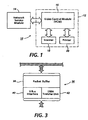
- the printing system 10 includes a printing machine 12 operatively coupled with a network service module 14.
- the printing machine 12 includes an electronic subsystem 16, referred to as a video control module (VCM), communicating with a scanner 18 and a printer 20.
- VCM video control module
- the VCM 16 which will be described in further detail below, coordinates the operation of the scanner and printer in a digital copying arrangement.
- the scanner 18 also referred to as image input terminal (IIT)
- IIT image input terminal
- an image processing system 22 ( Figure 2), associated with the scanner 18, executes signal correction and the like, converts the corrected signals into multi-level signals (e.g. binary signals), compresses the multi-level signals and preferably stores the same in electronic precollation (EPC) memory 24.
- EPC electronic precollation
- the printer 20 (also referred to as image output terminal (IOT)) preferably includes a xerographic print engine.
- the print engine has a multi-pitch belt (not shown) which is written on with an imaging source, such as a synchronous source (e.g. laser raster output scanning device) or an asynchronous source (e.g. LED print bar).
- an imaging source such as a synchronous source (e.g. laser raster output scanning device) or an asynchronous source (e.g. LED print bar).
- the multi-level image data is read out of the EPC memory 24 ( Figure 2) while the imaging source is turned on and off, in accordance with the image data, forming a latent image on the photoreceptor.
- the latent image is developed with, for example, a hybrid jumping development technique and transferred to a print media sheet.
- the printer can assume other forms besides a xerographic print engine without altering the concept upon which the disclosed embodiment is based.
- the printing system 10 could be implemented with a thermal ink jet or ionographic printer.
- the VCM 16 includes a video bus (VBus) 28 with which various I/O, data transfer and storage components communicate.
- VBus is a high speed, 32 bit data burst transfer bus which is expandable to 64 bit.
- the 32 bit implementation has a sustainable maximum bandwidth of approximately 60 MBytes/sec. In one example, the bandwidth of the VBus is as high as 100 MBytes/sec.
- the storage components of the VCM reside in the EPC memory section 30 and the mass memory section 32.
- the EPC memory section includes the EPC memory 24, the EPC memory being coupled with the VBus by way of a DRAM controller 33.
- the EPC memory which is preferably DRAM, provides expansion of up to 64 MBytes, by way of two high density 32 bit SIMM modules.
- the mass memory section 32 includes a SCSI hard drive device 34 coupled to the VBus by way of a transfer module 36a.
- transfer module 36a As will appear, other I/O and processing components are coupled respectively to the VBus by way of transfer modules 36. It will be appreciated that other devices (e.g. a workstation) could be coupled to the VBus by way of the transfer module 36a through use of a suitable interface and a SCSI line.
- the illustrated transfer module of Figure 3 includes a packet buffer 38, a VBus interface 40 and DMA transfer unit 42 .
- the transfer module 36 which was designed with "VHSIC" Hardware Description Language (VHDL), is a programmable arrangement permitting packets of image data to be transmitted along the VBus at a relatively high transfer rate.
- the packet buffer is programmable so that the segment or packet can be varied according to the available bandwidth of the VBus.
- the packet buffer can programmed to handle packets of up to 64 Bytes Preferably, the packet size would be reduced for times when the VBus is relatively busy and increased for times when activity on the bus is relatively low.
- Adjustment of the packet size is achieved with the VBus interface 40 and a system controller 44 ( Figure 5).
- the VBus interface is an arrangement of logical components, including, among others, address counters, decoders and state machines, which provides the transfer module with a selected degree of intelligence.
- the interface 40 communicates with the system controller to keep track of desired packet size and, in turn, this knowledge is used to adjust the packet size of the packet buffer 38, in accordance with bus conditions. That is, the controller, in view of its knowledge regarding conditions on the VBus 28, passes directives to the interface 40 so that the interface can adjust packet size accordingly. Further discussion regarding operation of the transfer module 36 is provided below
- each DMA transfer unit employs a conventional DMA transfer strategy to transfer the packets.
- the beginning and end addresses of the packet are used by the transfer unit in implementing a given transfer.
- the interface 40 transmits a signal back to the system controller 44 so that further information, such as desired packet size and address designations, can be obtained.
- FIG. 1 and 2 three I/O components are shown as being coupled operatively to the VBus 28, namely a FAX module 48, the scanner or IIT 18, and the printer or IOT 20; however, it should be recognized that a wide variety of components could be coupled to the VBus by way an expansion slot 50.
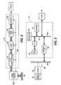
- a FAX module 48 which is coupled to the VBus 28 by way of transfer module 36b, is discussed in further detail.
- a facsimile device (FAX) 51 includes a chain of components, namely a section 52 for performing Xerox adaptive compression/decompression, a section 54 for scaling compressed image data, a section 56 for converting compressed image data to or from CCITT format, and a modem 58, preferably manufactured by Rockwell Corporation, for transmitting CCITT formatted data from or to a telephone, by way of a conventional communication line.
- a facsimile device (FAX) 51 includes a chain of components, namely a section 52 for performing Xerox adaptive compression/decompression, a section 54 for scaling compressed image data, a section 56 for converting compressed image data to or from CCITT format, and a modem 58, preferably manufactured by Rockwell Corporation, for transmitting CCITT formatted data from or to a telephone, by way of a conventional communication line.
- each of the sections 52, 54 and 56 as well as modem 58 are coupled with the transfer module 36b by way of a control line 60.
- This permits transfers to be made to and from the FAX module 48 without involving a processor.
- the transfer module 36b can serve as a master or slave for the FAX module in that the transfer module can provide image data to the FAX for purposes of transmission or receive an incoming FAX. In operation, the transfer module 36b reacts to the FAX module in the same manner that it would react to any other I/O component.
- the transfer module 36b feeds packets to the section 52 through use of the DMA transfer unit 42 and, once a packet is fed, the transfer module transmits an interrupt signal to the system processor 44 requesting another packet.
- the transfer module 36b two packets are maintained in the packet buffer 38 so that "ping-ponging" can occur between the two packets. In this way, the transfer module 36b does not run out of image data even when the controller cannot get back to it immediately upon receiving an interrupt signal.
- the IIT 18 and IOT 20 are operatively coupled to the VBus 28 by way of transfer modules 36c and 36d. Additionally, the IIT 18 and the IOT 20 are operatively coupled with a compressor 62 and a decompressor 64, respectively.
- the compressor and decompressor are preferably provided by way of a single module that employs Xerox adaptive compression devices. Xerox adaptive compression devices have been used for compression/decompression operations by Xerox Corporation in its DocuTech® printing system. In practice, at least some of the functionality of the transfer modules is provided by way of a 3 channel DVMA device, which device provides local arbitration for the compression/decompression module.
- the scanner 18, which includes the image processing section 22, is coupled with an annotate/merge module 66.
- the image processing section includes one or more dedicated processors programmed to perform various desired functions, such as image enhancement, thresholding/screening, rotation, resolution conversion and TRC adjustment.
- the selective activation of each of these functions can be coordinated by a group of image processing control registers, the registers being programmed by the system controller 44.
- the functions are arranged along a "pipeline" in which image data is inputted to one end of the pipe, and image processed image data is outputted at the other end of the pipe.
- transfer module 36e is positioned at one end of the image processing section 22 and transfer module 36c is positioned at another end of the section 22. As will appear, positioning of transfer modules 36c and 36e in this manner greatly facilitates the concurrency of a loopback process.
- arbitration of the various bus masters of the VCM 16 is implemented by way of a VBus arbiter 70 disposed in a VBus arbiter/bus gateway 71.
- the arbiter determines which bus master (e.g. FAX module, Scanner, Printer, SCSI Hard Drive, EPC Memory or Network Service Component) can access the VBus at one given time.
- the arbiter is made up of two main sections and a third control section. The first section, i.e., the "Hi-Pass" section, receives input bus requests and current priority selection, and outputs a grant corresponding to the highest priority request pending.
- the current priority selection input is the output from the second section of the arbiter and is referred to as "Priority Select".
- This section implements priority rotation and selection algorithm.
- the output of the logic for priority select determines the order in which pending requests will be serviced.
- the input to Priority Select is a register which holds an initial placement of devices on a priority chain. On servicing requests, this logic moves the devices up and down the priority chain thereby selecting the position of a device's next request.
- Control logic synchronizes the tasks of the Hi-Pass and the Priority Select by monitoring signals regarding request/grant activity. It also prevents the possibility of race conditions.
- the network service module 14 is discussed in further detail.
- the architecture of the network service module is similar to that of a known "PC clone". More particularly, in the preferred embodiment, the controller 44, which preferably assumes the form of a SPARC processor, manufactured by Sun Microsystems, Inc., is coupled with a standard SBus 72.
- a host memory 74 which preferably assumes the form of DRAM, and a SCSI disk drive device 76 are coupled operatively to the SBus 72.
- a storage or I/O device could be coupled with the SBus with a suitable interface chip.
- the SBus is coupled with a network 78 by way of an appropriate network interface 80.
- the network interface includes all of the hardware and software necessary to relate the hardware/software components of the controller 44 with the hardware/software components of the network 78.
- the network interface could be provided with, among other software, Netware® from Novell Corp.
- the network 78 includes a client, such as a workstation 82 with an emitter or driver 84.
- a user may generate a job including a plurality of electronic pages and a set of processing instructions.
- the job is converted, with the emitter, into a representation written in a page description language, such as PostScript.
- the job is then transmitted to the controller 44 where it is interpreted with a decomposer, such as one provided by Adobe Corporation.
- the network service module 14 is coupled with the VCM 16 via a bus gateway 88 of the VBus arbiter/bus gateway 71.
- the bus gateway comprises a field programmable gate array provided by XILINX corporation.
- the bus gateway device provides the interface between the host SBus and the VCM VBus. It provides VBus address translation for accesses to address spaces in the VBus real address range, and passes a virtual address to the host SBus for virtual addresses in the host address range.
- a DMA channel for memory to memory transfers is also implemented in the bus gateway.
- the bus gateway provides seamless access between the VBus and SBus, and decodes virtual addresses from bus masters, such as one of the transfer modules 36, so that an identifier can be obtained from a corresponding slave component. It will be appreciated by those skilled in the art that many components of the printing system 10 are implemented in the form of a single ASIC.
- each block comprises a plurality of packets.
- one of the transfer modules 36 is provided, by the controller 44, with the beginning address of a block and the size of the block.
- the transfer module 36 effects a packet tranfer and increments/decrements a counter. This procedure is repeated for each packet of the block until the interface 40 determines, by reference to the counter, that the last packet of the block has been transferred.
- several blocks are transferred, in a packet-by-packet manner, as described immediately above.
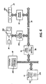
- the controller 44 includes a resource manager 300, while the host memory 74 includes a pair of lists 302, referred to respectively as the "free block list” and the “free partial block list", and a database (“db") 304.
- the resource manager is implemented by way of suitable algorithms, the details of which will be discussed in further detail below, and the significance of the lists and the database, relative to the resource management scheme, will also be discussed below.
- the EPC memory 24 and the SCSI hard drive (“disk”) 34 are shown as being comprised of blocks 306. A discussion of a methodology for forming and allocating memory blocks follows:
- the EPC memory 24 is partitioned into a series of the blocks 306.
- a partitioned set of memory blocks is also shown in Figure 11.
- the block size is varied in accordance with factors, such as image size to be stored. For example, if a location generally copies complex documents which results in poorly compressed (large) image, the block size can be increased. As will appear from the discussion below, increased block size will result in fewer interrupts by a client (e.g. scanner 18) of the controller 44.
- each block is then provided with identification information (step 310), such as block ID, block address and block size, which identification information is placed, at step 312, in the free block list.
- each list in the host memory 74 is a linked list of structures.
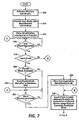
- the resource management system waits for a memory request from a client.
- a client is an input or output device encompassed by the printing system 10 ( Figures 1,2 and 5).
- a client initiates a request by transmitting a suitable request or interrupt signal to the controller 44.
- the controller determines, via step 316, whether the client is an input client. If the client is an input client, then the process proceeds to step 318, otherwise the process proceeds directly to step 320 ( Figure 9) where an output client request is serviced.
- the resource manager 300 examines the free partial block list to determine if a partial block is available for the requesting client.
- a partial block is available for the requesting client.
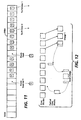
- FIG 12 an example of the allocation of a partial block to the beginning of an image will be discussed.
- image data for image 1 is delivered to the memory, however, a partial, unfilled block may remain.
- the partially unfilled block, with its corresponding identifier is made available for use with the next image.
- a partial, unfilled block is available, then it is designated with an identifier and, at step 322, placed in the db 304.
- the resource manager consults the free block list to determine if a nominal number of blocks are available for use by the input client.
- each client is assigned a value corresponding to the number of nominal blocks to which it is entitled.
- assignment is based on the processing speed of the requesting client. That is, per each request, it may be desirable to provide fast processing clients with more blocks than slow processing clients.
- the nominal number of blocks to be assigned a requesting client may not be available in the free block list. In this situation, the resource manager may provide the requesting client with one or more partial blocks until a whole block becomes available.
- the resource manager will place appropriate identifiers (i.e. information identifying both a first address and a size of each block) in the db 304.
- appropriate identifiers i.e. information identifying both a first address and a size of each block
- the database is constructed in a hierarchical scheme in which jobs are linked to images and images are linked to blocks.
- the client's storable image data is associated with a first image (i.e. "Image 1) of a first job (i.e. "JOB 1”)
- the first block identifier is placed at the location designated as "Block 1 Address”.
- the client will access the database and, at step 328 ( Figure 7), locate the address of the first available block.
- the client will then, in cooperation with, for example, one of transfer modules 36, fill up the located block.
- the scanner When the scanner is serving as the client, the scanner will initiate a DMA transfer, with EPC memory 24, via the transfer module 36D ( Figure 2).
- the scanner is shown as using the EPC memory in conjunction with other clients. While the block 306A is shown as being a whole block, it will be understood that, in many instances, it would be a partial block.
- the printing system 10 offers the advantageous feature of storing jobs, intended to be outputted as multiple sets, on disk. In this way EPC memory can be made available to multiple clients in a relatively short time interval.
- step 332 of Figure 8 when disk storage is desired, each stored block is copied to disk 34 (also see step 334 of Figure 8).
- Figure 14 a graphic representation demonstrating the relationship between EPC memory and disk is provided.
- a minimum amount of input image pages, intended for printing are buffered prior to printing. This has been found to be advantageous since a printer typically processes image data at a rate much greater than that of most input clients, such as the scanner.
- a variable buffer zone 336 is maintained for the scan client. This buffer zone is used to move image directly to disk, which enables the system to continue scanning without stopping. It will be appreciated that the variable zone can be used by clients, other than the scanner 18, to facilitate storage.
- the input client transmits an interrupt signal to the controller, at step 338, when a block has been filled with image data.
- the input client could be provided, in advance, with pointers to lists of block addresses. In this way, the input client would read, without controller intervention, the locations of blocks to be used.
- step 328 where the db 304 ( Figure 6) is accessed so that the client can locate the next block to be filled.
- the process loops back to step 324 for obtaining at least a part of another block set.
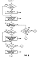
- step 340 if it is determined, at step 340, that a full image has just been written into memory, then a series of steps is performed to prepare for the receiving of another image.
- the resource manager 300 determines, with step 344, if all of the full blocks have been used by the input client. If not, then the identifier of each surplus whole block is placed in the free block list (step 348), otherwise the process proceeds to step 350 where the resource manager determines if the image ends on a partial block. Referring again to Figure 12, an example of how an image might end at a partial block is shown for the "Image 1". In the preferred embodiment, the size of the unused part of Image 1 is then determined in accordance with step 352 of Figure 8.
- step 354 if the size of the partial block is greater than a selected minimum size (step 354), then an identifier is assigned to the partial block (step 356) and placed in the free partial block list so that the partial block can be used to receive image data from another image, such as the "Next Image" of Figure 12. For those cases in which a given partial block is smaller than a selected minimum, the given partial block is saved for "garbage collection", the significance of which will be described below.
- the preferred methodology accommodates for the needs of an output client, such as a printer.
- the output client is preferably "told" where the image data, intended for use in outputting, resides. In this way, the output client can read the image data from the EPC memory. Additionally, as shown in Figure 14, an output operation can be executed just before or after an input operation.
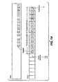
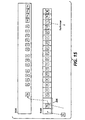
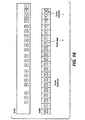
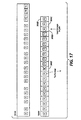
- FIGs 14, 16 and 17 an application of the the present memory management scheme, with respect to the printing client, is discussed in further detail.
- a given job intended to be printed in multiple sets, is shown as including six images.
- the first three images are buffered and copied to disk.
- writing of images, to memory continues concurrent with the reading of first and second image blocks by the printer. While the read/write operations are not "concurrent", in absolute terms, they appear, to a system operator, as being concurrent.
- the end of the job is written into EPC memory at blocks 306B, 306C and 306D, while the beginning of the printing of a second set is initiated at block 306E.
- the image 2 along with the block for 1D need not be copied from disk.
- the EPC memory and disk function in a manner comparable to a ring buffering arrangement in that image data from disk can be written over image data in the EPC memory, continually, in order to form a desired number of sets.
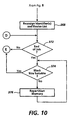
- garbage collection refers to combining "spent blocks", i.e. blocks having image data already “consumed” by an output client, for future use.
- a check for garbage collection is performed after a predesignated number of images have been printed. More particularly, garbage collection is performed as a background task, i.e. during a noncritical time of a job cycle.
- block combination constitutes, in one example, linking partial blocks with references.
- blocks are formed from partial blocks (step 368), some partial block identifiers will be discarded and the resulting whole block will be placed in the free block list. If garbage collection is not performable, the process proceeds to step 372.
- a check is performed to determine if the currently completed image is the last image in the job. If the image is not the last image, then the process loops back to step 316 where the input/output client accesses the db 304 for another block identifier, assuming that the client is ready. If, on the other hand, the job is complete, then a determination is made, at step 374, as to whether repartitioning is required. Repartitioning is performed (step 376) until a suitable block size is obtained. Subsequent to repartitioning the process loops back to step 316.
- the disclosed resource management scheme functions with a minimum amount of processing overhead.
- block identifiers are placed at selected locations in a database.
- a selected client can access the database, determine where available blocks exist in memory, by reference to the block identifiers, and begin filling those blocks.
- the client signals a controller and, in response to the signals, the controller indicates to a resource manager when to place more block identifiers in the database for the selected client.
- the process of providing blocks is transparent to the selected client and the resource manager is not required to possesses any significant knowledge about memory allocations of system clients in order to service the selected client appropriately.
- memory utilization of the system is enhanced in that memory blocks are employed in a particularly efficient manner. That is, unused blocks, whether they be partial or whole blocks, are placed in one or more free lists as soon as a given client ceases to have an immediate need for them. In turn, unused free blocks are allocated to other clients, in an expeditious manner and partial blocks are, in many instances, used to store the beginning and end parts of an image. In this way memory fragmentation is minimized and memory space is made available to clients, who have an urgent demand for it, as soon as possible.
- the resource management technique is flexible in that a wide variety of system parameters, such as nominal block size, number of blocks allocated to a given client at one time, and block allocation timing are variable.
- the system can keep track of compression ratios and adjust the variables to maximize performance for a particular location's majority usage. For example, if a location generally copies complex documents, which results in poorly compressed (large) images, the block size can be increased. Use of increased block size will result in fewer interrupts to the controller.
- the system can, among other things, adjust block allocation according to individual client processing capability and predict the moment at which blocks, for a given client, should be made available.
- the resource management scheme can be used to coincidentally manage volatile and nonvolatile memory in a manner that maximizes the functionality of the volatile memory, which volatile memory may be limited in space.
- volatile memory e.g. EPC memory
- volatile and nonvolatile memory can be used, conjunctively, to insure that even complex documents, having much greater size than that of the volatile memory, can be stored by a given input client without impairing operation of that given input client.
Applications Claiming Priority (2)
| Application Number | Priority Date | Filing Date | Title |
|---|---|---|---|
| US08/315,274 US5579452A (en) | 1994-09-29 | 1994-09-29 | Method of managing memory allocation in a printing system |
| US315274 | 1994-09-29 |
Publications (2)
| Publication Number | Publication Date |
|---|---|
| EP0704792A1 EP0704792A1 (en) | 1996-04-03 |
| EP0704792B1 true EP0704792B1 (en) | 2001-06-13 |
Family
ID=23223657
Family Applications (1)
| Application Number | Title | Priority Date | Filing Date |
|---|---|---|---|
| EP95306919A Expired - Lifetime EP0704792B1 (en) | 1994-09-29 | 1995-09-29 | Method of managing memory allocation in a printing system |
Country Status (6)
| Country | Link |
|---|---|
| US (2) | US5579452A (ja) |
| EP (1) | EP0704792B1 (ja) |
| JP (1) | JPH08112946A (ja) |
| BR (1) | BR9504218A (ja) |
| CA (1) | CA2153827C (ja) |
| DE (1) | DE69521256T2 (ja) |
Families Citing this family (36)
| Publication number | Priority date | Publication date | Assignee | Title |
|---|---|---|---|---|
| IL116988A (en) * | 1996-01-31 | 1999-12-31 | Galileo Technology Ltd | Bus protocol |
| US5797043A (en) * | 1996-03-13 | 1998-08-18 | Diamond Multimedia Systems, Inc. | System for managing the transfer of data between FIFOs within pool memory and peripherals being programmable with identifications of the FIFOs |
| JP3806987B2 (ja) * | 1996-08-26 | 2006-08-09 | ブラザー工業株式会社 | 多機能周辺装置 |
| US5950231A (en) * | 1996-11-25 | 1999-09-07 | Northern Telecom Limited | Memory manager system |
| US6049870A (en) * | 1996-11-26 | 2000-04-11 | Play, Inc. | System and method for identifying and configuring modules within a digital electronic device |
| US5870535A (en) * | 1997-05-12 | 1999-02-09 | Lexmark International, Inc. | Method and apparatus for building rasterized lines of bitmap data to be printed using a piecewise-linear direct memory access addressing mode of retrieving bitmap data line segments |
| US6023343A (en) * | 1997-08-29 | 2000-02-08 | Lexmark International, Inc. | Method and apparatus for temporary storage on disk of collated print data |
| US5970222A (en) * | 1998-01-08 | 1999-10-19 | Xerox Corporation | Memory management system for printing a print job with limited capacity |
| JP3688483B2 (ja) * | 1998-11-13 | 2005-08-31 | シャープ株式会社 | 画像出力処理装置 |
| JP2001209981A (ja) * | 1999-02-09 | 2001-08-03 | Ricoh Co Ltd | 光ディスク基板成膜装置、光ディスク基板成膜方法、基板ホルダーの製造方法、基板ホルダー、光ディスクおよび相変化記録型光ディスク |
| US6488423B1 (en) | 1999-11-03 | 2002-12-03 | Toshiba Tec Kabushiki Kaisha | Synchronous printing |
| US6671065B1 (en) * | 1999-11-29 | 2003-12-30 | Xerox Corporation | Method and apparatus to optimize transition of resources from a lower priority to a higher priority job |
| US6463481B1 (en) | 1999-12-02 | 2002-10-08 | Xerox Corporation | Direct memory access control system for a digital scanner |
| US6401143B1 (en) | 1999-12-02 | 2002-06-04 | Xerox Corporation | Loopback direct memory access control system for a digital scanner |
| US6738158B1 (en) | 1999-12-02 | 2004-05-18 | Xerox Corporation | Digital scanner for capturing and processing images |
| JP4479054B2 (ja) * | 1999-12-14 | 2010-06-09 | コニカミノルタビジネステクノロジーズ株式会社 | デジタル複写機およびデジタル複写機における画像データの転送方法 |
| US7324228B2 (en) | 2000-02-25 | 2008-01-29 | Hewlett-Packard Development Company, L.P. | System and method for downloading and for printing data from an external content source |
| GB2359642B (en) * | 2000-02-25 | 2005-02-02 | Hewlett Packard Co | Printing a plurality of data files |
| US6665098B1 (en) | 2000-02-28 | 2003-12-16 | Xerox Corporation | Dynamic user interface based on frequency of user settings |
| US6856420B1 (en) * | 2000-07-31 | 2005-02-15 | Hewlett-Packard Development Company, L.P. | System and method for transferring data within a printer |
| JP4538191B2 (ja) * | 2001-03-15 | 2010-09-08 | セイコーエプソン株式会社 | 画像処理装置 |
| US20040169885A1 (en) * | 2003-02-28 | 2004-09-02 | Mellor Douglas J. | Memory management |
| US7085910B2 (en) * | 2003-08-27 | 2006-08-01 | Lsi Logic Corporation | Memory window manager for control structure access |
| US9323571B2 (en) * | 2004-02-06 | 2016-04-26 | Intel Corporation | Methods for reducing energy consumption of buffered applications using simultaneous multi-threading processor |
| CN1918879B (zh) * | 2004-02-19 | 2014-06-25 | 艾利森电话股份有限公司 | 用于状态存储器管理的方法和装置 |
| JP4323995B2 (ja) * | 2004-03-25 | 2009-09-02 | キヤノン株式会社 | データ処理装置及びその制御方法 |
| JP4144878B2 (ja) * | 2004-03-25 | 2008-09-03 | キヤノン株式会社 | データ処理装置及びデータ処理方法並びにコンピュータプログラム |
| US7684076B2 (en) | 2004-07-23 | 2010-03-23 | Kabushiki Kaisha Toshiba | Method and apparatus for raster image processing |
| US20070236582A1 (en) * | 2006-03-29 | 2007-10-11 | Imaging Solutions Group Of Ny, Inc. | Video camera with multiple independent outputs |
| US20080052261A1 (en) * | 2006-06-22 | 2008-02-28 | Moshe Valenci | Method for block level file joining and splitting for efficient multimedia data processing |
| US8166212B2 (en) * | 2007-06-26 | 2012-04-24 | Xerox Corporation | Predictive DMA data transfer |
| US8218177B2 (en) * | 2007-11-09 | 2012-07-10 | Xerox Corporation | Resource management profiles |
| US8271988B2 (en) * | 2007-11-09 | 2012-09-18 | Xerox Corporation | System-generated resource management profiles |
| US8205020B2 (en) * | 2009-12-23 | 2012-06-19 | Xerox Corporation | High-performance digital image memory allocation and control system |
| KR101835604B1 (ko) * | 2011-06-03 | 2018-03-07 | 삼성전자 주식회사 | 메모리를 위한 스케줄러 |
| US10178273B2 (en) * | 2016-12-22 | 2019-01-08 | Kabushiki Kaisha Toshiba | Image data conversion based on actual size |
Family Cites Families (27)
| Publication number | Priority date | Publication date | Assignee | Title |
|---|---|---|---|---|
| US3597071A (en) * | 1968-08-30 | 1971-08-03 | Xerox Corp | Diverse-input system for electrostatically reproducing and recording information |
| CA1086231A (en) * | 1976-03-08 | 1980-09-23 | Lee N. Davy | Document copying apparatus with electronic collating memory |
| JP2733220B2 (ja) * | 1986-09-30 | 1998-03-30 | シャープ株式会社 | 複合型画像処理装置 |
| US4821107A (en) * | 1987-01-26 | 1989-04-11 | Minolta Camera Kabushiki Kaisha | Multi-functional imaging apparatus |
| US5047955A (en) * | 1987-06-19 | 1991-09-10 | Eastman Kodak Company | Electronic collation |
| US5351074A (en) * | 1988-01-19 | 1994-09-27 | Canon Kabushiki Kaisha | Apparatus for forming a color image using two memories |
| US5047957A (en) * | 1988-10-21 | 1991-09-10 | Minolta Camera Kabushiki Kaisha | Printer controller |
| US5029109A (en) * | 1989-02-23 | 1991-07-02 | Minolta Camera Kabushiki Kaisha | Image forming device with a small sized memory device employing a bit map assignment system |
| US5220645A (en) * | 1989-03-07 | 1993-06-15 | Canon Kabushiki Kaisha | Output apparatus |
| US5109336A (en) * | 1989-04-28 | 1992-04-28 | International Business Machines Corporation | Unified working storage management |
| US5159681A (en) * | 1989-08-11 | 1992-10-27 | Lexmark International, Inc. | Page printer memory allocation |
| WO1991006058A1 (en) * | 1989-10-10 | 1991-05-02 | Unisys Corporation | Storage and retrieval system for document image data |
| US5414826A (en) * | 1990-01-31 | 1995-05-09 | Hewlett-Packard Company | System and method for memory management in microcomputer |
| US5170340A (en) * | 1990-09-28 | 1992-12-08 | Xerox Corporation | System state controller for electronic image processing systems |
| US5212566A (en) * | 1990-09-28 | 1993-05-18 | Xerox Corporation | Synchronization of ess/iit when scanning complex documents |
| US5223948A (en) * | 1990-10-10 | 1993-06-29 | Fuji Xerox Co., Ltd. | Image processing apparatus |
| US5301262A (en) * | 1990-10-10 | 1994-04-05 | Fuji Xerox Co., Ltd. | Image processor |
| US5175633A (en) * | 1990-10-10 | 1992-12-29 | Fuji Xerox Co., Ltd. | Method of diagnosing operating conditions of an image processor |
| US5339411A (en) * | 1990-12-21 | 1994-08-16 | Pitney Bowes Inc. | Method for managing allocation of memory space |
| KR940002475B1 (ko) * | 1991-08-20 | 1994-03-24 | 삼성전자 주식회사 | 화면편집장치 |
| US5276799A (en) * | 1991-10-29 | 1994-01-04 | Xerox Corporation | Expandable electronic subsystem for a printing machine |
| JP3020699B2 (ja) * | 1991-12-04 | 2000-03-15 | キヤノン株式会社 | 印刷装置 |
| US5307458A (en) * | 1991-12-23 | 1994-04-26 | Xerox Corporation | Input/output coprocessor for printing machine |
| JPH05221030A (ja) * | 1992-02-18 | 1993-08-31 | Brother Ind Ltd | 印刷制御装置 |
| US5530840A (en) * | 1993-12-09 | 1996-06-25 | Pitney Bowes Inc. | Address decoder with memory allocation for a micro-controller system |
| US5568634A (en) * | 1994-04-21 | 1996-10-22 | Gemplus Card International | Method of writing in a non-volatile memory, notably in a memory card employing memory allocation strategies on size and occupancy basis |
| US5606688A (en) * | 1994-08-31 | 1997-02-25 | International Business Machines Corporation | Method and apparatus for dynamic cache memory allocation via single-reference residency times |
-
1994
- 1994-09-29 US US08/315,274 patent/US5579452A/en not_active Expired - Lifetime
-
1995
- 1995-07-13 CA CA002153827A patent/CA2153827C/en not_active Expired - Fee Related
- 1995-09-20 JP JP24122395A patent/JPH08112946A/ja active Pending
- 1995-09-28 BR BR9504218A patent/BR9504218A/pt not_active IP Right Cessation
- 1995-09-29 DE DE69521256T patent/DE69521256T2/de not_active Expired - Lifetime
- 1995-09-29 EP EP95306919A patent/EP0704792B1/en not_active Expired - Lifetime
-
1996
- 1996-08-23 US US08/701,900 patent/US5717842A/en not_active Expired - Lifetime
Also Published As
| Publication number | Publication date |
|---|---|
| DE69521256D1 (de) | 2001-07-19 |
| BR9504218A (pt) | 1996-07-30 |
| CA2153827A1 (en) | 1996-03-30 |
| JPH08112946A (ja) | 1996-05-07 |
| DE69521256T2 (de) | 2001-09-27 |
| US5579452A (en) | 1996-11-26 |
| EP0704792A1 (en) | 1996-04-03 |
| CA2153827C (en) | 1999-06-01 |
| US5717842A (en) | 1998-02-10 |
Similar Documents
| Publication | Publication Date | Title |
|---|---|---|
| EP0704792B1 (en) | Method of managing memory allocation in a printing system | |
| EP0704791B1 (en) | Method of processing a job, in a printing system, with a composite job ticket | |
| US5627658A (en) | Automatic networked facsimile queuing system | |
| US5923826A (en) | Copier/printer with print queue disposed remotely thereof | |
| JP4101860B2 (ja) | 多機能印刷システムのための割込システム | |
| EP0873007B1 (en) | Multifunctional printing system with queue management | |
| CA2154498C (en) | Apparatus and method for maximizing a rate of image data transfer in a printing system | |
| US5920685A (en) | Printing machine with merging/annotating/signaturizing capability | |
| JPH08235003A (ja) | 印刷ジョブを印刷する総時間を見積もるための装置及び方法 | |
| JPH10289074A (ja) | 多機能印刷システムにおけるジョブ処理管理方法 | |
| US5659634A (en) | Apparatus and method for encoding and reconstructing image data | |
| US6671065B1 (en) | Method and apparatus to optimize transition of resources from a lower priority to a higher priority job | |
| US6651081B1 (en) | Method and apparatus for processing a high priority resource request in a system using a set of shared resources | |
| US5894586A (en) | System for providing access to memory in which a second processing unit is allowed to access memory during a time slot assigned to a first processing unit | |
| US6717690B1 (en) | Method and apparatus for managing job contention for system resources in an electrographic reproduction system where images are multibanded | |
| EP1104172B1 (en) | Method and apparatus to enable job streaming for a set of commonly shared resources | |
| US5970222A (en) | Memory management system for printing a print job with limited capacity | |
| US6762857B1 (en) | Method and apparatus to enable processing multiple capabilities for a sub-job when using a set of commonly shared resources | |
| US6501559B1 (en) | Method and apparatus for managing job contention for system resources in an electronic reprographic system | |
| CA2156137C (en) | Programmable arbitrating apparatus | |
| US6614542B1 (en) | Method and apparatus to improve system concurrency for a job using a set of commonly shared resources such that a specific resource is used only for a portion of the job | |
| US5668938A (en) | Control system for programming first print out time in a printing system | |
| JP3809284B2 (ja) | 画像生成装置及びその制御方法及び印刷装置 |
Legal Events
| Date | Code | Title | Description |
|---|---|---|---|
| PUAI | Public reference made under article 153(3) epc to a published international application that has entered the european phase |
Free format text: ORIGINAL CODE: 0009012 |
|
| AK | Designated contracting states |
Kind code of ref document: A1 Designated state(s): DE FR GB |
|
| 17P | Request for examination filed |
Effective date: 19961004 |
|
| 17Q | First examination report despatched |
Effective date: 19991124 |
|
| GRAG | Despatch of communication of intention to grant |
Free format text: ORIGINAL CODE: EPIDOS AGRA |
|
| GRAG | Despatch of communication of intention to grant |
Free format text: ORIGINAL CODE: EPIDOS AGRA |
|
| GRAH | Despatch of communication of intention to grant a patent |
Free format text: ORIGINAL CODE: EPIDOS IGRA |
|
| GRAH | Despatch of communication of intention to grant a patent |
Free format text: ORIGINAL CODE: EPIDOS IGRA |
|
| GRAA | (expected) grant |
Free format text: ORIGINAL CODE: 0009210 |
|
| AK | Designated contracting states |
Kind code of ref document: B1 Designated state(s): DE FR GB |
|
| REF | Corresponds to: |
Ref document number: 69521256 Country of ref document: DE Date of ref document: 20010719 |
|
| ET | Fr: translation filed | ||
| REG | Reference to a national code |
Ref country code: GB Ref legal event code: IF02 |
|
| PLBE | No opposition filed within time limit |
Free format text: ORIGINAL CODE: 0009261 |
|
| STAA | Information on the status of an ep patent application or granted ep patent |
Free format text: STATUS: NO OPPOSITION FILED WITHIN TIME LIMIT |
|
| 26N | No opposition filed | ||
| PGFP | Annual fee paid to national office [announced via postgrant information from national office to epo] |
Ref country code: DE Payment date: 20130820 Year of fee payment: 19 |
|
| PGFP | Annual fee paid to national office [announced via postgrant information from national office to epo] |
Ref country code: GB Payment date: 20130823 Year of fee payment: 19 |
|
| PGFP | Annual fee paid to national office [announced via postgrant information from national office to epo] |
Ref country code: FR Payment date: 20130920 Year of fee payment: 19 |
|
| REG | Reference to a national code |
Ref country code: DE Ref legal event code: R119 Ref document number: 69521256 Country of ref document: DE |
|
| GBPC | Gb: european patent ceased through non-payment of renewal fee |
Effective date: 20140929 |
|
| REG | Reference to a national code |
Ref country code: DE Ref legal event code: R119 Ref document number: 69521256 Country of ref document: DE Effective date: 20150401 |
|
| REG | Reference to a national code |
Ref country code: FR Ref legal event code: ST Effective date: 20150529 |
|
| PG25 | Lapsed in a contracting state [announced via postgrant information from national office to epo] |
Ref country code: GB Free format text: LAPSE BECAUSE OF NON-PAYMENT OF DUE FEES Effective date: 20140929 Ref country code: DE Free format text: LAPSE BECAUSE OF NON-PAYMENT OF DUE FEES Effective date: 20150401 |
|
| PG25 | Lapsed in a contracting state [announced via postgrant information from national office to epo] |
Ref country code: FR Free format text: LAPSE BECAUSE OF NON-PAYMENT OF DUE FEES Effective date: 20140930 |