EP0704401A2 - Spinnkanne mit beweglichem Boden für Fäden und/oder Fasern - Google Patents
Spinnkanne mit beweglichem Boden für Fäden und/oder Fasern Download PDFInfo
- Publication number
- EP0704401A2 EP0704401A2 EP95830388A EP95830388A EP0704401A2 EP 0704401 A2 EP0704401 A2 EP 0704401A2 EP 95830388 A EP95830388 A EP 95830388A EP 95830388 A EP95830388 A EP 95830388A EP 0704401 A2 EP0704401 A2 EP 0704401A2
- Authority
- EP
- European Patent Office
- Prior art keywords
- spinning
- movable
- movable bottom
- fibres
- rods
- Prior art date
- Legal status (The legal status is an assumption and is not a legal conclusion. Google has not performed a legal analysis and makes no representation as to the accuracy of the status listed.)
- Withdrawn
Links
Images

Classifications
-
- B—PERFORMING OPERATIONS; TRANSPORTING
- B65—CONVEYING; PACKING; STORING; HANDLING THIN OR FILAMENTARY MATERIAL
- B65H—HANDLING THIN OR FILAMENTARY MATERIAL, e.g. SHEETS, WEBS, CABLES
- B65H75/00—Storing webs, tapes, or filamentary material, e.g. on reels
- B65H75/02—Cores, formers, supports, or holders for coiled, wound, or folded material, e.g. reels, spindles, bobbins, cop tubes, cans, mandrels or chucks
- B65H75/04—Kinds or types
- B65H75/16—Cans or receptacles, e.g. sliver cans
-
- B—PERFORMING OPERATIONS; TRANSPORTING
- B65—CONVEYING; PACKING; STORING; HANDLING THIN OR FILAMENTARY MATERIAL
- B65H—HANDLING THIN OR FILAMENTARY MATERIAL, e.g. SHEETS, WEBS, CABLES
- B65H2701/00—Handled material; Storage means
- B65H2701/30—Handled filamentary material
- B65H2701/31—Textiles threads or artificial strands of filaments
Definitions
- the present invention relates to a movable-bottom spinning can for yarns and/or fibres.
- the above mentioned can or vats are filled-in by fibres, and are provided with side fixed walls and a movable bottom which is lowered and raised depending on the weight exerted thereon.
- This bottom tends to downwardly move under the weight of the textile fibres, introduced into said cans and/or vats.
- the cans are progressively emptied, and since, as it should be apparent, the weight of the fibres tends to decrease, the movable bottom, biassed by urging springs, tends to raise so as to always hold at an upward position the roving and/or textile fibres to be processed.
- the upward location of the roving and/or fibres is such as to hold the roving always at an optimum position to be taken up from the can.
- the aim of the present invention is to overcome the above mentioned problems, by providing a movable-bottom spinning can for yarns and/or fibres, the movable bottom of which can be always displaced with a parallel relationship to itself, thereby overcoming the problem of undesired unbalanced loads.
- a main object of the present invention is to provide such a parallelepipedal shape spinning can, in which the movable bottom is always prevented from being undesirably slanted, even if the yarn or fibre load is taken up in an unbalanced manner.
- Another object of the present invention is to provide such a movable bottom yarn and/or fibre spinning can which, owing to its specific construction features, is very reliable and safe in operation.
- Yet another object of the present invention is to provide such a spinning can which can be easily made starting from easily available elements and materials and which, moreover, is very competitive from a mere economic standpoint.
- a movable-bottom spinning can for yarns and/or fibres comprising a holding body, including a movable bottom urged by resilient means, characterized in that said resilient means comprise a central spring arranged between pantograph elements operating between said movable bottom and a fixed bottom of said holding body.
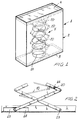
- the movable-bottom spinning frame for yarns and/or fibres which has been generally indicated by the reference number 1, comprises a holding body 2, of substantially parallelepipedal shape and including a preferably rectangular base, which is provided with a fixed bottom 3.
- a movable bottom 4 which is coupled to resilient means, generally indicated by the reference number 5.
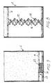
- the main feature of the invention is that the aforesaid resilient means are constituted by a central spring 10, of a coil or helical type, which is connected between the movable bottom 4 and a lower bottom 11, superimposed on the fixed bottom 3 of the body 2.
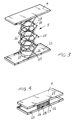
- said pantograph elements 15 comprise rods 16, mutually articulated pantograph-like, with the end rod being articulated or pivoted at 17, respectively to the movable bottom 4 and the lower bottom 11, whereas, on the other portions thereof, the rods 16 are provided with a sliding roller 18, which can be displaced in a guide seat 19.
- pantograph elements 15 are coupled to one another by cross-elements 20 which, at their intermediate positions, are rigidly coupled to the turns of the coil spring 10, so as to allow the spring to elongate in an even manner.
- the movable bottom 4 will be lowered, so as to approach the lower bottom, and the rods 16 of the pantograph will be mutually closed with a consequent sliding movement of the rollers 18 in the guide seats 19.
- the resilient operation of the spring will cause the pantograph elements 15 to be extended, so as to cause the movable bottom 4 to be displaced parallel to itself, without any jams or unbalanced effects, even in a case in which the load thereon is taken up in an uneven manner.
- the spring 10 is associated with bent wings 30 which are provided at the movable bottom and lower bottom.
- pantograph elements which practically define the spring housing region and which interconnect the movable bottom to the fixed bottom, will allow the movable bottom to be always displaced parallel to itself, under all of the use conditions.
- the used materials provided that they are compatible to the intended use, as well as the contingent size and shapes, can be any, depending on requirements.
Landscapes
- Spinning Or Twisting Of Yarns (AREA)
Applications Claiming Priority (2)
| Application Number | Priority Date | Filing Date | Title |
|---|---|---|---|
| ITMI940655 IT234133Y1 (it) | 1994-09-29 | 1994-09-29 | Vaso di filatura per filati e/o fibre, con fondo mobile |
| ITMI940655U | 1994-09-29 |
Publications (2)
| Publication Number | Publication Date |
|---|---|
| EP0704401A2 true EP0704401A2 (de) | 1996-04-03 |
| EP0704401A3 EP0704401A3 (de) | 1997-01-08 |
Family
ID=11368498
Family Applications (1)
| Application Number | Title | Priority Date | Filing Date |
|---|---|---|---|
| EP95830388A Withdrawn EP0704401A3 (de) | 1994-09-29 | 1995-09-22 | Spinnkanne mit beweglichem Boden für Fäden und/oder Fasern |
Country Status (2)
| Country | Link |
|---|---|
| EP (1) | EP0704401A3 (de) |
| IT (1) | IT234133Y1 (de) |
Cited By (2)
| Publication number | Priority date | Publication date | Assignee | Title |
|---|---|---|---|---|
| EP0811574A3 (de) * | 1996-06-07 | 1998-04-01 | Rieter Elitex A.S. Usti Nad Orlici | Flachbehälter für Faserband |
| WO2017068598A1 (en) * | 2015-10-19 | 2017-04-27 | Rimtex Industries | A sliver can and a spring assembly for a sliver can |
Family Cites Families (3)
| Publication number | Priority date | Publication date | Assignee | Title |
|---|---|---|---|---|
| IT1220889B (it) * | 1988-06-01 | 1990-06-21 | Cerit Spa | Vaso per nastri tessili |
| FR2692238B3 (fr) * | 1992-06-16 | 1994-07-22 | Suroy Freres Sa | Dispositif stabilisateur pour pot de filature non cylindrique a fond mobile. |
| DE4234793C2 (de) * | 1992-10-15 | 1994-07-21 | Rieter Ingolstadt Spinnerei | Flachkanne |
-
1994
- 1994-09-29 IT ITMI940655 patent/IT234133Y1/it active IP Right Grant
-
1995
- 1995-09-22 EP EP95830388A patent/EP0704401A3/de not_active Withdrawn
Non-Patent Citations (1)
| Title |
|---|
| None |
Cited By (2)
| Publication number | Priority date | Publication date | Assignee | Title |
|---|---|---|---|---|
| EP0811574A3 (de) * | 1996-06-07 | 1998-04-01 | Rieter Elitex A.S. Usti Nad Orlici | Flachbehälter für Faserband |
| WO2017068598A1 (en) * | 2015-10-19 | 2017-04-27 | Rimtex Industries | A sliver can and a spring assembly for a sliver can |
Also Published As
| Publication number | Publication date |
|---|---|
| EP0704401A3 (de) | 1997-01-08 |
| ITMI940655U1 (it) | 1996-03-29 |
| ITMI940655V0 (it) | 1994-09-29 |
| IT234133Y1 (it) | 2000-02-23 |
Similar Documents
| Publication | Publication Date | Title |
|---|---|---|
| JPH03151488A (ja) | 垂直にもち上がるカーテンドアを補強する補強装置 | |
| EP0704401A2 (de) | Spinnkanne mit beweglichem Boden für Fäden und/oder Fasern | |
| US6425163B1 (en) | Coiler can having a vertically movable bottom | |
| CZ285846B6 (cs) | Schránka pro svařovací drát | |
| MXPA06006081A (es) | Aparato para cubrir partes de alambre expuestas del ensamble de resortes para colchones de cama. | |
| EP0659660B1 (de) | Verfahren und Vorrichtung zur Handhabung von Papierrollen | |
| US4464891A (en) | Yarn processing machine and creel assembly | |
| US2017032A (en) | Cushion spring assembly | |
| US4403471A (en) | Bobbin exchange apparatus on a ring spinning or ring twisting machine | |
| US4324094A (en) | Semiautomatic device for doffing spools from a spindle bench | |
| WO1989007561A1 (en) | A flexible receptacle | |
| US5937484A (en) | Flat container of textile fibre sliver | |
| US2690643A (en) | Telescopic supporting device for thread guides | |
| USRE25742E (en) | Border stabilizers | |
| CN220639876U (zh) | 一种纱线加工用可调节的周转架 | |
| GB1559055A (en) | Flyer frame having means facilitating the doffing of full bobbins | |
| US2574381A (en) | Sewing machine | |
| US4571930A (en) | Automatic doffing device for ring spinning and/or twisting frames, in particular in machines for producing large packages | |
| CN218619655U (zh) | 绞线机托盘防坠机构 | |
| US3117408A (en) | Doffing device for use in spinning, twisting, doubling and like textile machines | |
| CN223561805U (zh) | 一种综丝以及圆织机 | |
| US2021528A (en) | Spring assembly for upholstery and springs therefor | |
| US1711092A (en) | Stop motion for spinning machines | |
| DE102004024691A1 (de) | Vorrichtung zur Gewichtssensierung für einen Fahrzeugsitz | |
| US1786235A (en) | Separator for ring-spinning machines |
Legal Events
| Date | Code | Title | Description |
|---|---|---|---|
| PUAI | Public reference made under article 153(3) epc to a published international application that has entered the european phase |
Free format text: ORIGINAL CODE: 0009012 |
|
| AK | Designated contracting states |
Kind code of ref document: A2 Designated state(s): DE ES FR GR PT |
|
| PUAL | Search report despatched |
Free format text: ORIGINAL CODE: 0009013 |
|
| AK | Designated contracting states |
Kind code of ref document: A3 Designated state(s): DE ES FR GR PT |
|
| 17P | Request for examination filed |
Effective date: 19970407 |
|
| 17Q | First examination report despatched |
Effective date: 19970522 |
|
| STAA | Information on the status of an ep patent application or granted ep patent |
Free format text: STATUS: THE APPLICATION IS DEEMED TO BE WITHDRAWN |
|
| 18D | Application deemed to be withdrawn |
Effective date: 19980919 |