US5184809A - Spring assembly for seating and bedding - Google Patents
Spring assembly for seating and bedding Download PDFInfo
- Publication number
- US5184809A US5184809A US07/729,734 US72973491A US5184809A US 5184809 A US5184809 A US 5184809A US 72973491 A US72973491 A US 72973491A US 5184809 A US5184809 A US 5184809A
- Authority
- US
- United States
- Prior art keywords
- runs
- spring
- wires
- springs
- coil
- Prior art date
- Legal status (The legal status is an assumption and is not a legal conclusion. Google has not performed a legal analysis and makes no representation as to the accuracy of the status listed.)
- Expired - Lifetime
Links
- 230000000712 assembly Effects 0.000 description 3
- 238000000429 assembly Methods 0.000 description 3
- 230000015556 catabolic process Effects 0.000 description 1
- 210000005069 ears Anatomy 0.000 description 1
- 238000000034 method Methods 0.000 description 1
Images

Classifications
-
- A—HUMAN NECESSITIES
- A47—FURNITURE; DOMESTIC ARTICLES OR APPLIANCES; COFFEE MILLS; SPICE MILLS; SUCTION CLEANERS IN GENERAL
- A47C—CHAIRS; SOFAS; BEDS
- A47C23/00—Spring mattresses with rigid frame or forming part of the bedstead, e.g. box springs; Divan bases; Slatted bed bases
- A47C23/02—Spring mattresses with rigid frame or forming part of the bedstead, e.g. box springs; Divan bases; Slatted bed bases using leaf springs, e.g. metal strips
Definitions
- the present invention relates to springs and spring assemblies for seating and bedding such as for example, mattresses and box-springs and although the invention is particularly suitable for mattresses and/or box-springs to be used in sofa beds, it will have applicability in other seating or bedding units and uses.
- the present invention is an improvement to the springs and spring assemblies disclosed in U.S. Pat. No. 4,654,905 entitled "BODY SUPPORT FOR BED OR SEAT" and assigned to the assignee of the present application.
- the disclosure of the aforesaid U.S. Pat. No. 4,654,905 is hereby incorporated by reference into the instant application as part hereof.
- the spring assembly referred to here is disclosed in FIGS. 12 and 13 of said U.S. Pat. No. 4,654,905 and includes a series of generally "M" shaped or sigma shaped springs linked together in chain-like fashion with each spring including upper and lower runs and an intermediate run with coils in the upper and lower runs and in the intermediate run.
- the upper and lower runs have hooked shaped portions which are received in the coils of the adjacent spring to interconnect the springs in chain like fashion.
- Each of the springs is made from spring wire material which is bent into the configuration described above.
- the individual springs are inter-connected as described to form a plurality of rows of springs.
- the rows are inter-connected by wire runners which extend transversely of the rows of springs and have intermediate offset portions connected to the rows of springs at the upper runs thereof. The runners are shown at 75 FIG. 13 of U.S. Pat. No. 4,654,905.
- One of the advantages of the aforementioned spring assembly is that it can be moved between erect and retracted positions to increase or decrease the depth of the bedding or seating unit. This not only provides a great advantage in storage of the units, but also a great advantage in sofa beds since it allows a full size mattress to be incorporated in a sofa bed having a frame of conventional dimensions.
- the assemblies also provide enhanced body support and comfort in seating and bedding units.
- One of the objects of the present invention is to provide a novel and an improved spring and spring assembly of the type generally described above for use in seating and bedding units. Included herein is the provision of such a spring and spring assembly that will have increased durability and life.
- a further object of the present invention is to provide a novel and improved spring and spring assembly which may be assembled or fabricated in an improved manner. Included herein is a provision of a novel method of assembling individual springs into a body support suitable for seating or bedding.
- a spring constituting a preferred embodiment of the invention includes upper and lower runs of wire interconnected by an intermediate run of wire, all of the runs being integrally formed from spring wire.
- the opposite ends of the upper and lower runs respectively include hooks and coils while the intermediate run includes a coil.
- the hooks and coils of the upper and lower runs are used to connect the spring to an adjacent spring with the hook of one spring being received about the coil of an adjacent spring.
- the upper and lower runs are offset above and below the coils of the upper and lower runs respectively to accommodate a helical wire which is wrapped around the upper run for interconnecting runner wires which extend transversely of the upper run.
- the runner wires have offset portions which are secured to the upper runs by the helical wire.
- the coils in the upper and lower runs are provided with a projecting recess or ear for receiving the hooks of an adjacent spring.
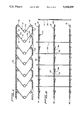
- FIG. 1 is a side elevational view of a portion of a spring assembly embodying the present invention and with certain parts removed;
- FIG. 2 is a plan view of the assembly of FIG. 1 and additionally showing a portion of a border wire;
- FIGS. 3 and 4 are generally similar to FIGS. 1 and 2 but showing a preferred embodiment of the present invention
- FIG. 2 a spring assembly embodying the present invention and including a plurality of generally parallel rows R1, R2 and R3 of springs 10 extending across the assembly, the springs being interconnected by hooks 20 and coils 18 of the upper and lower runs as will be described in further detail below.
- the rows of springs are connected to a border frame shown in FIG. 2 as a border wire 4 which extends around the assembly as a rectangle.
- a plurality of runner wires 30 are secured to the upper runs 12 of the assembly and in the particular embodiment extend lengthwise and are spaced across the assembly.
- the runner wires 30 are connected to the upper runs 12 by means of helical wires 40 which are wrapped or spiralled around the upper runs of the springs.
- the runner wires 30 have a plurality of offset portions 32 extending along portions of the upper runs 12 and being connected thereto by the wraps of the helical wire 40.
- runner wires 30 are also provided across the lower runs 14 of the springs 10 and are connected to them by helical coils 40 as shown in FIG. 1.
- the opposite extremities of the runner wires 30 in both the upper and lower runs of the spring assembly are connected to the border wire 4 in any suitable manner.
- Each of the springs 10 in the preferred embodiment is made from 13 gauge spring wire which has a thickness of approximately 0.092 inches.
- the wire is formed into upper and lower runs 12 and a intermediate run 16 so that the spring has a generally "M" shape or sigma shape.
- On one end of the runs is a hook 20 extending in a generally horizontal plane when the spring is in a vertical plane while on the opposite end of each of the runs is a coil 18 dimensioned to receive a hook 20 as shown in FIGS. 1 and 2.
- the coils 18 each include approximately 2.25 wraps or coils and further the inside diameter of the wraps is preferably 0.480 inches. Also it should be noted from FIG.
- the upper and lower runs 12 and 14 are offset outwardly from the coils 18 to provide sufficient space for accommodating the helical wires 40 which are wrapped about the upper and lower runs 12 and 14 as described above.
- the hooks 20 of the upper and lower runs are offset inwardly from the upper and lower runs respectively so as to be receivable in the coils 18 of the adjacent spring.
- each of the springs 10 includes a coil 22 which in the preferred embodiment has at least 3.25 wraps or coils and an inside diameter of 0.690 inches.
- the hooks 20 are engaged with the loops 18 to form a row of springs which is layed upon a jig.
- the runner wires 30 are then placed across one of the upper or lower runs of the springs 12 or 14, and then the helical coils 40 are spiraled about the run of the row of springs with the coils of the helical wire 40 moving about the run of the springs as well as the offset portions 32 of the runner wires 30.
- the helical wires 40 will be threaded through the loops 34 of the offset portions 32 to ensure that the runner wires 30 will secured in the desired position relative to the springs 12.
- the opposite run of the springs is then provided with runner wires 30 in the said manner as described above.
- FIGS. 3 and 4 there is shown a preferred embodiment of the spring assembly of the present invention which is generally the same as that described above with the exception that the coils 50 at one of the ends of each of the upper and lower runs of the springs 49 are provided with ear portions 52 which project laterally beyond the circular coil wraps 50 as best shown in FIG. 3. Ears 52 provide an aperture for receiving the hook 54 of an adjacent spring as shown in FIGS. 3 and 4.
- the other difference in the preferred embodiment of FIGS. 3 and 4 is that the length 1 of the offset portion of the upper and lower runs 56 and 58 is less than that of the springs 10 in the above described embodiment.
- the spring and spring assembly of the present invention will provide an extremely durable body support that may be incorporated in mattresses or seating units and yet will endure many years of repeated use without breakdown. Moreover while the springs and spring assembly of the present invention presents a novel coil unit for mattresses or seating units, they will still meet industry standards of durability when repeatedly subjected to certain loads over long time periods.
Landscapes
- Mattresses And Other Support Structures For Chairs And Beds (AREA)
- Springs (AREA)
Abstract
Description
Claims (12)
Priority Applications (5)
| Application Number | Priority Date | Filing Date | Title |
|---|---|---|---|
| US07/729,734 US5184809A (en) | 1991-07-15 | 1991-07-15 | Spring assembly for seating and bedding |
| US08/184,776 US5364082A (en) | 1991-07-15 | 1994-01-21 | Spring assembly for seating and bedding |
| US08/336,280 US5431376A (en) | 1991-07-15 | 1994-11-08 | Spring assembly for seating and bedding |
| US08/436,583 US5474283A (en) | 1991-07-15 | 1995-05-08 | Spring assembly for seating and bedding |
| US08/437,605 US5535460A (en) | 1991-07-15 | 1995-05-09 | Spring assembly for seating and bedding |
Applications Claiming Priority (1)
| Application Number | Priority Date | Filing Date | Title |
|---|---|---|---|
| US07/729,734 US5184809A (en) | 1991-07-15 | 1991-07-15 | Spring assembly for seating and bedding |
Related Child Applications (1)
| Application Number | Title | Priority Date | Filing Date |
|---|---|---|---|
| US98376492A Division | 1991-07-15 | 1992-12-01 |
Publications (1)
| Publication Number | Publication Date |
|---|---|
| US5184809A true US5184809A (en) | 1993-02-09 |
Family
ID=24932378
Family Applications (5)
| Application Number | Title | Priority Date | Filing Date |
|---|---|---|---|
| US07/729,734 Expired - Lifetime US5184809A (en) | 1991-07-15 | 1991-07-15 | Spring assembly for seating and bedding |
| US08/184,776 Expired - Lifetime US5364082A (en) | 1991-07-15 | 1994-01-21 | Spring assembly for seating and bedding |
| US08/336,280 Expired - Lifetime US5431376A (en) | 1991-07-15 | 1994-11-08 | Spring assembly for seating and bedding |
| US08/436,583 Expired - Lifetime US5474283A (en) | 1991-07-15 | 1995-05-08 | Spring assembly for seating and bedding |
| US08/437,605 Expired - Lifetime US5535460A (en) | 1991-07-15 | 1995-05-09 | Spring assembly for seating and bedding |
Family Applications After (4)
| Application Number | Title | Priority Date | Filing Date |
|---|---|---|---|
| US08/184,776 Expired - Lifetime US5364082A (en) | 1991-07-15 | 1994-01-21 | Spring assembly for seating and bedding |
| US08/336,280 Expired - Lifetime US5431376A (en) | 1991-07-15 | 1994-11-08 | Spring assembly for seating and bedding |
| US08/436,583 Expired - Lifetime US5474283A (en) | 1991-07-15 | 1995-05-08 | Spring assembly for seating and bedding |
| US08/437,605 Expired - Lifetime US5535460A (en) | 1991-07-15 | 1995-05-09 | Spring assembly for seating and bedding |
Country Status (1)
| Country | Link |
|---|---|
| US (5) | US5184809A (en) |
Cited By (6)
| Publication number | Priority date | Publication date | Assignee | Title |
|---|---|---|---|---|
| US5474283A (en) * | 1991-07-15 | 1995-12-12 | Parma Corporation | Spring assembly for seating and bedding |
| US5524305A (en) * | 1994-11-25 | 1996-06-11 | Parma Corporation | Wire grid for foldable bed with collapsible sinuous springs |
| WO2000004808A1 (en) | 1998-07-23 | 2000-02-03 | Parma Corporation | Foldable bed with collapsible sinuous springs |
| US20060142768A1 (en) * | 2001-12-14 | 2006-06-29 | Paul Kamaljit S | Bone treatment plate assembly |
| EP3363329A1 (en) | 2017-02-15 | 2018-08-22 | John Edward Miller | Foldable, stand-alone mattress with internal spring system |
| US20220325769A1 (en) * | 2021-04-09 | 2022-10-13 | Qing-Rui LIN | Shock isolation cushion |
Families Citing this family (5)
| Publication number | Priority date | Publication date | Assignee | Title |
|---|---|---|---|---|
| US5797101A (en) * | 1996-01-31 | 1998-08-18 | Motorola, Inc. | Radiotelephone subscriber unit having a generic phone number |
| US20060033252A1 (en) * | 2004-08-13 | 2006-02-16 | Elmoselhy Salah A M | Sigma Sigma-springs for suspension systems |
| US8806672B1 (en) | 2012-05-14 | 2014-08-19 | Axess Direct, Inc. | Foldable sofa mattress and method |
| US9015879B1 (en) | 2012-05-14 | 2015-04-28 | Axess Direct, Inc. | Foldable sofa mattress and method |
| US9185991B2 (en) | 2013-12-30 | 2015-11-17 | Axess Direct, Inc. | Uni-directional rigidifier and method |
Citations (7)
| Publication number | Priority date | Publication date | Assignee | Title |
|---|---|---|---|---|
| US457041A (en) * | 1891-08-04 | Bed-bottom | ||
| US811234A (en) * | 1905-08-04 | 1906-01-30 | Roy C Manson | Springwork. |
| US1895429A (en) * | 1930-01-02 | 1933-01-24 | Foster Brothers Mfg Co | Spring construction |
| US1906612A (en) * | 1930-03-21 | 1933-05-02 | Charles D Karr | Spring assembly |
| US4654905A (en) * | 1983-12-08 | 1987-04-07 | Parma Corporation | Body support for bed or seat |
| US4726572A (en) * | 1986-05-16 | 1988-02-23 | Sealy, Incorporated | Spring coil and spring assembly |
| US4811932A (en) * | 1987-07-06 | 1989-03-14 | Parma Corporation | Coil spring mattress core |
Family Cites Families (15)
| Publication number | Priority date | Publication date | Assignee | Title |
|---|---|---|---|---|
| US514898A (en) * | 1894-02-20 | Spring-bed | ||
| US647912A (en) * | 1899-04-24 | 1900-04-17 | George N Phelps | Spring seat or support for furniture, &c. |
| US754120A (en) * | 1902-08-25 | 1904-03-08 | Francis Karr | Spring bed-bottom. |
| US1564601A (en) * | 1923-03-12 | 1925-12-08 | Michael R Mangan | Spring structure |
| GB275484A (en) * | 1927-01-15 | 1927-08-11 | Ewald Thomas | Spring-mattress |
| US1982426A (en) * | 1931-11-23 | 1934-11-27 | Otto L Goethel | Triple lock spring with floating top |
| US2016872A (en) * | 1933-11-29 | 1935-10-08 | Joseph W Droll | Spring structure for mattresses and the like |
| US2291390A (en) * | 1938-05-11 | 1942-07-28 | Kay Mfg Corp | Spring mattress structure |
| US2248093A (en) * | 1938-06-24 | 1941-07-08 | John C Lincoln | Spring seat structure for automobiles |
| US3022521A (en) * | 1960-08-26 | 1962-02-27 | Eclipse Sleep Products Inc | Border stabilizers |
| US3673619A (en) * | 1970-01-07 | 1972-07-04 | Eclipse Sleep Products Inc | Trapezoidal stabilizers for inner spring units |
| US4620336A (en) * | 1982-04-13 | 1986-11-04 | Parma Corporation | Body support for bed or seat |
| US4489450A (en) * | 1982-04-13 | 1984-12-25 | Parma Corporation | Body support for bed or seat |
| US5184809A (en) * | 1991-07-15 | 1993-02-09 | Parma Corporation | Spring assembly for seating and bedding |
| US5257424A (en) * | 1992-04-15 | 1993-11-02 | Rogers Walter C | Foldable bed |
-
1991
- 1991-07-15 US US07/729,734 patent/US5184809A/en not_active Expired - Lifetime
-
1994
- 1994-01-21 US US08/184,776 patent/US5364082A/en not_active Expired - Lifetime
- 1994-11-08 US US08/336,280 patent/US5431376A/en not_active Expired - Lifetime
-
1995
- 1995-05-08 US US08/436,583 patent/US5474283A/en not_active Expired - Lifetime
- 1995-05-09 US US08/437,605 patent/US5535460A/en not_active Expired - Lifetime
Patent Citations (7)
| Publication number | Priority date | Publication date | Assignee | Title |
|---|---|---|---|---|
| US457041A (en) * | 1891-08-04 | Bed-bottom | ||
| US811234A (en) * | 1905-08-04 | 1906-01-30 | Roy C Manson | Springwork. |
| US1895429A (en) * | 1930-01-02 | 1933-01-24 | Foster Brothers Mfg Co | Spring construction |
| US1906612A (en) * | 1930-03-21 | 1933-05-02 | Charles D Karr | Spring assembly |
| US4654905A (en) * | 1983-12-08 | 1987-04-07 | Parma Corporation | Body support for bed or seat |
| US4726572A (en) * | 1986-05-16 | 1988-02-23 | Sealy, Incorporated | Spring coil and spring assembly |
| US4811932A (en) * | 1987-07-06 | 1989-03-14 | Parma Corporation | Coil spring mattress core |
Cited By (15)
| Publication number | Priority date | Publication date | Assignee | Title |
|---|---|---|---|---|
| US5535460A (en) * | 1991-07-15 | 1996-07-16 | Parma Corporation | Spring assembly for seating and bedding |
| US5474283A (en) * | 1991-07-15 | 1995-12-12 | Parma Corporation | Spring assembly for seating and bedding |
| US5642536A (en) * | 1994-11-25 | 1997-07-01 | Parma Corporation | Foldable bed with collapsible sinuous springs and pivotable leg |
| US5540418A (en) * | 1994-11-25 | 1996-07-30 | Parma Corporation | Foldbale bed with collapsible sinuous springs |
| US5539940A (en) * | 1994-11-25 | 1996-07-30 | Parma Corporation | Foldable sofa bed with collapsible sinuous springs |
| US5539944A (en) * | 1994-11-25 | 1996-07-30 | Parma Corporation | Foldable bed with collapsible sinuous springs |
| US5524305A (en) * | 1994-11-25 | 1996-06-11 | Parma Corporation | Wire grid for foldable bed with collapsible sinuous springs |
| US5655240A (en) * | 1994-11-25 | 1997-08-12 | Parma Corporation | Mattress with reinforcing wire truss or strap |
| WO2000004808A1 (en) | 1998-07-23 | 2000-02-03 | Parma Corporation | Foldable bed with collapsible sinuous springs |
| US20060142768A1 (en) * | 2001-12-14 | 2006-06-29 | Paul Kamaljit S | Bone treatment plate assembly |
| US8128668B2 (en) * | 2001-12-14 | 2012-03-06 | Paul Kamaljit S | Bone treatment plate assembly |
| US8470006B2 (en) | 2003-10-22 | 2013-06-25 | Kamaljit S. Paul | Bone repair systems |
| EP3363329A1 (en) | 2017-02-15 | 2018-08-22 | John Edward Miller | Foldable, stand-alone mattress with internal spring system |
| US20220325769A1 (en) * | 2021-04-09 | 2022-10-13 | Qing-Rui LIN | Shock isolation cushion |
| US11644078B2 (en) * | 2021-04-09 | 2023-05-09 | Royal Su | Shock isolation cushion |
Also Published As
| Publication number | Publication date |
|---|---|
| US5431376A (en) | 1995-07-11 |
| US5535460A (en) | 1996-07-16 |
| US5364082A (en) | 1994-11-15 |
| US5474283A (en) | 1995-12-12 |
Similar Documents
| Publication | Publication Date | Title |
|---|---|---|
| US8490232B2 (en) | Spring core having border wire with generally rectangular cross-section | |
| US5184809A (en) | Spring assembly for seating and bedding | |
| US4160544A (en) | Small diameter, single cone coil spring for use in a box spring assembly | |
| US3911511A (en) | Spring assembly | |
| US4960267A (en) | Edge-reinforced spring bedding product | |
| US4555097A (en) | Combination round coil spring and rectangular torsion coil spring assembly | |
| US7044454B2 (en) | Mattress inner spring assembly | |
| US3636574A (en) | Supporting means for a mattress, cushion and the like | |
| JPH04502265A (en) | internal spring | |
| US4095297A (en) | Coil spring assembly | |
| US5924150A (en) | Mattress edge support spring and handle structure | |
| US5062172A (en) | Bedding mattress spring assembly having border edge support | |
| US4112528A (en) | Box spring assembly and small diameter single cone coil spring for use in that assembly | |
| US3774248A (en) | Coil spring assembly | |
| US9044102B2 (en) | Spring core having border wire with generally rectangular cross-section | |
| US3916464A (en) | Pre-stressed spring matrix | |
| US5562274A (en) | Formed wire mattress assembly | |
| US4136410A (en) | Spring deck for seating structures | |
| US4101992A (en) | Spring assembly with reinforcement | |
| US3426371A (en) | Spring assembly | |
| US4790519A (en) | Borderwire hinge clip | |
| US4172589A (en) | Cushion support element | |
| EP0697183B1 (en) | Double structure spring mattress | |
| US4124201A (en) | Knockdown spring unit | |
| US2515177A (en) | Spring cushion for upholstered furniture |
Legal Events
| Date | Code | Title | Description |
|---|---|---|---|
| AS | Assignment |
Owner name: MCDONALD, JACK, NORTH CAROLINA Free format text: ASSIGNMENT OF ASSIGNORS INTEREST.;ASSIGNOR:MILLER, JOHN E.;REEL/FRAME:006372/0466 Effective date: 19910701 |
|
| STCF | Information on status: patent grant |
Free format text: PATENTED CASE |
|
| AS | Assignment |
Owner name: PARMA CORPORATION, NORTH CAROLINA Free format text: ASSIGNMENT OF ASSIGNORS INTEREST;ASSIGNOR:MILLER, JOHN E.;REEL/FRAME:006526/0908 Effective date: 19910701 |
|
| FEPP | Fee payment procedure |
Free format text: PAYOR NUMBER ASSIGNED (ORIGINAL EVENT CODE: ASPN); ENTITY STATUS OF PATENT OWNER: SMALL ENTITY |
|
| FPAY | Fee payment |
Year of fee payment: 4 |
|
| FEPP | Fee payment procedure |
Free format text: PAYER NUMBER DE-ASSIGNED (ORIGINAL EVENT CODE: RMPN); ENTITY STATUS OF PATENT OWNER: SMALL ENTITY Free format text: PAYOR NUMBER ASSIGNED (ORIGINAL EVENT CODE: ASPN); ENTITY STATUS OF PATENT OWNER: SMALL ENTITY |
|
| FPAY | Fee payment |
Year of fee payment: 8 |
|
| FPAY | Fee payment |
Year of fee payment: 12 |
|
| AS | Assignment |
Owner name: MILLER, JOHN E., MISSISSIPPI Free format text: ASSIGNMENT OF ASSIGNORS INTEREST;ASSIGNOR:PARMA CORPORATION;REEL/FRAME:021590/0116 Effective date: 20080624 |