EP0704245A1 - Pulverizing method with a horizontal mill and horizontal mill - Google Patents
Pulverizing method with a horizontal mill and horizontal mill Download PDFInfo
- Publication number
- EP0704245A1 EP0704245A1 EP95111607A EP95111607A EP0704245A1 EP 0704245 A1 EP0704245 A1 EP 0704245A1 EP 95111607 A EP95111607 A EP 95111607A EP 95111607 A EP95111607 A EP 95111607A EP 0704245 A1 EP0704245 A1 EP 0704245A1
- Authority
- EP
- European Patent Office
- Prior art keywords
- pulverizing
- media
- diameter
- sleeve
- rotational speed
- Prior art date
- Legal status (The legal status is an assumption and is not a legal conclusion. Google has not performed a legal analysis and makes no representation as to the accuracy of the status listed.)
- Granted
Links
Images


Classifications
-
- B—PERFORMING OPERATIONS; TRANSPORTING
- B02—CRUSHING, PULVERISING, OR DISINTEGRATING; PREPARATORY TREATMENT OF GRAIN FOR MILLING
- B02C—CRUSHING, PULVERISING, OR DISINTEGRATING IN GENERAL; MILLING GRAIN
- B02C17/00—Disintegrating by tumbling mills, i.e. mills having a container charged with the material to be disintegrated with or without special disintegrating members such as pebbles or balls
- B02C17/16—Mills in which a fixed container houses stirring means tumbling the charge
- B02C17/166—Mills in which a fixed container houses stirring means tumbling the charge of the annular gap type
Definitions
- the present invention relates to a ultra-fine pulverizing method for obtaining ultra fine particles having a size of several microns or less, which are needed as a high strength concrete, a high performance catalyst or the like.
- the gap S is small ( S/R ⁇ 0.50 )
- S/R the agitating effect attained by the agitating shaft 02 would degrade.
- a frictional wear of the pulverizing media is large.
- the frictional wear rate of the pulverizing media is in proportion to a rotational speed of the mill and a specific surface area of the pulverizing media, the more the acceleration and the smaller the pulverizing media, the more the frictional wear rate will become as shown in Fig. 5.
- a damage rate of the pulverizing media is high.
- the mill power is in proportion to the rotational speed and the amount of heat generated in the mill is in proportion to the mill power. Accordingly, in case of the high rotational speed, the temperature of the pulverized material becomes high. In many cases, the elevated temperature would be a factor of the degradation of the quality of the pulverized material or the hindrance against the upgrading the performance.
- An object of the present invention is to enhance pulverizing characteristics and to reduce a power consumption while suppressing damages/wears of pulverizing media in a horizontal mill for ultra-fine pulverization by using the pulverizing media (balls) and using a space between an inner sleeve and an outer sleeve which are rotated relative to each other as a pulverizing chamber.
- a pulverizing method with a horizontal mill in which pulverizing media are received in a space having an annular cross section between a substantially horizontal outer sleeve having an inner surface on which a plurality of agitating vanes are mounted and an inner sleeve having an outer surface on which a plurality of vanes are mounted, said inner sleeve being coaxial with said outer sleeve, and in which at least one of said outer and inner sleeves is rotated to thereby pulverize a material to be fed into the space having the annular cross section, said pulverizing method being characterized in that:
- a horizontal mill comprising: a substantially horizontal outer sleeve having an inner surface on which a plurality of agitating vanes are mounted; an inner sleeve having an outer surface on which a plurality of agitating vanes are mounted, said inner sleeve being coaxial with said outer sleeve; pulverizing media received in a space having annular cross section between said outer sleeve and said inner sleeve; and means for rotating at least one of said outer sleeve and said inner sleeve, for pulverizing a material to be fed into the space having the annular cross section, said horizontal mill being characterized in that:
- reference numeral 1 denotes an outer sleeve
- numeral 2 denotes an inner sleeve
- reference characters 3a and 3b denote motors
- characters 4a and 4b denote speed reducers
- characters 5a, 5b, 6a and 6b denote gears
- numeral 7 denotes flanges
- numeral 8 denotes bearings
- numeral 9 denotes fastening members
- numeral 10 denotes a hollow rotary shaft
- numeral 11 denotes grand packings
- numeral 12 denotes a slurry feed pipe
- numeral 13 denotes a slurry feed hole
- numeral 14 denotes a pulverizing chamber
- numeral 15 denotes a pulverizing medium
- numeral 16 denotes a porous plate
- numeral 17 denotes slits
- numeral 18 denotes a reservoir chamber
- numeral 19 denotes a discharge port
- numeral 20 denotes
- the mill shown in Fig. 1 is of a mutual rotational type in which the outer sleeve 1 and the inner sleeve 2 are rotated in opposite directions and the material to be pulverized is fed from the slurry feed pipe in the form of the slurry and is discharged from the discharge pipe 21.
- the mill shown in Fig. 2 is of an inner sleeve independent rotational type in which the material to be pulverized is fed from the pulverized material feed inlet 24 in the form of powder and is discharged from the discharge pipe 21.
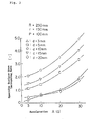
- a pulverizing energy E of a single pulverizing medium having a diameter d, to be given to the pulverized material is given as follows: E ⁇ (in proportion to) ⁇ x d 3 x v 2 ⁇ ⁇ x d 3 x A where ⁇ is the media density, v is the media rotational speed and A is the maximum acceleration.
- a pulverizing method using a large diameter medium at a low rotational speed as in the method according to the present invention may give a much greater pulverizing energy than that in the conventional case of the small diameter media at the high rotational speed.
- the pulverization characteristics of the conventional mill are shown as 1.0 when the diameter d is 3 mm and the acceleration A is 20G.
- Fig. 5 shows the test result which compares the wear conditions of the pulverizing media when the silica stone had been pulverized continuously for 50 hours.
- the media wear rate of the ordinate represents the ratio of weights of the media before and after the test.
- the wear could be reduced.
- a plurality of agitating vanes are provided on the inner surface of the outer sleeve and the outer surface of the inner sleeve.
- the axial interval (pitch) between the agitating vanes largely affects the pulverizing characteristics and the drivability of the mill.
- the present inventors have found from a number of tests that it was possible to classify the pitches P according to the ratio with the pulverizing media diameter d as shown in Fig. 7 and the optimum range was 3 ⁇ P/d ⁇ 60 in case of the large diameter media of 5 to 15 mm at the low rotational speed of 3G or less.
- a volume of the pulverizing chamber 14 (hatched portion) in Fig. 8 was small. In this case, it was sufficient to use a small weight of the media in order to obtain the same media filling rate (media filling height h/pulverizing chamber height H) (see Fig. 9). Since the mill power consumption was increased in accordance with the increase of the media weight, there was a large effect with the small weight of the media. Also, the pulverization is effected at the outer annular portion where the maximum media rotational speed may be obtained and the pulverizing efficiency is enhanced as described later.
- the curve I represents the change of the pulverizing media weight. Since the more S/R (the less the inner sleeve), the more the volume of the pulverizing chamber would become. Accordingly, the weight of the pulverizing media was increased. As a result, the mill power consumption was increased in accordance with the increase of S/R as indicated by the curve II.
Abstract
Description
- The present invention relates to a ultra-fine pulverizing method for obtaining ultra fine particles having a size of several microns or less, which are needed as a high strength concrete, a high performance catalyst or the like.
- A recent technology is disclosed in Japanese Patent Examined Publication No. Hei 5-87307 entitled "Centrifugal Processing Method and Apparatus". The concept of that technology is a vertical mill as shown in Fig. 15 in which an
agitating shaft 02 is provided within a hollow rotor 01 and pulverizingmedia 03 are disposed in a gap S between theshaft 02 and the rotor 01. Then, under the condition that the material M to be processed is present in the gap S, the hollow rotor 01 is rotated and at the same time, theagitating shaft 02 is rotated in the opposite direction to that of the rotor 01, thereby pulverizing the material M to be processed. According to the publication, the rotational speed is adjusted so that an acceleration exceeding 1G is applied to the pulverizingmedia 03, and it is preferable to select the pulverizing region in the range of 10G to 200G. - Also, according to the publication, it is preferable that when an inner radius of the hollow rotor 01 is represented by R, the above-described gap S meets the relation,


shaft 02 would degrade. - Conventionally, there is a theory prerequisite that "it is preferable to use the high rotational speed and the small size pulverizing media". Therefore, it is proposed to use the high speed rotation of 10G to 200G as mentioned above. Also, it is general to use the pulverizing media having a small diameter of 3 mm or less.
- However, this high rotational speed and small diameter media type mill suffers from the following problems.
- Since the frictional wear rate of the pulverizing media is in proportion to a rotational speed of the mill and a specific surface area of the pulverizing media, the more the acceleration and the smaller the pulverizing media, the more the frictional wear rate will become as shown in Fig. 5.
- The more the diameter of the pulverizing media, the more the pressure yield strength of the pulverizing media will become. Therefore, in case of the small diameter media, the damage rate of the pulverizing media is high.
- The mill power is in proportion to the rotational speed and the amount of heat generated in the mill is in proportion to the mill power. Accordingly, in case of the high rotational speed, the temperature of the pulverized material becomes high. In many cases, the elevated temperature would be a factor of the degradation of the quality of the pulverized material or the hindrance against the upgrading the performance.
- An object of the present invention is to enhance pulverizing characteristics and to reduce a power consumption while suppressing damages/wears of pulverizing media in a horizontal mill for ultra-fine pulverization by using the pulverizing media (balls) and using a space between an inner sleeve and an outer sleeve which are rotated relative to each other as a pulverizing chamber.
- In order to attain this and other objects, according to the present invention, there is provided a pulverizing method with a horizontal mill, in which pulverizing media are received in a space having an annular cross section between a substantially horizontal outer sleeve having an inner surface on which a plurality of agitating vanes are mounted and an inner sleeve having an outer surface on which a plurality of vanes are mounted, said inner sleeve being coaxial with said outer sleeve, and in which at least one of said outer and inner sleeves is rotated to thereby pulverize a material to be fed into the space having the annular cross section, said pulverizing method being characterized in that:
- (a) at least one of said inner sleeve and said outer sleeve is rotated at such a rotational speed that a maximum acceleration to be applied to the pulverizing media does not exceed three times of a gravitational acceleration;
- (b) a diameter of the pulverizing media is in the range of 5 to 15 mm;
- (c) an interval between the inner surface of said outer sleeve and the outer surface of said inner sleeve is not smaller than three times of a diameter of the pulverizing media;
- (d) an axial interval between the agitating vanes of each of said inner and outer sleeves is in the range of three to sixty times of the diameter of the pulverizing media; and
- (e) a ratio of an inner diameter of said outer sleeve to an outer diameter of said inner sleeve is not smaller than 0.5.
- According to the method of the invention, it is possible to enjoy the following effects.
- (a) Since at least one of said inner sleeve and said outer sleeve is rotated at such a rotational speed that a maximum acceleration to be applied to the pulverizing media does not exceed three times of a gravitational acceleration, the wear of the pulverizing media may be suppressed.
- (b) Since a diameter of the pulverizing media is in the range of 5 to 15 mm, the degradation of the pulverizing force due to the low rotational speed may be recovered.
- (c) Since an interval between the inner surface of said outer sleeve and the outer surface of said inner sleeve is not smaller than three times of a diameter of the pulverizing media, the driving failure (abnormally high power) by a bridge phenomenon of the pulverizing media may be prevented.
- (d) Since an axial interval between the agitating vanes of each of said inner and outer sleeves is in the range of three to sixty times of the diameter of the pulverizing media, the bridge phenomenon of the pulverizing media and the pulverizing power transmission failure may be prevented.
- (e) Since a ratio of an inner diameter of said outer sleeve to an outer diameter of said inner sleeve is not smaller than 0.5, the media filling weight is small at the same media filling rate and the power consumption may be reduced.
- Also, in order to attain the above-described and other objects, according to another aspect of the invention, there is provided a horizontal mill comprising:
a substantially horizontal outer sleeve having an inner surface on which a plurality of agitating vanes are mounted;
an inner sleeve having an outer surface on which a plurality of agitating vanes are mounted, said inner sleeve being coaxial with said outer sleeve;
pulverizing media received in a space having annular cross section between said outer sleeve and said inner sleeve; and
means for rotating at least one of said outer sleeve and said inner sleeve, for pulverizing a material to be fed into the space having the annular cross section, said horizontal mill being characterized in that: - (a) a diameter of the pulverizing media is in the range of 5 to 15 mm;
- (b) an interval between the inner surface of said outer sleeve and the outer surface of said inner sleeve is not smaller than three times of a diameter of the pulverizing media;
- (c) an axial interval between the agitating vanes of each of said inner and outer sleeves is in the range of three to sixty times of the diameter of the pulverizing media; and
- (d) a ratio of an inner diameter of said outer sleeve to an outer diameter of said inner sleeve is not smaller than 0.5.
- According to this mill, it is possible to effectively carry out the pulverizing method of the present invention.
- In the accompanying drawings:
- Fig. 1 is a longitudinal sectional view showing an example of a horizontal mill according to the present invention, for embodying a method of the invention;
- Fig. 2 is a longitudinal sectional view showing another example of a horizontal mill according to the present invention, for embodying a method of the invention;
- Fig. 3 is a graph showing an experimental result concerning a relationship between an acceleration and a pulverizing media diameter and pulverizing characteristics;
- Fig. 4 is a graph showing an experimental result concerning a relationship between the pulverizing media diameter and a pulverization efficiency;
- Fig. 5 is a graph showing an experimental result concerning a relationship between the acceleration, the pulverizing media diameter, and a wear status of the pulverizing media;
- Fig. 6 is a graph showing an experimental result concerning a relationship between an interval between an inner sleeve, an outer sleeve, a size of the pulverizing media, and the mill power;
- Fig. 7 is a graph showing an experimental result concerning a relationship between an axial interval of the agitating vanes, a size of the pulverizing media, and the mill power;
- Fig. 8 is a view showing a relationship between a dimensional ratio of the inner and outer sleeves and a volume of a pulverizing chamber;
- Fig. 9 is a view illustrating the media filling efficiency;
- Fig. 10 is a graph showing an experimental result concerning a relationship between the dimensional ratio of the inner and outer sleeve, the pulverizing media weight, the mill power consumption and the pulverizing power source unit;
- Fig. 11 is a graph showing a relation between the dimensional ratio of the inner and outer sleeves and the rotational speed of the pulverizing media;
- Fig. 12 is a view exemplifying the experimental result of the continuous pulverization of calcium carbonate;
- Fig. 13 is a view exemplifying the experimental result in comparison with the mill outlet temperature when the silica stone is wet pulverized;
- Fig. 14 is a view exemplifying the experimental result of generation of the mechanochemistry of an iron system catalyst; and
- Fig. 15 is a longitudinal sectional view showing an example of a conventional mill.
- The present invention will now be described with reference to the accompanying drawings.
- In Figs. 1 and 2 showing horizontal mills embodying a method of the present invention,
reference numeral 1 denotes an outer sleeve, numeral 2 denotes an inner sleeve,reference characters 3a and 3b denote motors,characters 4a and 4b denote speed reducers,characters numerals outer sleeve 1 and theinner sleeve 2 are rotated in opposite directions and the material to be pulverized is fed from the slurry feed pipe in the form of the slurry and is discharged from the discharge pipe 21. Also, the mill shown in Fig. 2 is of an inner sleeve independent rotational type in which the material to be pulverized is fed from the pulverizedmaterial feed inlet 24 in the form of powder and is discharged from the discharge pipe 21. - A pulverizing energy E of a single pulverizing medium having a diameter d, to be given to the pulverized material, is given as follows:

- Accordingly, in comparison with the case of d=10 mm and A=3G and the case of d=3 mm and A=20G, the ratio of the pulverized energy is (10³x3)/(3³x20)=5.6. A pulverizing method using a large diameter medium at a low rotational speed as in the method according to the present invention may give a much greater pulverizing energy than that in the conventional case of the small diameter media at the high rotational speed.
- The pulverizing characteristics are shown in Fig. 3, in which the horizontal mills (the
outer sleeve 1 having the inner radius R=250 mm kept constant) was used, and the silica stone pulverizing test was conducted by changing the acceleration A and the pulverizing media diameter d under the condition that the outer radius r of theinner sleeve 2 was 150 mm (
- Also, in order to confirm the characteristics at the low rotational speed, the pulverizing test for FRP which was a kind of plastics was conducted under the condition A=1.5G (constant). The result is shown in Fig. 4. Fig. 4 shows a relationship between the pulverizing efficiency (1µm or less when a constant energy was applied) and the pulverizing media diameter d. It was understood from the experimental result that it was possible to obtain high pulverizing characteristics by using the media having the large diameter of d=5 to 15 mm.
- On the other hand, the frictional wear rate of the pulverizing media could be considerably reduced by using the low rotational speed. Fig. 5 shows the test result which compares the wear conditions of the pulverizing media when the silica stone had been pulverized continuously for 50 hours. The media wear rate of the ordinate represents the ratio of weights of the media before and after the test. As was apparent from this, when the large diameter media were used at the low rotational speed, the wear could be reduced. For example, in comparison with the case of the conventional mill (A=20G and d=3 mm), the wear amount could be reduced to about one tenth in case of A=1.5G and d=10 mm.
- When the gap S between the inner and outer sleeves was too small, a bridge phenomenon of the pulverizing media was generated and its motion was prevented so that the power became abnormally high. As a result, the mill would be tripped. The present inventors have found from a number of tests that the relation shown in Fig. 6 was established between S/d, and the mill power and if the interval between the inner sleeve and the outer sleeve in which three media were interposed, i.e.,

- In the horizontal mills embodying the present invention, a plurality of agitating vanes are provided on the inner surface of the outer sleeve and the outer surface of the inner sleeve. The axial interval (pitch) between the agitating vanes largely affects the pulverizing characteristics and the drivability of the mill. The present inventors have found from a number of tests that it was possible to classify the pitches P according to the ratio with the pulverizing media diameter d as shown in Fig. 7 and the optimum range was


- If the inner sleeve having the large outer diameter was used while the inner diameter of the outer sleeve was kept constant; that is, r/R was large and S/R was small, a volume of the pulverizing chamber 14 (hatched portion) in Fig. 8 was small. In this case, it was sufficient to use a small weight of the media in order to obtain the same media filling rate (media filling height h/pulverizing chamber height H) (see Fig. 9). Since the mill power consumption was increased in accordance with the increase of the media weight, there was a large effect with the small weight of the media. Also, the pulverization is effected at the outer annular portion where the maximum media rotational speed may be obtained and the pulverizing efficiency is enhanced as described later.
- Fig. 10 shows the test result in which the ratio S/R was changed from 0.1 to 0.9 under the condition of the media filling rate of 85%, A=1.5G and d=10 mm (any of which was kept constant). The curve I represents the change of the pulverizing media weight. Since the more S/R (the less the inner sleeve), the more the volume of the pulverizing chamber would become. Accordingly, the weight of the pulverizing media was increased. As a result, the mill power consumption was increased in accordance with the increase of S/R as indicated by the curve II. Also, the reason why the power was abruptly increased at the ratio S/R of 0.1 was that S=250mmx0.1=25mm, i.e.,


- On the other hand, the curve III shows the pulverizing power source unit ratio (power consumption per one ton in case of pulverizing for the same particle size). It is understood from the curve that the range where the pulverization is possible with the least power is


- It is assumed that the reason why the pulverizing processing ability is small in the case where S/R is large is that, as shown by the rate gradient curve in Fig. 11(b), the rotational speed of the pulverizing media in the vicinity of the inner sleeve is very small and the rotational speed has almost no function to contribute to the pulverization. In contrast, according to the present invention, since


- Fig. 12 shows a continuous pulverization result with calcium carbonate under the condition of the ranges specified according to the method of the present invention, i.e., A=1.5G, d=10mm,


- The following effects may be obtained according to the pulverizing method and the pulverizing mill of the invention.
- 1) Since the temperature elevation of the pulverized material within the mill is small in case of the upgraded capacity, it is possible to obtain a large capacity mill.
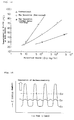
This is based upon the fact that the large cooling area of the inner sleeve may be kept by using the large diameter inner sleeve, the filling amount is reduced even if the filling rate of the pulverizing media is kept constant, and further the pulverizing power is reduced by optimizing the interval S between the inner and outer sleeves and the axial interval P of the agitating vanes. Fig. 13 shows a test result of the mill outlet slurry temperature when the silica stone was pulverized according to the wet milling method of the invention in comparison with the conventional method. It is understood that the present invention is suitably applicable to the large capacity system. Actually, the 4t/h silica stone ultra-fine pulverizing mill which is said to be the largest in the world is well operated. - 2) A mechanochemical effect may readily be found out in the pulverization.
This effect is based upon the fact that the pulverizing media having a large diameter of from 5 to 15 mm is used. The "mechanochemistry" means a phenomenon in which a mechanical energy is applied to a solid material by the pulverizing effect so that a lattice defect is increased, a size of crystalline particles is reduces, and amorphous property is generated. At this time, in many cases, a reaction property, adsorption, catalyst activity or the like is considerably enhanced. Recently, by utilizing these characteristics, the additional value and quality of the pulverized material have been enhanced.
Fig. 14 shows an experimental result of the mechanochemistry of the iron system catalyst. It has been found that even if the same energy (Ext) is applied, the mechanochemistry does not occur in the small size media mill (indicated by E₂ in Fig. 14) and the mechanochemistry occurs only in the large size media mill ( indicated by E₁ in Fig. 14) having the media diameter of 5 to 15 mm. The reason for finding the mechanochemistry would be that the mechanochemistry occurs only under the conditions that the critical energy Ecr is present and the instantaneous energy E to be given from the pulverizing media to the pulverized material is larger than Ecr. Namely, the mechanochemistry is more readily generated in the case where a large energy is given by the large size media even if the number of the media is small than the case the large energy is given by the small media. - 3) As described above, the present invention is based upon the opposite concept to the conventional prerequisite theory that the small media and high rotational speeds are preferable for the ultra-fine pulverization. According to the invention, the large media and the low rotational speed are used. As a result, the present invention may be practically applied to a high capacity ultra-super pulverizing mill of 4t/h to which the conventional method would be applied with difficulty and the present invention may be successfully applied to a highly additional valuable powder structure by the mechanochemistry.
Claims (2)
- A pulverizing method with a horizontal mill, in which pulverizing media (15) are received in a space (14) having an annular cross section between a substantially horizontal outer sleeve (1) having an inner surface on which a plurality of agitating vanes (22) are mounted and an inner sleeve (2) having an outer surface on which a plurality of agitating vanes (23) are mounted, said inner sleeve (2) being coaxial with said outer sleeve (1), and in which at least one of said outer and inner sleeves (1, 2) is rotated to thereby pulverize a material to be fed into the space (14) having the annular cross section, said pulverizing method being characterized in that:(a) at least one of said inner sleeve (2) and said outer sleeve (1) is rotated at such a rotational speed that a maximum acceleration to be applied to the pulverizing media (15) does not exceed three times of a gravitational acceleration;(b) a diameter of the pulverizing media (15) is in the range of 5 to 15 mm;(c) an interval between the inner surface of said outer sleeve (1) and the outer surface of said inner sleeve (2) is not smaller than three times of a diameter of the pulverizing media (15);(d) an axial interval (P) between the agitating vanes (22, 23) of each of said inner and outer sleeves (2, 1) is in the range of three to sixty times of the diameter of the pulverizing media; and(e) a ratio of an inner diameter (R) of said outer sleeve (1) to an outer diameter (r) of said inner sleeve (2) is not smaller than 0.5.
- A horizontal mill comprising:
a substantially horizontal outer sleeve (1) having an inner surface on which a plurality of agitating vanes (22) are mounted;
an inner sleeve (2) having an outer surface on which a plurality of agitating vanes (23) are mounted, said inner sleeve (2) being coaxial with said outer sleeve (1);
pulverizing media (15) received in a space (14) having annular cross section between said outer sleeve (1) and said inner sleeve (2); and
means (3, 4, 5) for rotating at least one of said outer sleeve (1) and said inner sleeve (2), for pulverizing a material to be fed into the space (14) having the annular cross section, said horizontal mill being characterized in that:(a) a diameter of the pulverizing media (15) is in the range of 5 to 15 mm;(b) an interval (S) between the inner surface of said outer sleeve (1) and the outer surface of said inner sleeve (2)is not smaller than three times of a diameter of the pulverizing media (15);(c) an axial interval (P) between the agitating vanes (22, 23) of each of said inner and outer sleeves (2, 1) is in the range of three to sixty times of the diameter of the pulverizing media (15); and(d) a ratio of an inner diameter (R) of said outer sleeve (1) to an outer diameter (r) of said inner sleeve (2) is not smaller than 0.5.
Applications Claiming Priority (3)
| Application Number | Priority Date | Filing Date | Title |
|---|---|---|---|
| JP232994/94 | 1994-09-28 | ||
| JP23299494 | 1994-09-28 | ||
| JP23299494A JP3174694B2 (en) | 1994-09-28 | 1994-09-28 | Grinding method with horizontal mill |
Publications (2)
| Publication Number | Publication Date |
|---|---|
| EP0704245A1 true EP0704245A1 (en) | 1996-04-03 |
| EP0704245B1 EP0704245B1 (en) | 1999-10-06 |
Family
ID=16948141
Family Applications (1)
| Application Number | Title | Priority Date | Filing Date |
|---|---|---|---|
| EP95111607A Expired - Lifetime EP0704245B1 (en) | 1994-09-28 | 1995-07-24 | Pulverizing method with a horizontal mill and horizontal mill |
Country Status (8)
| Country | Link |
|---|---|
| US (1) | US5544818A (en) |
| EP (1) | EP0704245B1 (en) |
| JP (1) | JP3174694B2 (en) |
| AU (1) | AU669835B2 (en) |
| DE (1) | DE69512596T2 (en) |
| ES (1) | ES2136776T3 (en) |
| FI (1) | FI110847B (en) |
| ZA (1) | ZA956072B (en) |
Cited By (10)
| Publication number | Priority date | Publication date | Assignee | Title |
|---|---|---|---|---|
| WO2000047325A1 (en) * | 1999-02-10 | 2000-08-17 | Leschonski K | Pinned disk mill |
| EP1358940A1 (en) * | 2002-04-30 | 2003-11-05 | Dainippon Ink And Chemicals, Inc. | Dispersion apparatus and dispersion method |
| WO2010101483A1 (en) * | 2009-03-06 | 2010-09-10 | Progressive Ip Limited | Improvements in & relating to the comminution of waste & other materials |
| WO2011035451A2 (en) | 2009-09-23 | 2011-03-31 | Hamza Delic Mesic | Assembly of interconnected mineral pulverising mills |
| WO2011130805A1 (en) * | 2010-04-22 | 2011-10-27 | A New Way Of Living Pty Ltd | Material treatment and apparatus |
| CN104668029A (en) * | 2015-02-12 | 2015-06-03 | 钱国臣 | Chemical material grinding device and using method thereof |
| CN104668031A (en) * | 2015-02-12 | 2015-06-03 | 吴扬华 | Powder preparation device for manufacturing ceramics and application method of powder preparation device |
| CN106732976A (en) * | 2017-01-16 | 2017-05-31 | 成都佳欣诚信科技有限公司 | A kind of device for producing fine powder coating |
| CN108905947A (en) * | 2018-04-13 | 2018-11-30 | 长沙宁湖机械设备有限公司 | A kind of stagewise activation equipment |
| CN108993681A (en) * | 2018-04-13 | 2018-12-14 | 长沙宁湖机械设备有限公司 | A kind of vertical activation equipment |
Families Citing this family (10)
| Publication number | Priority date | Publication date | Assignee | Title |
|---|---|---|---|---|
| KR19990073270A (en) * | 1999-06-29 | 1999-10-05 | 정상옥 | A ball mill |
| KR20030025649A (en) * | 2001-09-21 | 2003-03-29 | 조현정 | Media agitated grinding device for nanosize grinding and dispersing |
| KR100643654B1 (en) * | 2005-10-20 | 2006-11-10 | 태성개발(주) | Manufacturing method of aggregate and its apparatus for recycling construction waste material |
| KR100643655B1 (en) * | 2005-10-20 | 2006-11-10 | 태성개발(주) | Manufacturing method of aggregate and its apparatus for recycling construction waste material |
| JP5173238B2 (en) * | 2007-04-13 | 2013-04-03 | 日本コークス工業株式会社 | Crushing method |
| JP2009028687A (en) * | 2007-07-30 | 2009-02-12 | Chuo Kakoki Kk | Method of mechanochemistry treatment |
| JP5921172B2 (en) * | 2011-12-09 | 2016-05-24 | アシザワ・ファインテック株式会社 | Horizontal dry crusher |
| CN110369054A (en) * | 2019-08-23 | 2019-10-25 | 扬州自丰机械制造有限公司 | A kind of vertical ball grinder |
| CN112337590B (en) * | 2020-10-22 | 2022-02-08 | 西藏昌都高争建材股份有限公司 | Ball loading device for cement production |
| CN112169924A (en) * | 2020-10-23 | 2021-01-05 | 张家妹 | Wet overflow ball mill for ore dressing |
Citations (5)
| Publication number | Priority date | Publication date | Assignee | Title |
|---|---|---|---|---|
| US3202364A (en) * | 1961-11-03 | 1965-08-24 | Holderbank Cement | Method of and apparatus for grinding material |
| FR2510908A1 (en) * | 1981-08-04 | 1983-02-11 | Euro Machines | Ball grinder for fine suspensions - employs water-cooled rotor and stator with balls of 1 mm. dia. |
| EP0219740A2 (en) * | 1985-08-27 | 1987-04-29 | Reimbold & Strick GmbH & Co. KG | Annular-gap ball mill |
| EP0476189A1 (en) * | 1988-11-02 | 1992-03-25 | Akademie der Wissenschaften der DDR | Equipment for continuous wet grinding of solid materials |
| JPH0587307A (en) | 1991-09-30 | 1993-04-06 | Hitachi Ltd | Method and device for controlling main steam temperature of boiler |
Family Cites Families (8)
| Publication number | Priority date | Publication date | Assignee | Title |
|---|---|---|---|---|
| DE2047244B2 (en) * | 1970-09-25 | 1981-03-26 | Gebrüder Netzsch, Maschinenfabrik GmbH & Co, 95100 Selb | Agitator mill for continuous fine grinding and dispersing of flowable grist |
| CH618893A5 (en) * | 1977-04-29 | 1980-08-29 | Buehler Ag Geb | |
| SU686759A1 (en) * | 1978-03-28 | 1979-09-28 | Dolgopolov Vyacheslav | Grinding mill |
| US4206879A (en) * | 1978-08-10 | 1980-06-10 | Gebrueder Buehler Ag | Agitator mill |
| US4651935A (en) * | 1984-10-19 | 1987-03-24 | Morehouse Industries, Inc. | Horizontal media mill |
| US5246173A (en) * | 1989-10-04 | 1993-09-21 | Hoechst Aktiengesellschaft | Vibrating stirred ball mill |
| DE4128074C2 (en) * | 1991-08-23 | 1995-06-29 | Omya Gmbh | Agitator ball mill |
| CH688849A5 (en) * | 1993-02-25 | 1998-04-30 | Buehler Ag | Agitator mill. |
-
1994
- 1994-09-28 JP JP23299494A patent/JP3174694B2/en not_active Expired - Fee Related
-
1995
- 1995-07-20 ZA ZA956072A patent/ZA956072B/en unknown
- 1995-07-21 US US08/505,636 patent/US5544818A/en not_active Expired - Fee Related
- 1995-07-21 AU AU27130/95A patent/AU669835B2/en not_active Ceased
- 1995-07-24 DE DE69512596T patent/DE69512596T2/en not_active Expired - Fee Related
- 1995-07-24 ES ES95111607T patent/ES2136776T3/en not_active Expired - Lifetime
- 1995-07-24 EP EP95111607A patent/EP0704245B1/en not_active Expired - Lifetime
- 1995-09-06 FI FI954168A patent/FI110847B/en active
Patent Citations (5)
| Publication number | Priority date | Publication date | Assignee | Title |
|---|---|---|---|---|
| US3202364A (en) * | 1961-11-03 | 1965-08-24 | Holderbank Cement | Method of and apparatus for grinding material |
| FR2510908A1 (en) * | 1981-08-04 | 1983-02-11 | Euro Machines | Ball grinder for fine suspensions - employs water-cooled rotor and stator with balls of 1 mm. dia. |
| EP0219740A2 (en) * | 1985-08-27 | 1987-04-29 | Reimbold & Strick GmbH & Co. KG | Annular-gap ball mill |
| EP0476189A1 (en) * | 1988-11-02 | 1992-03-25 | Akademie der Wissenschaften der DDR | Equipment for continuous wet grinding of solid materials |
| JPH0587307A (en) | 1991-09-30 | 1993-04-06 | Hitachi Ltd | Method and device for controlling main steam temperature of boiler |
Cited By (17)
| Publication number | Priority date | Publication date | Assignee | Title |
|---|---|---|---|---|
| WO2000047325A1 (en) * | 1999-02-10 | 2000-08-17 | Leschonski K | Pinned disk mill |
| EP1358940A1 (en) * | 2002-04-30 | 2003-11-05 | Dainippon Ink And Chemicals, Inc. | Dispersion apparatus and dispersion method |
| CN100512938C (en) * | 2002-04-30 | 2009-07-15 | 大日本油墨化学工业株式会社 | Dispersing apparatus and dispersing method |
| WO2010101483A1 (en) * | 2009-03-06 | 2010-09-10 | Progressive Ip Limited | Improvements in & relating to the comminution of waste & other materials |
| US8910891B2 (en) | 2009-03-06 | 2014-12-16 | Progressive Ip Ltd. | Comminution of waste and other materials |
| WO2011035451A2 (en) | 2009-09-23 | 2011-03-31 | Hamza Delic Mesic | Assembly of interconnected mineral pulverising mills |
| US9421549B2 (en) | 2010-04-22 | 2016-08-23 | A New Way Of Living Pty Ltd | Material treatment and apparatus |
| WO2011130805A1 (en) * | 2010-04-22 | 2011-10-27 | A New Way Of Living Pty Ltd | Material treatment and apparatus |
| AU2011242420C1 (en) * | 2010-04-22 | 2020-09-03 | A New Way Of Living Pty Ltd | Material treatment and apparatus |
| AU2011242420B2 (en) * | 2010-04-22 | 2016-04-14 | A New Way Of Living Pty Ltd | Material treatment and apparatus |
| CN104668031A (en) * | 2015-02-12 | 2015-06-03 | 吴扬华 | Powder preparation device for manufacturing ceramics and application method of powder preparation device |
| CN104668029A (en) * | 2015-02-12 | 2015-06-03 | 钱国臣 | Chemical material grinding device and using method thereof |
| CN106732976A (en) * | 2017-01-16 | 2017-05-31 | 成都佳欣诚信科技有限公司 | A kind of device for producing fine powder coating |
| CN108905947A (en) * | 2018-04-13 | 2018-11-30 | 长沙宁湖机械设备有限公司 | A kind of stagewise activation equipment |
| CN108993681A (en) * | 2018-04-13 | 2018-12-14 | 长沙宁湖机械设备有限公司 | A kind of vertical activation equipment |
| CN108993681B (en) * | 2018-04-13 | 2020-11-27 | 嘉兴极客旅游用品有限公司 | Vertical activation machine |
| CN108905947B (en) * | 2018-04-13 | 2020-12-18 | 浙江昌新生物纤维股份有限公司 | Hierarchical formula activation machine |
Also Published As
| Publication number | Publication date |
|---|---|
| AU2713095A (en) | 1996-04-18 |
| ZA956072B (en) | 1996-02-27 |
| US5544818A (en) | 1996-08-13 |
| DE69512596T2 (en) | 2000-03-30 |
| FI954168A0 (en) | 1995-09-06 |
| AU669835B2 (en) | 1996-06-20 |
| JPH0889832A (en) | 1996-04-09 |
| ES2136776T3 (en) | 1999-12-01 |
| JP3174694B2 (en) | 2001-06-11 |
| DE69512596D1 (en) | 1999-11-11 |
| EP0704245B1 (en) | 1999-10-06 |
| FI110847B (en) | 2003-04-15 |
| FI954168A (en) | 1996-03-29 |
Similar Documents
| Publication | Publication Date | Title |
|---|---|---|
| EP0704245B1 (en) | Pulverizing method with a horizontal mill and horizontal mill | |
| EP0775526B1 (en) | Mechanical grinding apparatus | |
| US4721258A (en) | Roll-and-race pulverizer with rotating throat | |
| EP0513770B1 (en) | Crushing apparatus and crushing method | |
| US5806772A (en) | Conical gyratory grinding and crushing apparatus | |
| US4687145A (en) | Roll-and-race pulverizer with rotating throat | |
| US7963470B2 (en) | Discharge from grinding mills | |
| JPH0710357B2 (en) | Scavenging type crusher | |
| CN1041998C (en) | Method of and apparatus for continouslly production of pulverized flowing material | |
| JP3273394B2 (en) | Mechanical grinding equipment | |
| JP3900311B2 (en) | Mechanical crusher | |
| US5083713A (en) | Process for disintegrating silica fine powder | |
| US20120132736A1 (en) | Silicon metal grinding machine | |
| CN1209082A (en) | Energy-efficient grinding rolls for coal pulverizers | |
| JP4120981B2 (en) | Mechanical crusher | |
| JP3241260B2 (en) | Horizontal ultra-fine grinding mill | |
| JPH03217249A (en) | Vertical type grinder | |
| US3469795A (en) | Material reduction mill | |
| Harris et al. | Grinding mill operation and scale-up: theory and equations | |
| JPH0667490B2 (en) | Horizontal crusher | |
| JPH0732884B2 (en) | Horizontal crusher | |
| JPH0880446A (en) | Vertical pulverizer | |
| JPS58196855A (en) | Shaft type finely crushing machine | |
| JP2727220B2 (en) | Fine powder crushing method | |
| JP2787967B2 (en) | Centrifugal flow crusher |
Legal Events
| Date | Code | Title | Description |
|---|---|---|---|
| PUAI | Public reference made under article 153(3) epc to a published international application that has entered the european phase |
Free format text: ORIGINAL CODE: 0009012 |
|
| 17P | Request for examination filed |
Effective date: 19950821 |
|
| AK | Designated contracting states |
Kind code of ref document: A1 Designated state(s): DE ES |
|
| GRAG | Despatch of communication of intention to grant |
Free format text: ORIGINAL CODE: EPIDOS AGRA |
|
| 17Q | First examination report despatched |
Effective date: 19981020 |
|
| GRAG | Despatch of communication of intention to grant |
Free format text: ORIGINAL CODE: EPIDOS AGRA |
|
| GRAH | Despatch of communication of intention to grant a patent |
Free format text: ORIGINAL CODE: EPIDOS IGRA |
|
| GRAH | Despatch of communication of intention to grant a patent |
Free format text: ORIGINAL CODE: EPIDOS IGRA |
|
| GRAA | (expected) grant |
Free format text: ORIGINAL CODE: 0009210 |
|
| AK | Designated contracting states |
Kind code of ref document: B1 Designated state(s): DE ES |
|
| REF | Corresponds to: |
Ref document number: 69512596 Country of ref document: DE Date of ref document: 19991111 |
|
| REG | Reference to a national code |
Ref country code: ES Ref legal event code: FG2A Ref document number: 2136776 Country of ref document: ES Kind code of ref document: T3 |
|
| PLBE | No opposition filed within time limit |
Free format text: ORIGINAL CODE: 0009261 |
|
| STAA | Information on the status of an ep patent application or granted ep patent |
Free format text: STATUS: NO OPPOSITION FILED WITHIN TIME LIMIT |
|
| 26N | No opposition filed | ||
| PGFP | Annual fee paid to national office [announced via postgrant information from national office to epo] |
Ref country code: DE Payment date: 20030731 Year of fee payment: 9 |
|
| PGFP | Annual fee paid to national office [announced via postgrant information from national office to epo] |
Ref country code: ES Payment date: 20030813 Year of fee payment: 9 |
|
| PG25 | Lapsed in a contracting state [announced via postgrant information from national office to epo] |
Ref country code: ES Free format text: LAPSE BECAUSE OF NON-PAYMENT OF DUE FEES Effective date: 20040726 |
|
| PG25 | Lapsed in a contracting state [announced via postgrant information from national office to epo] |
Ref country code: DE Free format text: LAPSE BECAUSE OF NON-PAYMENT OF DUE FEES Effective date: 20050201 |
|
| REG | Reference to a national code |
Ref country code: ES Ref legal event code: FD2A Effective date: 20040726 |