EP0703882B1 - Verfahrem zum anbringen eines oxidationsschutz auf bremsscheiben aus kohlenstoff enthaltendem verbundmaterial - Google Patents
Verfahrem zum anbringen eines oxidationsschutz auf bremsscheiben aus kohlenstoff enthaltendem verbundmaterial Download PDFInfo
- Publication number
- EP0703882B1 EP0703882B1 EP95916708A EP95916708A EP0703882B1 EP 0703882 B1 EP0703882 B1 EP 0703882B1 EP 95916708 A EP95916708 A EP 95916708A EP 95916708 A EP95916708 A EP 95916708A EP 0703882 B1 EP0703882 B1 EP 0703882B1
- Authority
- EP
- European Patent Office
- Prior art keywords
- process according
- composition
- internal
- protection
- brake disk
- Prior art date
- Legal status (The legal status is an assumption and is not a legal conclusion. Google has not performed a legal analysis and makes no representation as to the accuracy of the status listed.)
- Expired - Lifetime
Links
- 239000011248 coating agent Substances 0.000 title claims abstract description 19
- 238000000576 coating method Methods 0.000 title claims abstract description 19
- 238000000034 method Methods 0.000 title claims description 61
- OKTJSMMVPCPJKN-UHFFFAOYSA-N Carbon Chemical compound [C] OKTJSMMVPCPJKN-UHFFFAOYSA-N 0.000 title claims description 36
- 229910052799 carbon Inorganic materials 0.000 title claims description 34
- 239000002131 composite material Substances 0.000 title claims description 23
- 230000003078 antioxidant effect Effects 0.000 title abstract 3
- 239000000203 mixture Substances 0.000 claims abstract description 105
- 238000005470 impregnation Methods 0.000 claims abstract description 64
- 230000035515 penetration Effects 0.000 claims abstract description 11
- 239000011148 porous material Substances 0.000 claims abstract description 11
- 230000004224 protection Effects 0.000 claims description 119
- 239000011521 glass Substances 0.000 claims description 49
- 230000008569 process Effects 0.000 claims description 48
- 239000002243 precursor Substances 0.000 claims description 44
- XLOMVQKBTHCTTD-UHFFFAOYSA-N Zinc monoxide Chemical compound [Zn]=O XLOMVQKBTHCTTD-UHFFFAOYSA-N 0.000 claims description 42
- 239000000243 solution Substances 0.000 claims description 40
- 238000007254 oxidation reaction Methods 0.000 claims description 36
- 230000003647 oxidation Effects 0.000 claims description 33
- 239000000463 material Substances 0.000 claims description 26
- 239000011787 zinc oxide Substances 0.000 claims description 21
- 230000015572 biosynthetic process Effects 0.000 claims description 17
- 229910019142 PO4 Inorganic materials 0.000 claims description 16
- 235000021317 phosphate Nutrition 0.000 claims description 16
- 230000007797 corrosion Effects 0.000 claims description 15
- 238000005260 corrosion Methods 0.000 claims description 15
- 238000010438 heat treatment Methods 0.000 claims description 13
- 239000007788 liquid Substances 0.000 claims description 12
- NBIIXXVUZAFLBC-UHFFFAOYSA-K phosphate Chemical compound [O-]P([O-])([O-])=O NBIIXXVUZAFLBC-UHFFFAOYSA-K 0.000 claims description 12
- 239000010452 phosphate Substances 0.000 claims description 12
- DLYUQMMRRRQYAE-UHFFFAOYSA-N tetraphosphorus decaoxide Chemical compound O1P(O2)(=O)OP3(=O)OP1(=O)OP2(=O)O3 DLYUQMMRRRQYAE-UHFFFAOYSA-N 0.000 claims description 12
- 239000010410 layer Substances 0.000 claims description 10
- 229920001971 elastomer Polymers 0.000 claims description 9
- 230000000873 masking effect Effects 0.000 claims description 9
- 239000000725 suspension Substances 0.000 claims description 9
- GWEVSGVZZGPLCZ-UHFFFAOYSA-N Titan oxide Chemical compound O=[Ti]=O GWEVSGVZZGPLCZ-UHFFFAOYSA-N 0.000 claims description 8
- 239000007864 aqueous solution Substances 0.000 claims description 8
- WMWLMWRWZQELOS-UHFFFAOYSA-N bismuth(iii) oxide Chemical compound O=[Bi]O[Bi]=O WMWLMWRWZQELOS-UHFFFAOYSA-N 0.000 claims description 8
- 239000000470 constituent Substances 0.000 claims description 8
- XLYOFNOQVPJJNP-UHFFFAOYSA-N water Substances O XLYOFNOQVPJJNP-UHFFFAOYSA-N 0.000 claims description 8
- 239000011241 protective layer Substances 0.000 claims description 6
- ONDPHDOFVYQSGI-UHFFFAOYSA-N zinc nitrate Chemical compound [Zn+2].[O-][N+]([O-])=O.[O-][N+]([O-])=O ONDPHDOFVYQSGI-UHFFFAOYSA-N 0.000 claims description 6
- PNEYBMLMFCGWSK-UHFFFAOYSA-N aluminium oxide Inorganic materials [O-2].[O-2].[O-2].[Al+3].[Al+3] PNEYBMLMFCGWSK-UHFFFAOYSA-N 0.000 claims description 5
- 239000011324 bead Substances 0.000 claims description 5
- 238000005507 spraying Methods 0.000 claims description 5
- 229910011255 B2O3 Inorganic materials 0.000 claims description 4
- FUJCRWPEOMXPAD-UHFFFAOYSA-N Li2O Inorganic materials [Li+].[Li+].[O-2] FUJCRWPEOMXPAD-UHFFFAOYSA-N 0.000 claims description 4
- KKCBUQHMOMHUOY-UHFFFAOYSA-N Na2O Inorganic materials [O-2].[Na+].[Na+] KKCBUQHMOMHUOY-UHFFFAOYSA-N 0.000 claims description 4
- 229920000388 Polyphosphate Polymers 0.000 claims description 4
- 229910000272 alkali metal oxide Inorganic materials 0.000 claims description 4
- 229910052593 corundum Inorganic materials 0.000 claims description 4
- XUCJHNOBJLKZNU-UHFFFAOYSA-M dilithium;hydroxide Chemical compound [Li+].[Li+].[OH-] XUCJHNOBJLKZNU-UHFFFAOYSA-M 0.000 claims description 4
- 238000007496 glass forming Methods 0.000 claims description 4
- 150000003013 phosphoric acid derivatives Chemical class 0.000 claims description 4
- 239000001205 polyphosphate Substances 0.000 claims description 4
- 235000011176 polyphosphates Nutrition 0.000 claims description 4
- 239000000126 substance Substances 0.000 claims description 4
- 229910001845 yogo sapphire Inorganic materials 0.000 claims description 4
- 238000000151 deposition Methods 0.000 claims description 3
- 238000003754 machining Methods 0.000 claims description 3
- NWONKYPBYAMBJT-UHFFFAOYSA-L zinc sulfate Chemical compound [Zn+2].[O-]S([O-])(=O)=O NWONKYPBYAMBJT-UHFFFAOYSA-L 0.000 claims description 3
- 229960001763 zinc sulfate Drugs 0.000 claims description 3
- 229910000368 zinc sulfate Inorganic materials 0.000 claims description 3
- MOMKYJPSVWEWPM-UHFFFAOYSA-N 4-(chloromethyl)-2-(4-methylphenyl)-1,3-thiazole Chemical compound C1=CC(C)=CC=C1C1=NC(CCl)=CS1 MOMKYJPSVWEWPM-UHFFFAOYSA-N 0.000 claims description 2
- VYPSYNLAJGMNEJ-UHFFFAOYSA-N Silicium dioxide Chemical compound O=[Si]=O VYPSYNLAJGMNEJ-UHFFFAOYSA-N 0.000 claims description 2
- 238000004891 communication Methods 0.000 claims description 2
- AZSFNUJOCKMOGB-UHFFFAOYSA-K cyclotriphosphate(3-) Chemical compound [O-]P1(=O)OP([O-])(=O)OP([O-])(=O)O1 AZSFNUJOCKMOGB-UHFFFAOYSA-K 0.000 claims description 2
- 235000019983 sodium metaphosphate Nutrition 0.000 claims description 2
- 150000003751 zinc Chemical class 0.000 claims description 2
- 230000002378 acidificating effect Effects 0.000 claims 1
- 239000008119 colloidal silica Substances 0.000 claims 1
- 230000001419 dependent effect Effects 0.000 claims 1
- 239000002344 surface layer Substances 0.000 claims 1
- 230000003064 anti-oxidating effect Effects 0.000 description 29
- 238000012360 testing method Methods 0.000 description 25
- 238000007789 sealing Methods 0.000 description 13
- CREMABGTGYGIQB-UHFFFAOYSA-N carbon carbon Chemical compound C.C CREMABGTGYGIQB-UHFFFAOYSA-N 0.000 description 10
- 239000011203 carbon fibre reinforced carbon Substances 0.000 description 10
- SCVFZCLFOSHCOH-UHFFFAOYSA-M potassium acetate Chemical compound [K+].CC([O-])=O SCVFZCLFOSHCOH-UHFFFAOYSA-M 0.000 description 10
- 239000011159 matrix material Substances 0.000 description 9
- 238000001035 drying Methods 0.000 description 8
- 229910052708 sodium Inorganic materials 0.000 description 7
- 235000002639 sodium chloride Nutrition 0.000 description 7
- NBIIXXVUZAFLBC-UHFFFAOYSA-N Phosphoric acid Chemical compound OP(O)(O)=O NBIIXXVUZAFLBC-UHFFFAOYSA-N 0.000 description 6
- 150000003839 salts Chemical class 0.000 description 6
- 238000007711 solidification Methods 0.000 description 6
- 230000008023 solidification Effects 0.000 description 6
- 239000000835 fiber Substances 0.000 description 5
- 235000012245 magnesium oxide Nutrition 0.000 description 5
- 235000011056 potassium acetate Nutrition 0.000 description 5
- 230000002787 reinforcement Effects 0.000 description 5
- 239000011734 sodium Substances 0.000 description 5
- 241001639412 Verres Species 0.000 description 4
- 239000003054 catalyst Substances 0.000 description 4
- 239000000919 ceramic Substances 0.000 description 4
- 229910052751 metal Inorganic materials 0.000 description 4
- 239000002184 metal Substances 0.000 description 4
- 230000036961 partial effect Effects 0.000 description 4
- LWIHDJKSTIGBAC-UHFFFAOYSA-K potassium phosphate Substances [K+].[K+].[K+].[O-]P([O-])([O-])=O LWIHDJKSTIGBAC-UHFFFAOYSA-K 0.000 description 4
- 239000000047 product Substances 0.000 description 4
- 229910018072 Al 2 O 3 Inorganic materials 0.000 description 3
- DGAQECJNVWCQMB-PUAWFVPOSA-M Ilexoside XXIX Chemical compound C[C@@H]1CC[C@@]2(CC[C@@]3(C(=CC[C@H]4[C@]3(CC[C@@H]5[C@@]4(CC[C@@H](C5(C)C)OS(=O)(=O)[O-])C)C)[C@@H]2[C@]1(C)O)C)C(=O)O[C@H]6[C@@H]([C@H]([C@@H]([C@H](O6)CO)O)O)O.[Na+] DGAQECJNVWCQMB-PUAWFVPOSA-M 0.000 description 3
- 229910000147 aluminium phosphate Inorganic materials 0.000 description 3
- 230000003197 catalytic effect Effects 0.000 description 3
- 230000006870 function Effects 0.000 description 3
- 229910052739 hydrogen Inorganic materials 0.000 description 3
- 230000016507 interphase Effects 0.000 description 3
- CHWRSCGUEQEHOH-UHFFFAOYSA-N potassium oxide Chemical compound [O-2].[K+].[K+] CHWRSCGUEQEHOH-UHFFFAOYSA-N 0.000 description 3
- 230000002829 reductive effect Effects 0.000 description 3
- 239000007787 solid Substances 0.000 description 3
- QGZKDVFQNNGYKY-UHFFFAOYSA-N Ammonia Chemical compound N QGZKDVFQNNGYKY-UHFFFAOYSA-N 0.000 description 2
- 229910015902 Bi 2 O 3 Inorganic materials 0.000 description 2
- 229920000049 Carbon (fiber) Polymers 0.000 description 2
- XEEYBQQBJWHFJM-UHFFFAOYSA-N Iron Chemical compound [Fe] XEEYBQQBJWHFJM-UHFFFAOYSA-N 0.000 description 2
- 229910018068 Li 2 O Inorganic materials 0.000 description 2
- PXHVJJICTQNCMI-UHFFFAOYSA-N Nickel Chemical compound [Ni] PXHVJJICTQNCMI-UHFFFAOYSA-N 0.000 description 2
- 229910010413 TiO 2 Inorganic materials 0.000 description 2
- QVGXLLKOCUKJST-UHFFFAOYSA-N atomic oxygen Chemical compound [O] QVGXLLKOCUKJST-UHFFFAOYSA-N 0.000 description 2
- 230000008901 benefit Effects 0.000 description 2
- 229910052796 boron Inorganic materials 0.000 description 2
- 230000001680 brushing effect Effects 0.000 description 2
- 239000004917 carbon fiber Substances 0.000 description 2
- 238000010668 complexation reaction Methods 0.000 description 2
- 230000007547 defect Effects 0.000 description 2
- 230000008034 disappearance Effects 0.000 description 2
- 238000004090 dissolution Methods 0.000 description 2
- 230000008030 elimination Effects 0.000 description 2
- 238000003379 elimination reaction Methods 0.000 description 2
- 239000012530 fluid Substances 0.000 description 2
- 229910002804 graphite Inorganic materials 0.000 description 2
- 239000010439 graphite Substances 0.000 description 2
- 230000008595 infiltration Effects 0.000 description 2
- 238000001764 infiltration Methods 0.000 description 2
- 230000002045 lasting effect Effects 0.000 description 2
- 238000004519 manufacturing process Methods 0.000 description 2
- 230000005226 mechanical processes and functions Effects 0.000 description 2
- 239000003607 modifier Substances 0.000 description 2
- 235000019796 monopotassium phosphate Nutrition 0.000 description 2
- 229910000402 monopotassium phosphate Inorganic materials 0.000 description 2
- 230000007935 neutral effect Effects 0.000 description 2
- 238000005121 nitriding Methods 0.000 description 2
- 229910052760 oxygen Inorganic materials 0.000 description 2
- 239000001301 oxygen Substances 0.000 description 2
- 235000011837 pasties Nutrition 0.000 description 2
- PJNZPQUBCPKICU-UHFFFAOYSA-N phosphoric acid;potassium Chemical compound [K].OP(O)(O)=O PJNZPQUBCPKICU-UHFFFAOYSA-N 0.000 description 2
- 238000007750 plasma spraying Methods 0.000 description 2
- 239000004033 plastic Substances 0.000 description 2
- 229920001343 polytetrafluoroethylene Polymers 0.000 description 2
- 239000004810 polytetrafluoroethylene Substances 0.000 description 2
- 235000011009 potassium phosphates Nutrition 0.000 description 2
- 239000002244 precipitate Substances 0.000 description 2
- 239000011253 protective coating Substances 0.000 description 2
- 230000001681 protective effect Effects 0.000 description 2
- 239000002296 pyrolytic carbon Substances 0.000 description 2
- 239000001488 sodium phosphate Substances 0.000 description 2
- 235000011008 sodium phosphates Nutrition 0.000 description 2
- 125000006850 spacer group Chemical group 0.000 description 2
- 239000003381 stabilizer Substances 0.000 description 2
- 230000009466 transformation Effects 0.000 description 2
- 230000007704 transition Effects 0.000 description 2
- 229910000838 Al alloy Inorganic materials 0.000 description 1
- 239000004254 Ammonium phosphate Substances 0.000 description 1
- RYGMFSIKBFXOCR-UHFFFAOYSA-N Copper Chemical compound [Cu] RYGMFSIKBFXOCR-UHFFFAOYSA-N 0.000 description 1
- UFHFLCQGNIYNRP-UHFFFAOYSA-N Hydrogen Chemical compound [H][H] UFHFLCQGNIYNRP-UHFFFAOYSA-N 0.000 description 1
- WHXSMMKQMYFTQS-UHFFFAOYSA-N Lithium Chemical compound [Li] WHXSMMKQMYFTQS-UHFFFAOYSA-N 0.000 description 1
- 241001460678 Napo <wasp> Species 0.000 description 1
- FAPWRFPIFSIZLT-UHFFFAOYSA-M Sodium chloride Chemical compound [Na+].[Cl-] FAPWRFPIFSIZLT-UHFFFAOYSA-M 0.000 description 1
- 230000006978 adaptation Effects 0.000 description 1
- 229910052782 aluminium Inorganic materials 0.000 description 1
- XAGFODPZIPBFFR-UHFFFAOYSA-N aluminium Chemical compound [Al] XAGFODPZIPBFFR-UHFFFAOYSA-N 0.000 description 1
- 229910021529 ammonia Inorganic materials 0.000 description 1
- 229910000148 ammonium phosphate Inorganic materials 0.000 description 1
- 235000019289 ammonium phosphates Nutrition 0.000 description 1
- 230000004888 barrier function Effects 0.000 description 1
- 239000002585 base Substances 0.000 description 1
- 229910052797 bismuth Inorganic materials 0.000 description 1
- JCXGWMGPZLAOME-UHFFFAOYSA-N bismuth atom Chemical compound [Bi] JCXGWMGPZLAOME-UHFFFAOYSA-N 0.000 description 1
- 229910052810 boron oxide Inorganic materials 0.000 description 1
- 150000001768 cations Chemical class 0.000 description 1
- 230000008859 change Effects 0.000 description 1
- 238000005229 chemical vapour deposition Methods 0.000 description 1
- 239000011247 coating layer Substances 0.000 description 1
- 229910017052 cobalt Inorganic materials 0.000 description 1
- 239000010941 cobalt Substances 0.000 description 1
- GUTLYIVDDKVIGB-UHFFFAOYSA-N cobalt atom Chemical compound [Co] GUTLYIVDDKVIGB-UHFFFAOYSA-N 0.000 description 1
- 230000000295 complement effect Effects 0.000 description 1
- 238000001816 cooling Methods 0.000 description 1
- 229910052802 copper Inorganic materials 0.000 description 1
- 239000010949 copper Substances 0.000 description 1
- 238000000280 densification Methods 0.000 description 1
- 230000001627 detrimental effect Effects 0.000 description 1
- 238000004031 devitrification Methods 0.000 description 1
- MNNHAPBLZZVQHP-UHFFFAOYSA-N diammonium hydrogen phosphate Chemical compound [NH4+].[NH4+].OP([O-])([O-])=O MNNHAPBLZZVQHP-UHFFFAOYSA-N 0.000 description 1
- RGPUVZXXZFNFBF-UHFFFAOYSA-K diphosphonooxyalumanyl dihydrogen phosphate Chemical compound [Al+3].OP(O)([O-])=O.OP(O)([O-])=O.OP(O)([O-])=O RGPUVZXXZFNFBF-UHFFFAOYSA-K 0.000 description 1
- 239000013013 elastic material Substances 0.000 description 1
- 239000000806 elastomer Substances 0.000 description 1
- 239000004744 fabric Substances 0.000 description 1
- 230000009477 glass transition Effects 0.000 description 1
- PCHJSUWPFVWCPO-UHFFFAOYSA-N gold Chemical compound [Au] PCHJSUWPFVWCPO-UHFFFAOYSA-N 0.000 description 1
- 229910052737 gold Inorganic materials 0.000 description 1
- 239000010931 gold Substances 0.000 description 1
- 238000000227 grinding Methods 0.000 description 1
- 239000001257 hydrogen Substances 0.000 description 1
- 238000007654 immersion Methods 0.000 description 1
- 230000006872 improvement Effects 0.000 description 1
- 238000009434 installation Methods 0.000 description 1
- 229910052742 iron Inorganic materials 0.000 description 1
- 229910001947 lithium oxide Inorganic materials 0.000 description 1
- AXZKOIWUVFPNLO-UHFFFAOYSA-N magnesium;oxygen(2-) Chemical class [O-2].[Mg+2] AXZKOIWUVFPNLO-UHFFFAOYSA-N 0.000 description 1
- 238000012423 maintenance Methods 0.000 description 1
- 238000005259 measurement Methods 0.000 description 1
- 239000000155 melt Substances 0.000 description 1
- 125000005341 metaphosphate group Chemical group 0.000 description 1
- VNWKTOKETHGBQD-UHFFFAOYSA-N methane Chemical compound C VNWKTOKETHGBQD-UHFFFAOYSA-N 0.000 description 1
- 238000000465 moulding Methods 0.000 description 1
- 238000010068 moulding (rubber) Methods 0.000 description 1
- 229910052759 nickel Inorganic materials 0.000 description 1
- 150000004767 nitrides Chemical class 0.000 description 1
- MOWNZPNSYMGTMD-UHFFFAOYSA-N oxidoboron Chemical class O=[B] MOWNZPNSYMGTMD-UHFFFAOYSA-N 0.000 description 1
- SOQBVABWOPYFQZ-UHFFFAOYSA-N oxygen(2-);titanium(4+) Chemical class [O-2].[O-2].[Ti+4] SOQBVABWOPYFQZ-UHFFFAOYSA-N 0.000 description 1
- 239000002245 particle Substances 0.000 description 1
- 230000037361 pathway Effects 0.000 description 1
- -1 polytetrafluoroethylene Polymers 0.000 description 1
- 229910001950 potassium oxide Inorganic materials 0.000 description 1
- 230000002028 premature Effects 0.000 description 1
- 238000002360 preparation method Methods 0.000 description 1
- 238000011084 recovery Methods 0.000 description 1
- 239000011819 refractory material Substances 0.000 description 1
- 239000011347 resin Substances 0.000 description 1
- 229920005989 resin Polymers 0.000 description 1
- 230000000717 retained effect Effects 0.000 description 1
- 230000035945 sensitivity Effects 0.000 description 1
- 230000035939 shock Effects 0.000 description 1
- 229910052710 silicon Inorganic materials 0.000 description 1
- 239000010703 silicon Substances 0.000 description 1
- 239000011780 sodium chloride Substances 0.000 description 1
- UGTZMIPZNRIWHX-UHFFFAOYSA-K sodium trimetaphosphate Chemical compound [Na+].[Na+].[Na+].[O-]P1(=O)OP([O-])(=O)OP([O-])(=O)O1 UGTZMIPZNRIWHX-UHFFFAOYSA-K 0.000 description 1
- 238000003892 spreading Methods 0.000 description 1
- 230000007480 spreading Effects 0.000 description 1
- OGIDPMRJRNCKJF-UHFFFAOYSA-N titanium oxide Inorganic materials [Ti]=O OGIDPMRJRNCKJF-UHFFFAOYSA-N 0.000 description 1
- LEONUFNNVUYDNQ-UHFFFAOYSA-N vanadium atom Chemical compound [V] LEONUFNNVUYDNQ-UHFFFAOYSA-N 0.000 description 1
- 229910001935 vanadium oxide Inorganic materials 0.000 description 1
- 229910052725 zinc Inorganic materials 0.000 description 1
- 239000011701 zinc Substances 0.000 description 1
- LRXTYHSAJDENHV-UHFFFAOYSA-H zinc phosphate Chemical compound [Zn+2].[Zn+2].[Zn+2].[O-]P([O-])([O-])=O.[O-]P([O-])([O-])=O LRXTYHSAJDENHV-UHFFFAOYSA-H 0.000 description 1
- 229910000165 zinc phosphate Inorganic materials 0.000 description 1
Images


Classifications
-
- C—CHEMISTRY; METALLURGY
- C04—CEMENTS; CONCRETE; ARTIFICIAL STONE; CERAMICS; REFRACTORIES
- C04B—LIME, MAGNESIA; SLAG; CEMENTS; COMPOSITIONS THEREOF, e.g. MORTARS, CONCRETE OR LIKE BUILDING MATERIALS; ARTIFICIAL STONE; CERAMICS; REFRACTORIES; TREATMENT OF NATURAL STONE
- C04B41/00—After-treatment of mortars, concrete, artificial stone or ceramics; Treatment of natural stone
- C04B41/009—After-treatment of mortars, concrete, artificial stone or ceramics; Treatment of natural stone characterised by the material treated
-
- B—PERFORMING OPERATIONS; TRANSPORTING
- B05—SPRAYING OR ATOMISING IN GENERAL; APPLYING FLUENT MATERIALS TO SURFACES, IN GENERAL
- B05D—PROCESSES FOR APPLYING FLUENT MATERIALS TO SURFACES, IN GENERAL
- B05D1/00—Processes for applying liquids or other fluent materials
- B05D1/18—Processes for applying liquids or other fluent materials performed by dipping
-
- B—PERFORMING OPERATIONS; TRANSPORTING
- B05—SPRAYING OR ATOMISING IN GENERAL; APPLYING FLUENT MATERIALS TO SURFACES, IN GENERAL
- B05D—PROCESSES FOR APPLYING FLUENT MATERIALS TO SURFACES, IN GENERAL
- B05D1/00—Processes for applying liquids or other fluent materials
- B05D1/32—Processes for applying liquids or other fluent materials using means for protecting parts of a surface not to be coated, e.g. using stencils, resists
-
- B—PERFORMING OPERATIONS; TRANSPORTING
- B05—SPRAYING OR ATOMISING IN GENERAL; APPLYING FLUENT MATERIALS TO SURFACES, IN GENERAL
- B05D—PROCESSES FOR APPLYING FLUENT MATERIALS TO SURFACES, IN GENERAL
- B05D3/00—Pretreatment of surfaces to which liquids or other fluent materials are to be applied; After-treatment of applied coatings, e.g. intermediate treating of an applied coating preparatory to subsequent applications of liquids or other fluent materials
- B05D3/04—Pretreatment of surfaces to which liquids or other fluent materials are to be applied; After-treatment of applied coatings, e.g. intermediate treating of an applied coating preparatory to subsequent applications of liquids or other fluent materials by exposure to gases
- B05D3/0493—Pretreatment of surfaces to which liquids or other fluent materials are to be applied; After-treatment of applied coatings, e.g. intermediate treating of an applied coating preparatory to subsequent applications of liquids or other fluent materials by exposure to gases using vacuum
-
- C—CHEMISTRY; METALLURGY
- C04—CEMENTS; CONCRETE; ARTIFICIAL STONE; CERAMICS; REFRACTORIES
- C04B—LIME, MAGNESIA; SLAG; CEMENTS; COMPOSITIONS THEREOF, e.g. MORTARS, CONCRETE OR LIKE BUILDING MATERIALS; ARTIFICIAL STONE; CERAMICS; REFRACTORIES; TREATMENT OF NATURAL STONE
- C04B41/00—After-treatment of mortars, concrete, artificial stone or ceramics; Treatment of natural stone
- C04B41/45—Coating or impregnating, e.g. injection in masonry, partial coating of green or fired ceramics, organic coating compositions for adhering together two concrete elements
- C04B41/4505—Coating or impregnating, e.g. injection in masonry, partial coating of green or fired ceramics, organic coating compositions for adhering together two concrete elements characterised by the method of application
- C04B41/4515—Coating or impregnating, e.g. injection in masonry, partial coating of green or fired ceramics, organic coating compositions for adhering together two concrete elements characterised by the method of application application under vacuum or reduced pressure
-
- C—CHEMISTRY; METALLURGY
- C04—CEMENTS; CONCRETE; ARTIFICIAL STONE; CERAMICS; REFRACTORIES
- C04B—LIME, MAGNESIA; SLAG; CEMENTS; COMPOSITIONS THEREOF, e.g. MORTARS, CONCRETE OR LIKE BUILDING MATERIALS; ARTIFICIAL STONE; CERAMICS; REFRACTORIES; TREATMENT OF NATURAL STONE
- C04B41/00—After-treatment of mortars, concrete, artificial stone or ceramics; Treatment of natural stone
- C04B41/45—Coating or impregnating, e.g. injection in masonry, partial coating of green or fired ceramics, organic coating compositions for adhering together two concrete elements
- C04B41/4505—Coating or impregnating, e.g. injection in masonry, partial coating of green or fired ceramics, organic coating compositions for adhering together two concrete elements characterised by the method of application
- C04B41/4523—Coating or impregnating, e.g. injection in masonry, partial coating of green or fired ceramics, organic coating compositions for adhering together two concrete elements characterised by the method of application applied from the molten state ; Thermal spraying, e.g. plasma spraying
-
- C—CHEMISTRY; METALLURGY
- C04—CEMENTS; CONCRETE; ARTIFICIAL STONE; CERAMICS; REFRACTORIES
- C04B—LIME, MAGNESIA; SLAG; CEMENTS; COMPOSITIONS THEREOF, e.g. MORTARS, CONCRETE OR LIKE BUILDING MATERIALS; ARTIFICIAL STONE; CERAMICS; REFRACTORIES; TREATMENT OF NATURAL STONE
- C04B41/00—After-treatment of mortars, concrete, artificial stone or ceramics; Treatment of natural stone
- C04B41/45—Coating or impregnating, e.g. injection in masonry, partial coating of green or fired ceramics, organic coating compositions for adhering together two concrete elements
- C04B41/4505—Coating or impregnating, e.g. injection in masonry, partial coating of green or fired ceramics, organic coating compositions for adhering together two concrete elements characterised by the method of application
- C04B41/4535—Coating or impregnating, e.g. injection in masonry, partial coating of green or fired ceramics, organic coating compositions for adhering together two concrete elements characterised by the method of application applied as a solution, emulsion, dispersion or suspension
-
- C—CHEMISTRY; METALLURGY
- C04—CEMENTS; CONCRETE; ARTIFICIAL STONE; CERAMICS; REFRACTORIES
- C04B—LIME, MAGNESIA; SLAG; CEMENTS; COMPOSITIONS THEREOF, e.g. MORTARS, CONCRETE OR LIKE BUILDING MATERIALS; ARTIFICIAL STONE; CERAMICS; REFRACTORIES; TREATMENT OF NATURAL STONE
- C04B41/00—After-treatment of mortars, concrete, artificial stone or ceramics; Treatment of natural stone
- C04B41/80—After-treatment of mortars, concrete, artificial stone or ceramics; Treatment of natural stone of only ceramics
- C04B41/81—Coating or impregnation
-
- F—MECHANICAL ENGINEERING; LIGHTING; HEATING; WEAPONS; BLASTING
- F16—ENGINEERING ELEMENTS AND UNITS; GENERAL MEASURES FOR PRODUCING AND MAINTAINING EFFECTIVE FUNCTIONING OF MACHINES OR INSTALLATIONS; THERMAL INSULATION IN GENERAL
- F16D—COUPLINGS FOR TRANSMITTING ROTATION; CLUTCHES; BRAKES
- F16D55/00—Brakes with substantially-radial braking surfaces pressed together in axial direction, e.g. disc brakes
- F16D55/24—Brakes with substantially-radial braking surfaces pressed together in axial direction, e.g. disc brakes with a plurality of axially-movable discs, lamellae, or pads, pressed from one side towards an axially-located member
- F16D55/26—Brakes with substantially-radial braking surfaces pressed together in axial direction, e.g. disc brakes with a plurality of axially-movable discs, lamellae, or pads, pressed from one side towards an axially-located member without self-tightening action
- F16D55/36—Brakes with a plurality of rotating discs all lying side by side
-
- F—MECHANICAL ENGINEERING; LIGHTING; HEATING; WEAPONS; BLASTING
- F16—ENGINEERING ELEMENTS AND UNITS; GENERAL MEASURES FOR PRODUCING AND MAINTAINING EFFECTIVE FUNCTIONING OF MACHINES OR INSTALLATIONS; THERMAL INSULATION IN GENERAL
- F16D—COUPLINGS FOR TRANSMITTING ROTATION; CLUTCHES; BRAKES
- F16D65/00—Parts or details
- F16D65/02—Braking members; Mounting thereof
- F16D65/12—Discs; Drums for disc brakes
-
- F—MECHANICAL ENGINEERING; LIGHTING; HEATING; WEAPONS; BLASTING
- F16—ENGINEERING ELEMENTS AND UNITS; GENERAL MEASURES FOR PRODUCING AND MAINTAINING EFFECTIVE FUNCTIONING OF MACHINES OR INSTALLATIONS; THERMAL INSULATION IN GENERAL
- F16D—COUPLINGS FOR TRANSMITTING ROTATION; CLUTCHES; BRAKES
- F16D65/00—Parts or details
- F16D65/02—Braking members; Mounting thereof
- F16D65/12—Discs; Drums for disc brakes
- F16D65/125—Discs; Drums for disc brakes characterised by the material used for the disc body
- F16D65/126—Discs; Drums for disc brakes characterised by the material used for the disc body the material being of low mechanical strength, e.g. carbon, beryllium; Torque transmitting members therefor
-
- F—MECHANICAL ENGINEERING; LIGHTING; HEATING; WEAPONS; BLASTING
- F16—ENGINEERING ELEMENTS AND UNITS; GENERAL MEASURES FOR PRODUCING AND MAINTAINING EFFECTIVE FUNCTIONING OF MACHINES OR INSTALLATIONS; THERMAL INSULATION IN GENERAL
- F16D—COUPLINGS FOR TRANSMITTING ROTATION; CLUTCHES; BRAKES
- F16D69/00—Friction linings; Attachment thereof; Selection of coacting friction substances or surfaces
- F16D69/02—Composition of linings ; Methods of manufacturing
-
- F—MECHANICAL ENGINEERING; LIGHTING; HEATING; WEAPONS; BLASTING
- F16—ENGINEERING ELEMENTS AND UNITS; GENERAL MEASURES FOR PRODUCING AND MAINTAINING EFFECTIVE FUNCTIONING OF MACHINES OR INSTALLATIONS; THERMAL INSULATION IN GENERAL
- F16D—COUPLINGS FOR TRANSMITTING ROTATION; CLUTCHES; BRAKES
- F16D69/00—Friction linings; Attachment thereof; Selection of coacting friction substances or surfaces
- F16D69/02—Composition of linings ; Methods of manufacturing
- F16D69/023—Composite materials containing carbon and carbon fibres or fibres made of carbonizable material
-
- C—CHEMISTRY; METALLURGY
- C04—CEMENTS; CONCRETE; ARTIFICIAL STONE; CERAMICS; REFRACTORIES
- C04B—LIME, MAGNESIA; SLAG; CEMENTS; COMPOSITIONS THEREOF, e.g. MORTARS, CONCRETE OR LIKE BUILDING MATERIALS; ARTIFICIAL STONE; CERAMICS; REFRACTORIES; TREATMENT OF NATURAL STONE
- C04B2111/00—Mortars, concrete or artificial stone or mixtures to prepare them, characterised by specific function, property or use
- C04B2111/00241—Physical properties of the materials not provided for elsewhere in C04B2111/00
- C04B2111/00362—Friction materials, e.g. used as brake linings, anti-skid materials
-
- F—MECHANICAL ENGINEERING; LIGHTING; HEATING; WEAPONS; BLASTING
- F16—ENGINEERING ELEMENTS AND UNITS; GENERAL MEASURES FOR PRODUCING AND MAINTAINING EFFECTIVE FUNCTIONING OF MACHINES OR INSTALLATIONS; THERMAL INSULATION IN GENERAL
- F16D—COUPLINGS FOR TRANSMITTING ROTATION; CLUTCHES; BRAKES
- F16D55/00—Brakes with substantially-radial braking surfaces pressed together in axial direction, e.g. disc brakes
- F16D2055/0004—Parts or details of disc brakes
- F16D2055/0058—Fully lined, i.e. braking surface extending over the entire disc circumference
-
- F—MECHANICAL ENGINEERING; LIGHTING; HEATING; WEAPONS; BLASTING
- F16—ENGINEERING ELEMENTS AND UNITS; GENERAL MEASURES FOR PRODUCING AND MAINTAINING EFFECTIVE FUNCTIONING OF MACHINES OR INSTALLATIONS; THERMAL INSULATION IN GENERAL
- F16D—COUPLINGS FOR TRANSMITTING ROTATION; CLUTCHES; BRAKES
- F16D2200/00—Materials; Production methods therefor
- F16D2200/0034—Materials; Production methods therefor non-metallic
- F16D2200/0039—Ceramics
-
- F—MECHANICAL ENGINEERING; LIGHTING; HEATING; WEAPONS; BLASTING
- F16—ENGINEERING ELEMENTS AND UNITS; GENERAL MEASURES FOR PRODUCING AND MAINTAINING EFFECTIVE FUNCTIONING OF MACHINES OR INSTALLATIONS; THERMAL INSULATION IN GENERAL
- F16D—COUPLINGS FOR TRANSMITTING ROTATION; CLUTCHES; BRAKES
- F16D2250/00—Manufacturing; Assembly
- F16D2250/0038—Surface treatment
-
- F—MECHANICAL ENGINEERING; LIGHTING; HEATING; WEAPONS; BLASTING
- F16—ENGINEERING ELEMENTS AND UNITS; GENERAL MEASURES FOR PRODUCING AND MAINTAINING EFFECTIVE FUNCTIONING OF MACHINES OR INSTALLATIONS; THERMAL INSULATION IN GENERAL
- F16D—COUPLINGS FOR TRANSMITTING ROTATION; CLUTCHES; BRAKES
- F16D65/00—Parts or details
- F16D65/02—Braking members; Mounting thereof
- F16D65/12—Discs; Drums for disc brakes
- F16D65/127—Discs; Drums for disc brakes characterised by properties of the disc surface; Discs lined with friction material
Definitions
- the present invention relates to protection against oxidation of brake discs of composite material containing carbon.
- Brake discs made of carbon-containing composite material are well known and used in particular for motor vehicle brakes competition and aircraft brakes. They have the advantage of offering good tribological characteristics up to relatively high temperatures, and present excellent mechanical strength, for a specific mass well lower than conventional solid disks, especially disks metallic.
- carbon-carbon composite As the most commonly used material is carbon-carbon composite. This includes a reinforcement, or preform, consisting carbon fibers, for example in the form of overlapping layers of fabric carbon possibly linked together by needling, reinforcement which is densified by a carbon matrix.
- CFRP carbon-carbon composite
- a reinforcement, or preform consisting carbon fibers, for example in the form of overlapping layers of fabric carbon possibly linked together by needling, reinforcement which is densified by a carbon matrix.
- other composite materials containing carbon have been proposed for brake discs, in particular materials for carbon fiber reinforcement and ceramic matrix (e.g. carbide silicon) or mixed matrix of carbon and ceramic, as well as materials reinforcement in ceramic fibers and ceramic matrix, with interposition of a layer adaptation or interphase in pyrolytic carbon between the fibers and the matrix.
- a brake disc essentially has two zones: a first zone constituted by its rubbing face (s) and a second zone constituted by anything that does not constitute a rubbing face.
- first zone these are the tribological characteristics of the material of the disc which are preponderant.
- the second zone corresponds in particular to the part of the disc which provides mechanical functions for fixing the disc and for resuming forces. he is essential to maintain the integrity of the material of the disc in the second zone.
- effective anti-oxidation protection must be provided in this second zone, the discs being normally worn, when in use, at a temperature within the carbon oxidation range, i.e. a temperature above 350 ° C.
- the anti-oxidation protection is in the form of a layer of refractory material, such as a carbide, a nitride, a boride or a oxide.
- the layer may have a self-healing character or be supplemented by a layer having such a property.
- self-healing materials used are glass compositions, self-healing designating here the faculty of the material, by passing to the viscous state in the temperature range of use, to fill microcracks or similar defects likely to appear in protection.
- the object of the invention is to provide a method allowing the application anti-oxidation protection to a brake disc made of composite material containing carbon without having the aforementioned drawbacks.
- the invention aims to provide a method thanks to which an effective and lasting anti-oxidation protection can be applied non-friction parts of a composite material brake disc containing carbon, without altering the tribological characteristics of the material in the parts rubbing.
- the pressure difference is advantageously adjusted according to the desired depth of penetration of the impregnation composition into the open internal porosity.
- the penetration depth is limited to avoid presence of internal protection in the part adjacent to each rubbing face, if it is not close to the border between the rubbing face and the surface part not rubbing.
- the penetration depth can be between approximately 2 mm and approximately 10 mm.
- the overpressure can be obtained by immersing the brake disc in the impregnating composition bath inside a enclosure where overpressure is established. It is also possible to immerse the brake disc so that it is surmounted by a height of liquid depending on the desired overpressure. It is important when the impregnated disc is removed from the impregnation bath, that the impregnation composition having penetrated into the internal porosity of the disc is not expelled during rebalancing of the pressure between inside and outside of the disc.
- the small dimensions of the porosity means that capillary forces and surface tension phenomena are sufficient to oppose this expulsion, the pressure rebalancing being done at through a macroporosity practically always present.
- This viscosity is for example between about 0.1 dPa.s and about 10 dPa.s, preferably between 0.1 dPa.s and 1 dPa.s.
- depression can be established by putting communicating the bath in which the disc is immersed with a source of vacuum, so as to lower the pressure within the open porosity of the disc without emptying this totally of the air that it initially contained, the bath then being reduced to ambient pressure or to a pressure higher than this.
- the depression can also be established by connecting at least one side masked rubbing of the immersed disc with a vacuum source. Maintaining the depression after impregnation prevents expulsion of the composition impregnation, even if it has a low viscosity, until drying or solidification of this composition.
- each annular rubbing face of the disc can be done in different ways.
- each rubbing face with an applied plate of liquid tight at least on the edges of the rubbing face.
- the plaque can be rigid and fitted with seals applied along the edges of the face rubbing.
- the plate can be rigid or non-rigid and include beads forming seals applied to the edges of the rubbing face. He is still possible to use a plate in the form of a sheet of elastic material deformable pressed against the rubbing face. In all cases, maintaining the sealing plate applied against the rubbing face can be produced by means of of a tool.
- the sealing of each rubbing face is achieved by application of a waterproof coating layer.
- a waterproof coating layer This can be formed by any means of the type of those used for achieving surface protection, in particular by spraying or brushing a liquid composition such as a solution or suspension which is then dried and optionally heat treated, or by plasma spraying. Eliminating this surface coating is carried out, before mounting of the disc, for example by machining (grinding). It is also possible to deposit on each side rubbing to mask a rubber or elastomer composition in a pasty state, which is then vulcanized, the coating thus formed can be peeled off after realization of internal protection.
- each rubbing face being masked, the discs being arranged coaxially and assembled in a tool.
- the masking of two rubbing faces located opposite can be achieved by means of the same plate applied so liquid tight at least on the edges of each of the two rubbing faces.
- a brake disc intended to be mounted at one end of a stack of stator discs alternating with rotor discs, in a brake multi-disc has a non-friction outer face opposite a face rubbing interior.
- the application of internal protection on non-parties rubbing may require at least partial masking of the external face not rubbing by the tool used for masking the internal rubbing face and / or for the maintenance of several assembled discs.
- the non-friction external face can be provided, in known manner, a surface coating for protection against oxidation.
- the impregnation composition is a solution or a suspension of precursors of internal protection, this is obtained by heat treatment performed after drying of the impregnated discs.
- the internal protection is in the form of a glass composition preferably having self-healing properties in the field of use of brake discs, that is to say a composition having a relatively low glass transition temperature Tg.
- glass composition here we mean a glass itself, or a composition that melts like a glass, but in which a crystalline phase can appear on cooling or over time, generating partial devitrification (glass containing grains lenses).
- Tg glass transition temperature
- the composition retains its self-healing properties within a range of temperature covering around 500 ° C, which provides anti-oxidation protection effective between about 250 ° C to 350 ° C and about 750 ° C to 850 ° C.
- the glass composition is brought to a higher temperature, the viscosity becomes low, with a risk of excessive fluidity of the internal protection.
- effective protection is sought up to 900 ° C to 1000 ° C, the glass composition of the internal protection is chosen to present a value Tg between about 400 ° C and 500 ° C. Lack of effective protection must then be tolerated at the very beginning of the carbon oxidation range, which does not does not present a great disadvantage, the kinetics of oxidation being still weak.
- Glass compositions having a relatively low temperature Tg which may be suitable are, for example, in a manner known per se, phosphate-based compositions, that is to say compositions in which the main forming oxide of the glass network is P 2 O 5 .
- the residual internal porosity of composite materials for discs brake dimensions are small, the initial porosity of the fiber preform having was mostly filled by the matrix.
- a deep impregnation by a suspension can then be difficult to produce in practice, the solid particles tending to agglomerate on the surface.
- the use of a composition impregnation including the constituents of internal protection in the molten state also raises difficulties.
- the viscosity of the composition indeed imposes the use of relatively high pressures, to penetrate a low porosity dimensions, and this at high temperature.
- the molar ratio between glass-modifying oxides, comprising ZnO, and glass-forming oxides, comprising essentially or only P 2 O 5 is preferably chosen at a value high enough to give the glass composition good resistance to corrosion by 'humidity.
- the molar ratio between modifying oxides and glass-forming oxides which it is necessary to achieve in order to obtain a high resistance to corrosion by humidity depends on the nature of the constituents of the glass composition, in particular the modifying oxides present with zinc oxide.
- the molar ratio between ZnO and P 2 O 5 should preferably be greater than 1.
- the corrosion rate is divided by a factor of around 100 when the molar ratio between ZnO and P 2 O 5 goes from a value slightly less than 1 to a value slightly greater than 1.
- the minimum value of the ratio molar between modifying oxides and forming oxides can be less than 1. However, it appears preferable that this ratio is in all circumstances at least equal to 0.6, and better still, at least equal to 0.9.
- the phosphate dissolved first is a polyphosphate, advantageously sodium metaphosphate or sodium trimetaphosphate, which allows the necessary proportion of precursors to be dissolved by complexation of cations introduced later.
- the precursor salt of zinc oxide preferably zinc nitrate or zinc sulfate is introduced second into the solution.
- the viscosity of the solution must however be low enough to allow deep impregnation of the material, even when porosity open accessible is small, as is the case with carbons and solid graphites or composites containing carbon.
- the viscosity is typically between 0.1 and 10 dPa.s, preferably between 0.1 and 1 dPa.s
- the stability of the solution can be further improved by maintaining a sufficient acidity, preferably a pH below 0.5. This acidity is ensured by choosing adequately complementary precursors, for example potassium dihydrogen phosphate.
- fugitive stabilizers are in particular oxalic, tartaric and citric.
- precursors oxides such as: copper, cobalt, nickel, iron, magnesium oxides and / or lead, precursors of lithium and / or potassium oxides, precursors of bismuth, aluminum and / or boron oxides and precursors vanadium and / or titanium oxides.
- a precursor of this oxide can be added to the solution, for example ammonium phosphate.
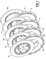
- a multiple disc brake made of composite material containing carbon for example in carbon-carbon composite material, in particular intended to form an airplane brake, comprises stator discs 10 alternating with rotor discs 20, as shown in FIG. 1.
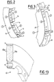
- the stator discs 10 (FIGS. 1 and 2) have two opposite annular faces 10a, 10b and, along their inner circumference, a crown 12 with notches or notches 14 intended to cooperate with grooves of a fixed hub (not shown ).
- the slots 16 between two notches can be provided with holes intended to allow the possible fixing of metal stirrups, in a manner known per se.
- each stator disc has its opposite faces 10a, 10b which constitute rubbing faces.
- the end stator discs 10 1 and 10 2 have only their internal faces which are rubbing.
- the external faces are intended to cooperate with plates (not shown) of a hydraulic device causing the mutual tightening of the discs during the braking command.
- the rotor discs 20 (FIGS. 1 and 3) have two rubbing faces opposite annulars 20a, 20b and, along their outer circumference, a crown 22 with notches or notches 24 intended to cooperate with internal splines of a sleeve (not shown) integral in rotation with a wheel.
- the slots 26 between two notches can be provided with holes intended for allow the possible fixing of metal stirrups, in a manner known per se.
- the reference 1 in a circle designates a face rubbing while the reference 2, in a circle, designates a part of the surface not rubbing.
- the non-friction parts constitute the whole of the surfaces of the discs except for rubbing faces.
- internal anti-oxidation protection is establishment by impregnation of the open internal porosity of the discs, after masking of rubbing faces.
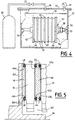
- a set of stator discs 10 is immersed in a bath 30 of a composition impregnation, inside a tank 32.
- the discs 10 have their rubbing faces masked in a liquid-tight manner by means of intermediate plates 40 and end 46.
- the plates 40, 46 are applied in leaktight manner at least the along the outer and inner edges of the rubbing faces using a tool 50 which encloses the disks arranged coaxially.
- Tool 50 includes two plates 52, 54 which are applied against the sealing plates 46 disposed at the ends of the disc assembly.
- the plates 52, 54 are connected by a rod axial 56 integral with one (52) of the plates and passing through the axial passages of the discs and a central hole formed in the other tray (54).
- the end of the rod 56 is threaded to allow mutual tightening of the plates by nuts 58.
- the tool 50 rests on supports 33 integral with the walls of the tank 32.
- the sealing plates 46 are tight annular rigid plates, for example of metal, material plastic or composite material. They have annular grooves 46a, 46b at near their inner and outer circumferences, on their turned faces to the discs. O-rings 48 of rubber are housed in the grooves 46a, 46b and are applied sealingly against the inner edges and outside of adjacent rubbing faces.
- FIG. 5 shows passages 53 formed through the plate 52 for allow access of the impregnation composition to the space 55 between the axial rod 56 and the set of surrounding annular discs and sealing plates this rod. Similar passages can be formed through the plate 54. In variant, access of the impregnating composition to space 55, on the edge side inside the discs, can be made through radial holes in the rod 56.
- the intermediate sealing plates 40 are rigid plates watertight annulars, also made of metal or plastic or composite. They have, on each face, annular grooves 42a, 42b, and 43a, 43b at neighborhood of their inner and outer circumferences. Seals O-rings 44 of rubber are housed in the grooves 42a, 42b, 43a, 43b and are tightly applied against the inside and outside edges of the faces adjacent rubs.
- the plates 40 and 46 slightly protrude from the faces adjacent rubs.
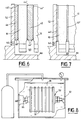
- the end plates 46 are provided, on their faces facing the discs, with elastic beads 48 '. These are made in one piece with the plates 46, for example by molding of rubber, or are bonded to the plates 46, these being or not rigid.
- the intermediate plates 40 are provided, on each face, of elastic beads 44 ′ made in one piece with the plates 40, for example by rubber molding, or bonded to the plates 40, these being rigid or not.
- the beads 48 ', 44' are located along the circumferences inner and outer plates 46, 40. They may have, in the undeformed state, a rectangular or rounded section.
- the plates ends 46 'and spacers 40' are formed simply by sheets elastically deformable annulars, for example of rubber. So he is important to distribute the clamping pressure correctly to ensure sealing along the inner and outer circumferences of the plates sealing.
- each side rubbing by forming a surface coating thereon, for example by spraying or spraying a non-porous layer, or by spreading and drying of a pasty rubber layer which can subsequently be peeled.
- the impregnation of the discs in the bath 30 is carried out under pressure.
- the tank 32 is closed in a sealed manner by a cover 34 through which passes a pipe 36 connecting the tank 32 to a pressure source 38 through a valve 37.
- a pressure gauge 39 makes it possible to measure the pressure inside the tank 32.
- the opening of the valve 37 allows to exert on the parts of exposed surfaces of the discs, that is to say all parts of surfaces not masked, a pressure higher than that prevailing initially inside the internal porosity of the discs.
- This difference of pressure dP causes the penetration of the impregnation composition into the discs, from exposed surfaces, until pressure balances between exposed surfaces and the core of the internal porosity of the discs in which the air content initially is still present.
- the penetration depth is a function the initial volume of the open internal porosity of the discs and the difference in pressure dP.
- the pressure difference dP is therefore adjusted in order to have a desired penetration depth. This must be sufficient, to allow the formation of an internal anti-oxidation protection in depth, while remaining limited to avoid significantly impregnating the porosity internal adjacent to the masked rubbing faces.
- the penetration depth is between approximately 2 mm and approximately 10 mm.
- the overpressure in tank 32 is maintained for a period sufficient to ensure impregnation to the desired depth, for example at less for 5 minutes.
- the discs are removed from the bath 30. There are, before removing the discs, a pressure at the heart of the discs greater than the ambient pressure. The pressure is rebalanced after withdrawal of the discs, through a macroporosity, in practice always present, of the material of the disk. Capillary forces and surface tensions are sufficient, due to the small dimension of the impregnated porosity, to oppose the expulsion of the impregnating composition having penetrated the porosity of the discs. It is however preferable to give the impregnating composition a viscosity not too much low, preferably greater than 0.1 dPa.s. However, this viscosity must not be too high not to make impregnation difficult, i.e. to be less than 10 dPa.s, preferably less than 1 dPa.s ..
- the impregnation composition is formed of precursors of the internal protection in suspension or in solution
- the impregnated discs are dried, for example by passing through an oven and then subjected to a heat treatment of transformation of precursors.
- heat treatment is usually done by raising gradually the temperature to about 350 ° C to 950 ° C.
- the discs are mounted coaxially with their horizontal axis, and the tool 50 is coupled to the output shaft 66 of a submerged motor 68 which drives the discs slow rotation around their axis.
- a sufficient impregnation depth can be obtained with a relatively small pressure difference dP, for example of the order of a tenth of an atmosphere (10 4 Pa).
- dP a relatively small pressure difference
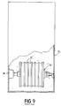
- Such overpressure can be obtained by immersing the discs at a suitable depth in a tank 72 filled with impregnation composition, as shown in FIG. 9.
- the discs are held coaxially in the tool 50 which is coupled to the shaft of output from a submerged motor 78.
- the drive of the rotating discs inside the bath makes it possible to standardize the overpressure exerted on the exposed surfaces of the discs, therefore to standardize the depth of impregnation.
- the pressure difference dP necessary for impregnation can be established not only by an overpressure exerted on the exposed surfaces of discs, but also at least partially by a depression established in the heart of the open internal porosity of the discs, as illustrated in FIGS. 10 to 12.
- stator discs 10 to impregnate are mounted in a tool identical to that of FIG. 4 and immersed in the bath 30.
- the rubbing faces of the discs are masked by two end plates 46 provided with O-rings 48 and intermediate plates 40 fitted with O-rings 44.
- the sealing plates, identical to those of Figures 4 and 5 are applied against the rubbing faces of the discs by tightening the assembly between the plates 52, 54 of the tool 50.
- the tank 32 is sealed by the cover 34 through which passes a pipe 86 connecting the tank 32 to a vacuum source 88 through a valve 87.
- the tank 32 is also connected to the pressure source 38 by means of the pipe 36 on which the valve 37 is mounted, as in the realization of figure 4.
- valve 87 After immersion of the discs 10 held in the tool 50, with their rubbing faces hidden, a depression is established in the tank 32 in opening the valve 87, the valve 37 being closed. This depression is limited in order to do not completely empty the internal porosity of the air discs that were there content initially.
- stator discs 10 to be impregnated are mounted in a tool 50 similar to that of FIG. 4 and immersed in the bath 30.
- the rubbing faces of the discs are masked by two end plates 46 provided with O-rings 48 and an intermediate plate 40 fitted with O-rings 44.
- the sealing plates similar to those of Figures 4 and 5 are applied against the rubbing faces of the discs by tightening the assembly between the plates 52, 54 of the tool 50.
- a waterproof plug 80 is formed through each end plate 46 while passages 81 are formed through the intermediate plates 40.
- the waterproof sockets 80 are connected by pipes 82 to a pipeline 86 connected to a vacuum source 88 via a valve 87.
- the sockets 80 are accessible through passages formed in the plates 52, 54.
- the opening of valve 87 allows the vacuum source to communicate with the space between each end plate 46 and the rubbing face which faces it and which is sealed from the impregnating composition bath.
- a vacuum is thus established within the open internal porosity of all discs, allowing the impregnation with the composition contained in the bath 30, the latter remaining exposed at ambient pressure.
- valve 87 When the impregnation is complete, the valve 87 is closed, now the depression within the internal porosity of the discs. Bath 30 is emptied, to allow the discs to dry. Maintaining depression opposes the expulsion of the impregnation composition out of the porosity of the discs, even with a very fluid composition.
- a single waterproof socket 80 through one of the two plates end 46 may be sufficient to put all the internal porosities of the discs in depression. It is also possible to provide one or more sockets lateral allowing access to the spaces between intermediate sealing plates and adjacent rubbing faces.
- the yield impregnation is higher when multiple discs are impregnated simultaneously, but the ability to soak the discs individually is not not excluded.
- stator discs The impregnation of stator discs has been described above. It seems immediately that impregnation of rotor discs 20 can be carried out in exactly the same way. It is also possible, using the same means for masking the rubbing faces, for simultaneously impregnating an assembly stator and rotor discs.
- the invention is applicable to the formation of a internal anti-oxidation protection on composite brake discs containing carbon other than that for use in aircraft brakes, for example discs for single disc or multiple disc brakes intended for land vehicles.
- the impregnation of the brake discs is produced with a solution of precursor salts of a glass composition having self-healing properties at operating temperatures of discs, such as glass composition based on phosphate.
- the molar ratio between modifying oxides and forming oxides is at least equal to 0, 6 and preferably at least equal to 0.9.
- aqueous solution stable impregnation without formation of phosphate precipitates
- to carry out the making the solution by first dissolving in water a polyphosphate capable of then allowing, by complexation, the dissolution of the necessary quantity of precursor salts of the modifying oxides, reaching a high concentration of precursor salts in the solution.
- Polyphosphate dissolved first is advantageously metaphosphate or trimetaphosphate of sodium.
- the zinc salt then added is preferably zinc nitrate or zinc sulfate.
- Aircraft brake stator discs are conventionally produced by carbon-carbon with internal and external diameters equal to 247 mm and 420 mm, a thickness equal to 26 mm and a residual internal porosity of approximately 10% by volume. After machining the notches on the internal crown of the discs, six of these discs are assembled coaxially by means of a tool 50 such as illustrated in figure 4. The rubbing faces of the discs are hidden so liquid-tight by means of annular end sealing plates 46 and spacers 40 fitted with rubber O-rings as illustrated by Figures 4 and 5.
- the plates 46 and 40 are made of aluminum alloy with PTFE (polytetrafluoroethylene) coating. Their inner diameters and outside are 270 mm and 430 mm respectively while those of rubbing faces of the discs are respectively equal to 280 mm and 420 mm.
- the discs mounted in the tool 50 are immersed in a bath 30 consisting of an aqueous solution of precursors of a phosphate-based glass.
- the solution has the following composition, in mass percentage (the figure in brackets indicates the order of introduction of the precursors of the constituent oxides of glass): H 2 O 42.5% NaPO 3 (1) 16.6% Zn (NO 3 ) 2 6H 2 O (2) 20.7% KH 2 PO 4 (3) 6.5% H 3 BO 3 (4) 1.6% H 6 NPO 4 (5) 12.1%
- the acidity of the solution is controlled in particular by potassium dihydrogen phosphate KH 2 PO 4 .
- the pH of the solution is approximately 0.3.
- the discs are kept immersed in the bath 30 for 5 minutes while an overpressure (dP) of 10 4 Pa (0.1 atmosphere) is established inside the tank 32 relative to the initial ambient pressure. Impregnation of the above solution is then carried out to an average depth of approximately 5 mm from the exposed surfaces of the discs.
- dP overpressure
- 10 4 Pa 0.1 atmosphere
- the impregnated discs are extracted from the bath, released from the tool 50 and dried in an oven before being heat treated in a neutral atmosphere at a temperature around 750 ° C.
- An internal anti-oxidation protection is then formed, consisting of a phosphate-based glass (glass 1) having, expressed in molar percentages of oxides, the following composition: P 2 O 5 45.6% ZnO 20.2% Na 2 O 23.5% K 2 O 6.9% B 2 O 3 3.8%, which gives a molar ratio of approximately 1.02 between glass-modifying oxides and glass-forming oxides (P 2 O 5 and B 2 O 3 ).
- Figure 13 illustrates, in section, the location of the internal protection anti-oxidation (hatched areas) in line with the non-friction surface parts of a disc 10 thus obtained.
- the internal protection 11 is slightly present at the edges rubbing faces 10a, 10b situated at the limit of the non-rubbing parts. This limited presence is not detrimental to tribological characteristics.
- test pieces made of carbon-carbon composite material identical to disc material above. Part of the test pieces is impregnated with the aqueous solution described above, precursor of the same phosphate-based glass. After drying and heat treatment under the same conditions, the mass relative of the glass formed within the test pieces is 2%.
- test tubes fitted with internal protection Part of the test tubes fitted with internal protection is polluted with potassium acetate, catalyst for carbon oxidation.
- Resistance to corrosion by humidity is measured by maintaining for 16 hours in water at room temperature of test tubes fitted with internal anti-oxidation protection identical to test pieces B above.
- the corrosion rate measured as a percentage of mass loss is equal to 1.87% / hour.
- the corrosion rate measured in the same conditions, with the same carbon-carbon test pieces provided internal protection obtained by impregnating with a solution aqueous sodium and potassium phosphates, as described in the document FR-A-2 685 694, is 10% / minute.
- Example 2 The procedure is as in Example 1 except that to the impregnation solution is added a concentrated solution at 50% of aluminum dihydrogen phosphate AlH 2 PO 4 in a proportion by mass of 30%. After heat treatment, an internal protection is obtained consisting of a glass composition (glass 2), the composition of which, expressed in molar percentages of oxides, is as follows: P 2 O 5 46.3% ZnO 16.2% Na 2 O 20.3% K 2 O 5.9% B 2 O 3 3.3% Al 2 O 3 7%, which gives a molar ratio of about 1.02 between modifying oxides and forming oxides (P 2 O 5 and B 2 O 3 ).
- Test pieces I are provided with an internal protection constituted by the glass 1 (example 1) while specimens II are provided with an internal protection constituted by the glass 2 (example 2), following the process described in example 1.
- Example 1 Although it was envisaged in Example 1 to carry out the heat treatment under a neutral atmosphere, it could be carried out under a reactive atmosphere, for example nitriding, under a mixture of ammonia and hydrogen (NH 3 + H 2 ), the nitriding of the glass being able to further improve its resistance to corrosion by humidity.
- a reactive atmosphere for example nitriding, under a mixture of ammonia and hydrogen (NH 3 + H 2 ), the nitriding of the glass being able to further improve its resistance to corrosion by humidity.
- This does not exclude the possibility of associating with this internal protection a external anti-oxidation protection in the form of an anchored surface coating in the surface porosity of the non-friction surface parts of the disc.
- This external protection preferably compatible with internal protection, is carried out for example by spraying or brushing a composition under form of a solution or suspension of precursors of external protection which, after drying, is subjected to a heat treatment.
- the composition containing the precursors of external protection can be implemented after impregnation with the precursor composition of internal protection and possibly drying, internal and external protections then being generated by the same heat treatment.
- the precursor composition of the external protection a composition analogous to the precursor impregnation composition of the external protection.
- Various constituents may however be added, in suspension or in solution, to give the external protection specific properties.
- refractory oxides for example silica (SiO 2 ) in colloidal form, can be added to give the external protection resistance to higher temperatures, compared to the internal protection, thus widening the range. operating temperature for the disc.
- Such external protection can be used for non- rubbing, opposite the rubbing faces, of stator discs located at the ends a multi-disc brake.
Landscapes
- Engineering & Computer Science (AREA)
- Chemical & Material Sciences (AREA)
- General Engineering & Computer Science (AREA)
- Ceramic Engineering (AREA)
- Materials Engineering (AREA)
- Structural Engineering (AREA)
- Mechanical Engineering (AREA)
- Organic Chemistry (AREA)
- Dispersion Chemistry (AREA)
- Physics & Mathematics (AREA)
- Plasma & Fusion (AREA)
- Composite Materials (AREA)
- Braking Arrangements (AREA)
- Application Of Or Painting With Fluid Materials (AREA)
Claims (44)
- Verfahren zum Anbringen eines Oxidationsschutzes auf einer Bremsscheibe aus einem Kohlenstoff enthaltenden Verbundmaterial, welches eine innere offene Restporosität aufweist,
dadurch gekennzeichnet,
daß es die folgenden Schritte aufweist:Abdecken jeder Reibfläche der Bremsscheibe, um sie von der äußeren Umgebung flüssigkeitsdicht zu isolieren, daraufhinEintauchen der Bremsscheibe in ein Bad einer Imprägnierungs-Zusammensetzung, die mindestens ein Produkt enthält, das fähig ist, die Bildung einer Oxidationsschutzschicht zu erlauben, undAusführen einer Imprägnierung durch Herstellen eines Unterschieds zwischen dem Druck außen an den exponierten Oberflächen der eingetauchten Bremsscheibe und dem Druck im Inneren der inneren offenen Porosität der Bremsscheibe, ohne diese völlig von der Luft, die sie enthält, zu entleeren, dergestalt, daß die Imprägnierungs-Zusammensetzung dazu gezwungen wird, in einer bestimmten Tiefe ausgehend von den exponierten Oberflächen in das Innere der inneren offenen Porosität einzudringen, um dort die Bildung eines inneren Oxidationsschutzes zu erlauben. - Verfahren nach Anspruch 1,
dadurch gekennzeichnet,
daß der Druckunterschied eingestellt wird in Abhängigkeit von der gewünschten Eindringtiefe der Imprägnierungs-Zusammensetzung in die innere offene Porosität. - Verfahren nach Anspruch 2,
dadurch gekennzeichnet,
daß der Druckunterschied eingestellt wird, um das Eindringen der Imprägnierungs-Zusammensetzung in einer Tiefe zwischen etwa 2 mm und etwa 10 mm zu erlauben. - Verfahren nach einem der Ansprüche 1 bis 3,
dadurch gekennzeichnet,
daß man außerhalb der exponierten Oberflächen der eingetauchten Bremsscheibe einen Druck herstellt, der höher ist als der zu Beginn im Inneren der inneren offenen Porosität der Bremsscheibe herrschende Umgebungsdruck. - Verfahren nach Anspruch 4,
dadurch gekennzeichnet,
daß die Bremsscheibe eingetaucht wird in das Bad im Inneren eines Behälters, in dem ein Überdruck hergestellt wird. - Verfahren nach Anspruch 5,
dadurch gekennzeichnet,
daß die in das Bad eingetauchte Bremsscheibe in Abhängigkeit von dem herzustellenden Überdruck von einem Flüssigkeitsstand überragt wird. - Verfahren nach einem der Ansprüche 1 bis 6,
dadurch gekennzeichnet,
daß die Imprägnierungs-Zusammensetzung eine Viskosität zwischen etwa 0,1 dPa·s und etwa 10 dPa·s hat. - Verfahren nach einem der Ansprüche 1 bis 7,
dadurch gekennzeichnet,
daß man im Inneren der inneren offenen Porosität der Bremsscheibe, ohne sie völlig zu entleeren, einen Druck unterhalb des Umgebungsdrucks, der dort zu Beginn herrschte, herstellt. - Verfahren nach Anspruch 8,
dadurch gekennzeichnet,
daß die Bremsscheibe in das Bad im Inneren eines Behälters eingetaucht wird, und daß man in dem Behälter zuerst einen ersten Druck herstellt, der niedriger ist als der dort zu Beginn herrschende Umgebungsdruck, und darauf einen zweiten Druck herstellt, der höher ist als der erste Druck. - Verfahren nach Anspruch 9,
dadurch gekennzeichnet,
daß der zweite Druck der Umgebungsdruck ist. - Verfahren nach Anspruch 8,
dadurch gekennzeichnet,
daß der niedrigere Druck hergestellt wird, indem man mindestens eine abgedeckte Reibfläche der Scheibe mit einer Vakuumquelle in Verbindung bringt. - Verfahren nach Anspruch 8 oder 11,
dadurch gekennzeichnet,
daß man den niedrigeren Druck im Inneren der inneren Porosität der Scheibe nach dem Ende der Imprägnierung beibehält. - Verfahren nach einem der Ansprüche 1 bis 12,
dadurch gekennzeichnet,
daß die Bremsscheibe in dem Bad der Imprägnierungs-Zusammensetzung um eine horizontale Achse herum drehend mitgenommen wird, um die Eindringtiefe der Imprägnierungs-Zusammensetzung gleichmäßig zu machen. - Verfahren nach einem der Ansprüche 1 bis 13,
dadurch gekennzeichnet,
daß das Abdecken einer Reibfläche mittels einer mindestens am äußeren Umfang der Reibfläche flüssigkeitsdicht angebrachten Platte durchgeführt wird. - Verfahren nach Anspruch 14,
dadurch gekennzeichnet,
daß die Platte steif ist und mit einer am äußeren Umfang der Reibfläche angebrachten Dichtung versehen ist. - Verfahren nach Anspruch 14,
dadurch gekennzeichnet,
daß die Platte nahe an ihrem Umfang mindestens eine Verdickung besitzt, die eine am Außenumfang der Reibfläche angebrachte Dichtung bildet. - Verfahren nach Anspruch 14,
dadurch gekennzeichnet,
daß die Platte ein gegen die Reibfläche gedrücktes Flachmaterialstück aus elastisch verformbarem Material ist. - Verfahren nach einem der Ansprüche 14 bis 17,
dadurch gekennzeichnet,
daß die Platte mittels eines Werkzeugs dicht auf der Reibfläche angebracht festgehalten wird. - Verfahren nach einem der Ansprüche 1 bis 18,
dadurch gekennzeichnet,
daß das Abdecken einer Reibfläche durchgeführt wird durch Anbringen eines Oberflächen-Belags, der vor dem Inbetriebsetzen der Bremsscheibe entfernt wird. - Verfahren nach Anspruch 19,
dadurch gekennzeichnet,
daß der Oberflächenbelag durch Aufspritzen angebracht wird. - Verfahren nach Anspruch 19 oder 20,
dadurch gekennzeichnet,
daß das Entfernen des Oberflächenbelags durch spanabhebende Bearbeitung durchgeführt wird. - Verfahren nach einem der Ansprüche 1 bis 18,
dadurch gekennzeichnet,
daß das Abdecken einer Reibfläche durchgeführt wird durch Abscheiden einer Kautschukschicht, die vor dem Inbetriebsetzen der Bremsscheibe durch Abziehen entfernt wird. - Verfahren nach einem der Ansprüche 1 bis 22,
dadurch gekennzeichnet,
daß man gleichzeitig mehrere Bremsscheiben, bei denen jede Reibfläche abgedeckt ist, in das Bad der Imprägnierungs-Zusammensetzung eintaucht. - Verfahren nach Anspruch 23,
dadurch gekennzeichnet,
daß die Bremsscheiben in einem Werkzeug koaxial angeordnet und aneinandergefügt werden. - Verfahren nach Anspruch 24, insofern als er von einem der Ansprüche 14 bis 18 abhängt,
dadurch gekennzeichnet,
daß das Abdecken zweier gegenüberliegender Reibflächen mittels der gleichen Platte durchgeführt wird, die mindestens am äußeren Umfang jeder der beiden Reibflächen flüssigkeitsdicht angebracht ist. - Verfahren nach einem der Ansprüche 22 bis 25 zum Anbringen eines Oxidationsschutzes auf einer Bremsscheibe, die dazu bestimmt ist, an einem Außenende eines Stapels von Statorscheiben, die mit Rotorscheiben abwechseln, befestigt zu werden, und die eine nicht reibende äußere Fläche entgegengesetzt zu einer inneren reibenden Fläche besitzt,
dadurch gekennzeichnet,
daß die nicht reibende Fläche während des Imprägnierungs-Schritts mindestens zum Teil abgedeckt wird, und nach Ausbildung des inneren Oxidationsschutzes mit einem Oberflächenbelag zum Schutz gegen Oxidation versehen wird. - Verfahren nach einem der Ansprüche 1 bis 26,
dadurch gekennzeichnet,
daß eine Imprägnierungs-Zusammensetzung verwendet wird, die besteht aus einer Lösung, die Vorläufer des Materials zum inneren Oxidationsschutz enthält, und dadurch, daß die Scheibe nach der Imprägnierung nacheinander einem Trocknen und einer thermischen Behandlung unterzogen wird. - Verfahren nach Anspruch 27,
dadurch gekennzeichnet,
daß die Imprägnierungs-Zusammensetzung aus einer Lösung besteht, die Vorläufer einer selbstheilenden Glaszusammensetzung auf dem Gebiet der Oxidation von Kohlenstoff enthält. - Verfahren nach Anspruch 28,
dadurch gekennzeichnet,
daß die Imprägnierungs-Zusammensetzung aus einer Lösung besteht, die Phosphate enthält, um eine Glaszusammensetzung auf Phosphat-Basis zu bilden. - Verfahren nach Anspruch 29,
dadurch gekennzeichnet,
daß die Imprägnierungs-Zusammensetzung aus einer Lösung besteht, die Phosphate und mindestens ein Vorläufersalz von Zinkoxid enthält. - Verfahren nach Anspruch 29,
dadurch gekennzeichnet,
daß die Imprägnierungs-Zusammensetzung aus einer wässrigen Lösung besteht, die Vorläufer einer Glaszusammensetzung enthält, die, in Molen Oxid ausgedrückt, die folgende Zusammensetzung hat:20 bis 60% P2O5,10 bis 30% ZnO,10 bis 30% Na2O,0 bis 20% mindestens eines Oxids, das ausgewählt ist aus CuO, CoO, NiO, FeO, MgO und PbO,0 bis 15% mindestens eines Alkalimetalloxids, das ausgewählt ist aus Li2O und K2O,0 bis 20% mindestens eines Oxids, das ausgewählt ist aus Bi2O3, Al2O3 und B2O3, und0 bis 5% mindestens eines Oxids, das ausgewählt ist aus V2O5 und TiO2. - Verfahren nach Anspruch 31, dadurch gekennzeichnet, daß die Glaszusammensetzung, in Molen Oxid ausgedrückt, die folgende Zusammensetzung hat:20 bis 50% P2O5,10 bis 30% ZnO,10 bis 30% Na2O,0 bis 20% mindestens eines Oxids, das ausgewählt ist aus CuO, CoO, NiO, FeO, MgO und PbO,0 bis 15% mindestens eines Alkalimetalloxids, das ausgewählt ist aus Li2O und K2O,0 bis 15% mindestens eines Oxids, das ausgewählt ist aus Bi2O3, Al2O3 und B2O3 und0 bis 5% mindestens eines Oxids, das ausgewählt ist aus V2O5 und TiO2.
- Verfahren nach Anspruch 31 oder 32,
dadurch gekennzeichnet,
daß für das Molverhältnis von glasmodifizierenden Oxiden, die ZnO enthalten, und glasbildenden Oxiden, die im wesentlichen oder nur P2O5 enthalten, ein ausreichend hoher Wert gewählt wird, daß die Glaszusammensetzung Beständigkeit gegen Korrosion durch Feuchtigkeit aufweist. - Verfahren nach Anspruch 33,
dadurch gekennzeichnet,
daß das Molverhältnis mindestens gleich 0,6 ist. - Verfahren nach Anspruch 34,
dadurch gekennzeichnet,
daß das Molverhältnis mindestens gleich 0,9 ist. - Verfahren nach einem der Ansprüche 30 bis 35,
dadurch gekennzeichnet,
daß die Imprägnierungs-Lösung hergestellt wird durch Lösen in Wasser von zuerst einem Polyphosphat, das ausgewählt ist aus Natrium-metaphosphat und Natrium-trimetaphosphat, dann einem Zinksalz, das ausgewählt ist aus Zinknitrat und Zinksulfat. - Verfahren nach einem der Ansprüche 30 bis 36,
dadurch gekennzeichnet,
daß die Lösung sauer ist mit einem pH unter 0,5. - Verfahren nach einem der Ansprüche 28 bis 37,
dadurch gekennzeichnet,
daß die thermische Behandlung in reaktiver Umgebung durchgeführt wird. - Verfahren nach einem der Ansprüche 1 bis 26,
dadurch gekennzeichnet,
daß eine Imprägnierungs-Zusammensetzung verwendet wird, die aus einem Gemisch von Bestandteilen des Materials zum inneren Oxidationsschutz im geschmolzenen Zustand besteht. - Verfahren nach einem der Ansprüche 1 bis 26,
dadurch gekennzeichnet,
daß eine Imprägnierungs-Zusammensetzung verwendet wird, die besteht aus einem Gemisch von Vorläufern der Bestandteile des Materials zum inneren Schutz in Form von Pulvern in Suspension in einer Flüssigkeit. - Verfahren nach einem der Ansprüche 1 bis 40,
dadurch gekennzeichnet,
daß die nicht reibenden Oberflächenbereiche der Bremsscheibe mit einem äußeren Oxidationsschutz versehen werden. - Verfahren nach Anspruch 41,
dadurch gekennzeichnet,
daß der äußere Schutz hergestellt wird durch Bilden eines Oberflächenbelags, der mit dem inneren Schutzmaterial verträglich ist. - Verfahren nach einem der Ansprüche 28 bis 38,
dadurch gekennzeichnet,
daß die nicht reibenden Oberflächenbereiche der Bremsscheibe mit einem äußeren Oxidationsschutz versehen werden durch Abscheidung einer Oberflächenschicht, die auf der Basis der Imprägnierungs-Lösung hergestellt wird. - Verfahren nach Anspruch 43,
dadurch gekennzeichnet,
daß, zur Ausbildung des äußeren Schutzes, der Lösung Siliciumoxid in koloidaler Form zugefügt wird.
Applications Claiming Priority (3)
| Application Number | Priority Date | Filing Date | Title |
|---|---|---|---|
| FR9403972 | 1994-04-05 | ||
| FR9403972A FR2718130B1 (fr) | 1994-04-05 | 1994-04-05 | Procédé pour l'application d'une protection anti-oxydation sur des disques de frein en matériau composite contenant du carbone. |
| PCT/FR1995/000431 WO1995026941A1 (fr) | 1994-04-05 | 1995-04-05 | Procede pour l'application d'une protection anti-oxydation sur des disques de frein en materiau composite contenant du carbone |
Publications (2)
| Publication Number | Publication Date |
|---|---|
| EP0703882A1 EP0703882A1 (de) | 1996-04-03 |
| EP0703882B1 true EP0703882B1 (de) | 1998-12-16 |
Family
ID=9461741
Family Applications (1)
| Application Number | Title | Priority Date | Filing Date |
|---|---|---|---|
| EP95916708A Expired - Lifetime EP0703882B1 (de) | 1994-04-05 | 1995-04-05 | Verfahrem zum anbringen eines oxidationsschutz auf bremsscheiben aus kohlenstoff enthaltendem verbundmaterial |
Country Status (10)
| Country | Link |
|---|---|
| US (1) | US5686144A (de) |
| EP (1) | EP0703882B1 (de) |
| JP (1) | JP3647870B2 (de) |
| CA (1) | CA2164091C (de) |
| DE (1) | DE69506653T2 (de) |
| ES (1) | ES2126275T3 (de) |
| FR (1) | FR2718130B1 (de) |
| RU (1) | RU2126502C1 (de) |
| UA (1) | UA40619C2 (de) |
| WO (1) | WO1995026941A1 (de) |
Families Citing this family (69)
| Publication number | Priority date | Publication date | Assignee | Title |
|---|---|---|---|---|
| GB9525622D0 (en) * | 1995-12-15 | 1996-02-14 | Sab Wabco Bromborough Limited | Friction engaging device |
| WO1997033706A1 (en) * | 1996-03-15 | 1997-09-18 | Kawasaki Steel Corporation | Ultra-thin sheet steel and method for manufacturing the same |
| DE29610498U1 (de) * | 1996-06-14 | 1996-08-29 | Zornik, Miklavz, Lesce | Fahrzeugbrems- bzw. Fahrzeugkupplungsscheibe aus C-C/SiC-Werkstoff |
| IN195165B (de) * | 1996-06-21 | 2005-01-28 | Engelhard Corp | |
| US5962135A (en) * | 1997-04-09 | 1999-10-05 | Alliedsignal Inc. | Carbon/carbon friction material |
| US5964022A (en) * | 1997-12-29 | 1999-10-12 | Ford Global Technologies, Inc. | Method of joining brake assemblies to wheel hubs |
| US5981002A (en) * | 1998-02-09 | 1999-11-09 | Textron Systems Corporation | Method for densifying the edges and surfaces of a preform using a liquid precursor |
| US6340090B1 (en) * | 1999-01-07 | 2002-01-22 | Tooltek Engineering Corporation | Substrate fixturing device |
| US6913821B2 (en) * | 1999-03-04 | 2005-07-05 | Honeywell International Inc. | Fluidizing oxidation protection systems |
| US6737120B1 (en) | 1999-03-04 | 2004-05-18 | Honeywell International Inc. | Oxidation-protective coatings for carbon-carbon components |
| US6136374A (en) * | 1999-10-14 | 2000-10-24 | Reuscher; Craig J. | Method and apparatus for coating vented brake rotors |
| DE10131769C5 (de) * | 2001-06-30 | 2010-02-18 | Audi Ag | Bremssystem mit Verbundwerkstoff-Bremsscheibe |
| DE10133635A1 (de) * | 2001-07-11 | 2003-02-06 | Sgl Carbon Ag | Mehrschichtiger Keramik-Verbund |
| DE10134059C1 (de) * | 2001-07-13 | 2003-04-03 | Porsche Ag | Oxydationsgeschützte Bremsscheibe |
| DE10155901A1 (de) * | 2001-11-14 | 2003-05-15 | Mann & Hummel Filter | Verfahren zur Erzeugung von einer Beschichtung auf einer Hohlfaser |
| US6884467B2 (en) * | 2002-08-20 | 2005-04-26 | Honeywell International Inc. | Method for simultaneously protecting carbon-containing components against catalytic oxidation and high temperature non-catalytic oxidation |
| US6685776B1 (en) * | 2002-11-18 | 2004-02-03 | Emerson Power Transmission Manufacturing, L.P. | Bearing component masking unit |
| US7008498B2 (en) | 2003-04-18 | 2006-03-07 | Delphi Technologies, Inc. | Coating method for disc brake pads |
| US7641941B2 (en) * | 2003-04-22 | 2010-01-05 | Goodrich Corporation | Oxidation inhibition of carbon-carbon composites |
| DE10343946B4 (de) * | 2003-09-23 | 2006-03-02 | Holger Sprenger | Verfahren zur partiellen Oberflächenbehandlung von Rädern oder Wellen |
| US7241476B2 (en) * | 2004-09-16 | 2007-07-10 | Honeywell International Inc. | Airflow masking of carbon-carbon composites for application of antioxidants |
| GB2426756A (en) * | 2005-06-03 | 2006-12-06 | Huntercombe Consultancy Ltd | Porous body containing within its pores a chemically bonded phosphate ceramic |
| FR2893939B1 (fr) * | 2005-11-29 | 2008-02-22 | Snecma Propulsion Solide Sa | Protection contre l'oxydation de materiaux composites contenant du carbone |
| US20070154712A1 (en) * | 2005-12-22 | 2007-07-05 | Mazany Anthony M | Oxidation inhibition of carbon-carbon composites |
| EP2302250B1 (de) * | 2006-05-01 | 2012-07-04 | American Precision Industries Inc. | Brems- oder Kupplungsvorrichtung |
| EP1889822A3 (de) * | 2006-08-18 | 2009-03-04 | Honeywell International Inc. | Zweiteiliger Kohlenstoff-Kohlenstoff-Druckplattenentwurf für Flugzeugbremsen |
| EP2231341B1 (de) * | 2008-01-08 | 2018-12-26 | Freni Brembo S.p.A. | Verfahren und vorrichtung zum beschichten der lüftungskammer von rotoren für scheibenbremsen mit einer schutzschicht |
| US8801981B2 (en) | 2008-11-25 | 2014-08-12 | Honeywell International Inc. | Preventing carbon AO migration by limiting surface porosity |
| DE102009035968B8 (de) * | 2009-08-04 | 2013-05-02 | A. Meier KG | Verfahren und Vorrichtung zum Benetzen und/oder Versiegeln von elektrischen Bauteilen |
| EP2336592A1 (de) * | 2009-12-18 | 2011-06-22 | PFW Aerospace AG | Bremsscheibensatz mit Inertgassystem für ein Flugzeug |
| DE102010038914A1 (de) * | 2010-08-04 | 2012-02-09 | Sgl Carbon Se | Vorrichtung und Verfahren zum Silizieren |
| DE102013221737A1 (de) * | 2013-10-25 | 2015-04-30 | Ford Global Technologies, Llc | Verfahren zur Herstellung einer Bremsscheibe sowie Bremsscheibe |
| JP2015100761A (ja) * | 2013-11-26 | 2015-06-04 | 曙ブレーキ工業株式会社 | 支持具、粉体塗布システム、粉体塗布方法、及びキャリパ |
| GB2521597A (en) * | 2013-11-27 | 2015-07-01 | Aston Martin Lagonda Ltd | Brake conditioning |
| US20160348744A1 (en) * | 2014-02-05 | 2016-12-01 | Ford Global Technologies, Llc | Method for producing a brake disc and brake disc |
| KR101543218B1 (ko) * | 2014-02-25 | 2015-08-10 | (주) 데크카본 | 항공기 브레이크 디스크 및 이를 만드는 방법 |
| DE102014205666A1 (de) * | 2014-03-26 | 2015-10-01 | Ford Global Technologies, Llc | Verfahren zur Herstellung einer Bremsscheibe sowie Bremsscheibe |
| DE102015212511B4 (de) * | 2014-07-24 | 2019-06-06 | Ford Global Technologies, Llc | Verfahren zur Herstellung einer Bremsscheibe sowie Bremsscheibe |
| USD784221S1 (en) * | 2015-03-24 | 2017-04-18 | Shandong Haoxin Machinery Co., Ltd. | Brake drum |
| US10087101B2 (en) | 2015-03-27 | 2018-10-02 | Goodrich Corporation | Formulations for oxidation protection of composite articles |
| DE102015207164B4 (de) * | 2015-04-21 | 2023-06-22 | Aktiebolaget Skf | Abdeckvorrichtung zur partiellen Abdeckung eines Lagerrings in einem Behandlungsbad und Verfahren zur partiellen Behandlung eines Lagerrings |
| US10302163B2 (en) | 2015-05-13 | 2019-05-28 | Honeywell International Inc. | Carbon-carbon composite component with antioxidant coating |
| US10131113B2 (en) | 2015-05-13 | 2018-11-20 | Honeywell International Inc. | Multilayered carbon-carbon composite |
| US9944526B2 (en) | 2015-05-13 | 2018-04-17 | Honeywell International Inc. | Carbon fiber preforms |
| US10035305B2 (en) | 2015-06-30 | 2018-07-31 | Honeywell International Inc. | Method of making carbon fiber preforms |
| US10022890B2 (en) | 2015-09-15 | 2018-07-17 | Honeywell International Inc. | In situ carbonization of a resin to form a carbon-carbon composite |
| US10300631B2 (en) | 2015-11-30 | 2019-05-28 | Honeywell International Inc. | Carbon fiber preforms |
| US10465285B2 (en) | 2016-05-31 | 2019-11-05 | Goodrich Corporation | High temperature oxidation protection for composites |
| US10377675B2 (en) | 2016-05-31 | 2019-08-13 | Goodrich Corporation | High temperature oxidation protection for composites |
| US10508206B2 (en) | 2016-06-27 | 2019-12-17 | Goodrich Corporation | High temperature oxidation protection for composites |
| US10767059B2 (en) | 2016-08-11 | 2020-09-08 | Goodrich Corporation | High temperature oxidation protection for composites |
| US10526253B2 (en) | 2016-12-15 | 2020-01-07 | Goodrich Corporation | High temperature oxidation protection for composites |
| FR3071830B1 (fr) * | 2017-10-02 | 2021-03-12 | Safran Ceram | Procede pour la realisation d'une piece creuse en materiau composite a matrice ceramique |
| US11046619B2 (en) | 2018-08-13 | 2021-06-29 | Goodrich Corporation | High temperature oxidation protection for composites |
| US11634213B2 (en) | 2018-11-14 | 2023-04-25 | Goodrich Corporation | High temperature oxidation protection for composites |
| GB201820560D0 (en) | 2018-12-17 | 2019-01-30 | Aston Martin Lagonda Ltd | Assemblies for engines |
| FR3095436B1 (fr) | 2019-04-24 | 2021-04-02 | Safran Ceram | Procédé de protection contre l’oxydation d’une pièce en matériau composite comprenant du carbone |
| WO2021130862A1 (ja) * | 2019-12-24 | 2021-07-01 | 住友電工焼結合金株式会社 | 架橋フッ素樹脂コーティングロータの製造方法 |
| US12246994B2 (en) | 2019-12-27 | 2025-03-11 | Goodrich Corporation | High temperature oxidation protection for composites |
| US12330996B2 (en) | 2021-05-05 | 2025-06-17 | Goodrich Corporation | High temperature oxidation protection for carbon-carbon composites |
| CN113941371B (zh) * | 2021-09-27 | 2022-12-16 | 南京工业大学 | 一种变温真空涂覆方式制备堇青石整体式催化剂的方法 |
| US12065380B2 (en) | 2021-11-16 | 2024-08-20 | Goodrich Corporation | High temperature oxidation protection for carbon-carbon composites |
| US12344564B2 (en) | 2022-01-07 | 2025-07-01 | Goodrich Corporation | Oxidation protection with improved water resistance for composites |
| JP7433355B2 (ja) * | 2022-03-30 | 2024-02-19 | 本田技研工業株式会社 | 回転電機用ステータの製造方法 |
| US12319622B2 (en) | 2022-05-18 | 2025-06-03 | Goodrich Corporation | Oxidation protection of composites |
| US12565450B2 (en) | 2022-06-17 | 2026-03-03 | Goodrich Corporation | Oxidation protection for carbon-carbon composites |
| FR3138430B1 (fr) * | 2022-07-26 | 2025-07-18 | Safran Landing Systems | Procédé de protection contre l’oxydation d’une pièce en matériau composite comprenant du carbone |
| US12583785B2 (en) | 2023-03-20 | 2026-03-24 | Goodrich Corporation | Advanced oxidation protection system with broad temperature range capability |
| US12559634B2 (en) | 2023-03-20 | 2026-02-24 | Goodrich Corporation | Oxidation protective systems and methods of manufacture |
Family Cites Families (10)
| Publication number | Priority date | Publication date | Assignee | Title |
|---|---|---|---|---|
| DE1596487B2 (de) * | 1967-01-05 | 1970-10-08 | Heinrich Koppers Gmbh, 4300 Essen | Verfahren zur Vorbehandlung von Formkörpern aus keramischem Material, deren Oberfläche mit geschmolzenem Glae in Berührung kommt |
| US3850669A (en) * | 1972-09-25 | 1974-11-26 | Toyo Kogyo Co | Metal spraying process |
| GB1544994A (en) * | 1975-12-03 | 1979-04-25 | Goodyear Aerospace Corp | Carbon brake disc having oxidation limiting coating |
| US4169667A (en) * | 1977-03-23 | 1979-10-02 | Gaf Corporation | Film buffer for motion picture projectors |
| US4617232A (en) * | 1982-04-15 | 1986-10-14 | Kennecott Corporation | Corrosion and wear resistant graphite material |
| US4454193A (en) * | 1983-02-28 | 1984-06-12 | Union Oil Company Of California | Carbon-metal phosphate ester composite and method of making |
| US4550034A (en) * | 1984-04-05 | 1985-10-29 | Engelhard Corporation | Method of impregnating ceramic monolithic structures with predetermined amounts of catalyst |
| CA1333073C (en) * | 1988-10-17 | 1994-11-15 | George Halsey Beall | Zinc-containing phosphate glasses |
| US5073405A (en) * | 1991-01-15 | 1991-12-17 | Westinghouse Electric Corp. | Applying a tapered electrode on a porous ceramic support tube by masking a band inside the tube and drawing in electrode material from the outside of the tube by suction |
| FR2685694B1 (fr) * | 1991-12-30 | 1994-06-03 | Europ Propulsion | Procede pour la protection contre l'oxydation de produits en materiau composite contenant du carbone, et produits obtenus par le procede. |
-
1994
- 1994-04-05 FR FR9403972A patent/FR2718130B1/fr not_active Expired - Fee Related
-
1995
- 1995-04-05 UA UA95125127A patent/UA40619C2/uk unknown
- 1995-04-05 JP JP52547395A patent/JP3647870B2/ja not_active Expired - Fee Related
- 1995-04-05 ES ES95916708T patent/ES2126275T3/es not_active Expired - Lifetime
- 1995-04-05 DE DE69506653T patent/DE69506653T2/de not_active Expired - Lifetime
- 1995-04-05 EP EP95916708A patent/EP0703882B1/de not_active Expired - Lifetime
- 1995-04-05 WO PCT/FR1995/000431 patent/WO1995026941A1/fr not_active Ceased
- 1995-04-05 RU RU96101166A patent/RU2126502C1/ru active
- 1995-04-05 US US08/556,945 patent/US5686144A/en not_active Expired - Lifetime
- 1995-04-05 CA CA002164091A patent/CA2164091C/en not_active Expired - Fee Related
Also Published As
| Publication number | Publication date |
|---|---|
| JPH08511334A (ja) | 1996-11-26 |
| UA40619C2 (uk) | 2001-08-15 |
| DE69506653D1 (de) | 1999-01-28 |
| WO1995026941A1 (fr) | 1995-10-12 |
| US5686144A (en) | 1997-11-11 |
| EP0703882A1 (de) | 1996-04-03 |
| RU2126502C1 (ru) | 1999-02-20 |
| ES2126275T3 (es) | 1999-03-16 |
| CA2164091C (en) | 2005-09-27 |
| FR2718130B1 (fr) | 1996-06-21 |
| MX9505039A (es) | 1998-03-31 |
| DE69506653T2 (de) | 1999-07-22 |
| JP3647870B2 (ja) | 2005-05-18 |
| CA2164091A1 (en) | 1995-10-12 |
| FR2718130A1 (fr) | 1995-10-06 |
Similar Documents
| Publication | Publication Date | Title |
|---|---|---|
| EP0703882A1 (de) | Verfahrem zum anbringen eines oxidationsschutz auf bremsscheiben aus kohlenstoff enthaltendem verbundmaterial | |
| EP0789677B1 (de) | Verfahren zum aufbringen eines oxydationsschutzes auf kohlenstoff enthaltende verbundmaterialen | |
| EP1594816B1 (de) | Verfahren zur silizierung von thermostrukturellen verbundwerkstoffen und so hergestellte teile | |
| EP1917453B1 (de) | Antioxidationsschutz von gegenständen aus kohlenstoffhaltigem verbundwerkstoff | |
| EP2930162B1 (de) | Schutz gegen oxidation von kohlenstoffhaltigen werkstücken aus verbundmaterial | |
| EP0701538B1 (de) | Verfahren zum schützen eines porösen kohlenstoffhaltigen material und das so erhaltene material | |
| FR2525207A1 (fr) | Production d'articles en carbone plein, resistants a la corrosion et a l'erosion | |
| EP1957431B1 (de) | Oxidierungsschutz für verbundwerkstoffe mit kohlenstoff | |
| EP3530637A1 (de) | Verfahren zum schutz gegen oxidation eines verbundwerkstücks | |
| WO1998016484A1 (fr) | Element de friction en materiau composite carbone/carbone-carbure de silicium et procede pour sa fabrication | |
| FR2869609A1 (fr) | Procede de fabrication d'une piece en materiau composite thermostructural | |
| EP1648842B1 (de) | Schutz von kohlenstoff enthaltenden verbundmaterialteilchen gegen oxidation und so geschützte teile | |
| EP0223642B1 (de) | Kohlenstoff-Kohlenstoff-Verbundwerkstoff für Friktionserzeugnisse und seine Verwendung für Bremsanlage | |
| FR2490398A1 (fr) | Cible perfectionnee pour anode tournante de tube de rayons x et son procede de fabrication | |
| WO2015036974A1 (fr) | Substrat à revêtement peu perméable pour solidification de silicium | |
| BE1008162A5 (fr) | Produits manufactures carbones et procede pour les produire. | |
| FR3158964A1 (fr) | Couche de protection contre l’oxydation thermique d’une pièce en matériau composite comprenant du carbone | |
| WO2023031548A1 (fr) | Procede de protection contre l'oxydation d'une piece en materiau composite carbone/carbone | |
| WO2015036975A1 (fr) | Substrat pour la solidification de lingot de silicium | |
| EP0634378B1 (de) | Verfahren zur Verbesserung de Oxidationsbeständigkeit von faserverstärkten Verbundstoffen mit einer Glas-, Keramik- oder Glaskeramikmatrix |
Legal Events
| Date | Code | Title | Description |
|---|---|---|---|
| PUAI | Public reference made under article 153(3) epc to a published international application that has entered the european phase |
Free format text: ORIGINAL CODE: 0009012 |
|
| 17P | Request for examination filed |
Effective date: 19960113 |
|
| AK | Designated contracting states |
Kind code of ref document: A1 Designated state(s): BE CH DE ES FR GB IT LI NL SE |
|
| RAP1 | Party data changed (applicant data changed or rights of an application transferred) |
Owner name: SOCIETE EUROPEENNE DE PROPULSION |
|
| 17Q | First examination report despatched |
Effective date: 19961206 |
|
| GRAG | Despatch of communication of intention to grant |
Free format text: ORIGINAL CODE: EPIDOS AGRA |
|
| RAP1 | Party data changed (applicant data changed or rights of an application transferred) |
Owner name: SOCIETE NATIONALE D'ETUDE ET DE CONSTRUCTION DE MO |
|
| GRAG | Despatch of communication of intention to grant |
Free format text: ORIGINAL CODE: EPIDOS AGRA |
|
| GRAH | Despatch of communication of intention to grant a patent |
Free format text: ORIGINAL CODE: EPIDOS IGRA |
|
| GRAH | Despatch of communication of intention to grant a patent |
Free format text: ORIGINAL CODE: EPIDOS IGRA |
|
| GRAH | Despatch of communication of intention to grant a patent |
Free format text: ORIGINAL CODE: EPIDOS IGRA |
|
| GRAA | (expected) grant |
Free format text: ORIGINAL CODE: 0009210 |
|
| AK | Designated contracting states |
Kind code of ref document: B1 Designated state(s): BE CH DE ES FR GB IT LI NL SE |
|
| REG | Reference to a national code |
Ref country code: CH Ref legal event code: NV Representative=s name: MICHELI & CIE INGENIEURS-CONSEILS Ref country code: CH Ref legal event code: EP |
|
| ITF | It: translation for a ep patent filed | ||
| REF | Corresponds to: |
Ref document number: 69506653 Country of ref document: DE Date of ref document: 19990128 |
|
| REG | Reference to a national code |
Ref country code: ES Ref legal event code: FG2A Ref document number: 2126275 Country of ref document: ES Kind code of ref document: T3 |
|
| GBT | Gb: translation of ep patent filed (gb section 77(6)(a)/1977) |
Effective date: 19990311 |
|
| PLBE | No opposition filed within time limit |
Free format text: ORIGINAL CODE: 0009261 |
|
| STAA | Information on the status of an ep patent application or granted ep patent |
Free format text: STATUS: NO OPPOSITION FILED WITHIN TIME LIMIT |
|
| 26N | No opposition filed | ||
| REG | Reference to a national code |
Ref country code: GB Ref legal event code: IF02 |
|
| REG | Reference to a national code |
Ref country code: FR Ref legal event code: TP Ref country code: FR Ref legal event code: CD |
|
| PGFP | Annual fee paid to national office [announced via postgrant information from national office to epo] |
Ref country code: CH Payment date: 20040325 Year of fee payment: 10 |
|
| PG25 | Lapsed in a contracting state [announced via postgrant information from national office to epo] |
Ref country code: LI Free format text: LAPSE BECAUSE OF NON-PAYMENT OF DUE FEES Effective date: 20050430 Ref country code: CH Free format text: LAPSE BECAUSE OF NON-PAYMENT OF DUE FEES Effective date: 20050430 |
|
| REG | Reference to a national code |
Ref country code: CH Ref legal event code: PL |
|
| BECA | Be: change of holder's address |
Owner name: SNECMA PROPULSION SOLIDELES CINQ CHEMINS, F-33187 Effective date: 20090403 |
|
| BECH | Be: change of holder |
Owner name: SNECMA PROPULSION SOLIDE Effective date: 20090403 |
|
| BECN | Be: change of holder's name |
Owner name: SNECMA PROPULSION SOLIDELES CINQ CHEMINS, F-33187 Effective date: 20090403 Owner name: SNECMA PROPULSION SOLIDE Effective date: 20090403 |
|
| NLS | Nl: assignments of ep-patents |
Owner name: LEXVALL Effective date: 20090212 Owner name: LEXVALL 8 Effective date: 20090212 |
|
| NLT1 | Nl: modifications of names registered in virtue of documents presented to the patent office pursuant to art. 16 a, paragraph 1 |
Owner name: SNECMA MOTEURS Owner name: SNECMA PROPULSION SOLIDE |
|
| PGFP | Annual fee paid to national office [announced via postgrant information from national office to epo] |
Ref country code: ES Payment date: 20090407 Year of fee payment: 15 Ref country code: BE Payment date: 20090324 Year of fee payment: 15 |
|
| PGFP | Annual fee paid to national office [announced via postgrant information from national office to epo] |
Ref country code: SE Payment date: 20090325 Year of fee payment: 15 Ref country code: NL Payment date: 20090326 Year of fee payment: 15 Ref country code: IT Payment date: 20090401 Year of fee payment: 15 |
|
| REG | Reference to a national code |
Ref country code: FR Ref legal event code: TP |
|
| BERE | Be: lapsed |
Owner name: SNECMA PROPULSION SOLIDE Effective date: 20100430 |
|
| REG | Reference to a national code |
Ref country code: NL Ref legal event code: V1 Effective date: 20101101 |
|
| EUG | Se: european patent has lapsed | ||
| PG25 | Lapsed in a contracting state [announced via postgrant information from national office to epo] |
Ref country code: NL Free format text: LAPSE BECAUSE OF NON-PAYMENT OF DUE FEES Effective date: 20101101 |
|
| PG25 | Lapsed in a contracting state [announced via postgrant information from national office to epo] |
Ref country code: IT Free format text: LAPSE BECAUSE OF NON-PAYMENT OF DUE FEES Effective date: 20100405 Ref country code: BE Free format text: LAPSE BECAUSE OF NON-PAYMENT OF DUE FEES Effective date: 20100430 |
|
| REG | Reference to a national code |
Ref country code: ES Ref legal event code: FD2A Effective date: 20110718 |
|
| PG25 | Lapsed in a contracting state [announced via postgrant information from national office to epo] |
Ref country code: ES Free format text: LAPSE BECAUSE OF NON-PAYMENT OF DUE FEES Effective date: 20110706 |
|
| PGFP | Annual fee paid to national office [announced via postgrant information from national office to epo] |
Ref country code: DE Payment date: 20110404 Year of fee payment: 17 |
|
| PG25 | Lapsed in a contracting state [announced via postgrant information from national office to epo] |
Ref country code: ES Free format text: LAPSE BECAUSE OF NON-PAYMENT OF DUE FEES Effective date: 20100406 |
|
| REG | Reference to a national code |
Ref country code: FR Ref legal event code: CD Owner name: MESSIER-BUGATTI-DOWTY, FR Effective date: 20120321 Ref country code: FR Ref legal event code: CA Effective date: 20120321 |
|
| REG | Reference to a national code |
Ref country code: DE Ref legal event code: R082 Ref document number: 69506653 Country of ref document: DE Representative=s name: CBDL PATENTANWAELTE, DE |
|
| REG | Reference to a national code |
Ref country code: DE Ref legal event code: R082 Ref document number: 69506653 Country of ref document: DE Representative=s name: CBDL PATENTANWAELTE, DE Effective date: 20120808 Ref country code: DE Ref legal event code: R081 Ref document number: 69506653 Country of ref document: DE Owner name: MESSIER-BUGATTI-DOWTY, FR Free format text: FORMER OWNER: MESSIER-BUGATTI, VELIZY VILLACOUBLAY, FR Effective date: 20120808 |
|
| PG25 | Lapsed in a contracting state [announced via postgrant information from national office to epo] |
Ref country code: SE Free format text: LAPSE BECAUSE OF NON-PAYMENT OF DUE FEES Effective date: 20100406 |
|
| REG | Reference to a national code |
Ref country code: DE Ref legal event code: R119 Ref document number: 69506653 Country of ref document: DE Effective date: 20121101 |
|
| PGFP | Annual fee paid to national office [announced via postgrant information from national office to epo] |
Ref country code: GB Payment date: 20140327 Year of fee payment: 20 |
|
| PGFP | Annual fee paid to national office [announced via postgrant information from national office to epo] |
Ref country code: FR Payment date: 20140418 Year of fee payment: 20 |
|
| PG25 | Lapsed in a contracting state [announced via postgrant information from national office to epo] |
Ref country code: DE Free format text: LAPSE BECAUSE OF NON-PAYMENT OF DUE FEES Effective date: 20121101 |
|
| REG | Reference to a national code |
Ref country code: GB Ref legal event code: PE20 Expiry date: 20150404 |
|
| PG25 | Lapsed in a contracting state [announced via postgrant information from national office to epo] |
Ref country code: GB Free format text: LAPSE BECAUSE OF EXPIRATION OF PROTECTION Effective date: 20150404 |