EP0703871B1 - Vehicule a auto-chargement et a fleche articulee - Google Patents
Vehicule a auto-chargement et a fleche articulee Download PDFInfo
- Publication number
- EP0703871B1 EP0703871B1 EP94919484A EP94919484A EP0703871B1 EP 0703871 B1 EP0703871 B1 EP 0703871B1 EP 94919484 A EP94919484 A EP 94919484A EP 94919484 A EP94919484 A EP 94919484A EP 0703871 B1 EP0703871 B1 EP 0703871B1
- Authority
- EP
- European Patent Office
- Prior art keywords
- load
- frame
- vehicle
- lift
- main frame
- Prior art date
- Legal status (The legal status is an assumption and is not a legal conclusion. Google has not performed a legal analysis and makes no representation as to the accuracy of the status listed.)
- Expired - Lifetime
Links
- 230000007246 mechanism Effects 0.000 description 14
- 230000005484 gravity Effects 0.000 description 5
- 229910000831 Steel Inorganic materials 0.000 description 4
- 239000010959 steel Substances 0.000 description 4
- 230000003247 decreasing effect Effects 0.000 description 3
- 238000010276 construction Methods 0.000 description 2
- 210000002310 elbow joint Anatomy 0.000 description 2
- 230000004048 modification Effects 0.000 description 2
- 238000012986 modification Methods 0.000 description 2
- 230000005540 biological transmission Effects 0.000 description 1
- 230000007423 decrease Effects 0.000 description 1
- 230000001419 dependent effect Effects 0.000 description 1
- 238000000151 deposition Methods 0.000 description 1
- 230000009977 dual effect Effects 0.000 description 1
- 239000002184 metal Substances 0.000 description 1
- 230000000087 stabilizing effect Effects 0.000 description 1
Images


Classifications
-
- B—PERFORMING OPERATIONS; TRANSPORTING
- B66—HOISTING; LIFTING; HAULING
- B66C—CRANES; LOAD-ENGAGING ELEMENTS OR DEVICES FOR CRANES, CAPSTANS, WINCHES, OR TACKLES
- B66C23/00—Cranes comprising essentially a beam, boom, or triangular structure acting as a cantilever and mounted for translatory of swinging movements in vertical or horizontal planes or a combination of such movements, e.g. jib-cranes, derricks, tower cranes
- B66C23/54—Cranes comprising essentially a beam, boom, or triangular structure acting as a cantilever and mounted for translatory of swinging movements in vertical or horizontal planes or a combination of such movements, e.g. jib-cranes, derricks, tower cranes with pneumatic or hydraulic motors, e.g. for actuating jib-cranes on tractors
-
- B—PERFORMING OPERATIONS; TRANSPORTING
- B66—HOISTING; LIFTING; HAULING
- B66C—CRANES; LOAD-ENGAGING ELEMENTS OR DEVICES FOR CRANES, CAPSTANS, WINCHES, OR TACKLES
- B66C23/00—Cranes comprising essentially a beam, boom, or triangular structure acting as a cantilever and mounted for translatory of swinging movements in vertical or horizontal planes or a combination of such movements, e.g. jib-cranes, derricks, tower cranes
- B66C23/62—Constructional features or details
- B66C23/72—Counterweights or supports for balancing lifting couples
- B66C23/78—Supports, e.g. outriggers, for mobile cranes
- B66C23/80—Supports, e.g. outriggers, for mobile cranes hydraulically actuated
-
- B—PERFORMING OPERATIONS; TRANSPORTING
- B66—HOISTING; LIFTING; HAULING
- B66F—HOISTING, LIFTING, HAULING OR PUSHING, NOT OTHERWISE PROVIDED FOR, e.g. DEVICES WHICH APPLY A LIFTING OR PUSHING FORCE DIRECTLY TO THE SURFACE OF A LOAD
- B66F9/00—Devices for lifting or lowering bulky or heavy goods for loading or unloading purposes
- B66F9/06—Devices for lifting or lowering bulky or heavy goods for loading or unloading purposes movable, with their loads, on wheels or the like, e.g. fork-lift trucks
- B66F9/061—Devices for lifting or lowering bulky or heavy goods for loading or unloading purposes movable, with their loads, on wheels or the like, e.g. fork-lift trucks characterised by having a lifting jib
Definitions
- the present invention relates generally to a vehicle for handling heavy loads, and more particularly to a vehicle for reaching, lifting, retracting, stacking and carrying heavy loads as defined in the preamble of claim 1.
- vehicle is known e.g from US- A-3 487 964
- Conventional load-lifting and load-carrying vehicles utilize their lifting mechanisms to also carry loads, which are generally positioned in front of the front axle of the vehicle prior to lifting. Once lifted, the loads are also carried in front of the front tires.
- the amount of weight that the vehicle can transport is limited to the maximum amount the vehicle can lift at any one time, which is dependent on both the strength of the lifting mechanism and most importantly the moment counteracting tipping of the vehicle.
- the lifting mechanisms of such vehicles are subjected to strains and fatigue as a result of having to support the dead and dynamic weight during the transporting operations.
- This aim is achieved by the characterising features of claim 1.
- Another related object is to provide a vehicle capable of utilizing its lifting mechanism for stacking a load on the vehicle itself for transporting the load apart from the mechanism.
- Another object of the invention is to provide a vehicle as characterized above for reaching and stacking loads located substantially away from the vehicle.
- Yet another object is to provide a vehicle of the above kind for reaching and lifting maximum loads substantially far from the vehicle without tipping and without requiring undue vehicle length or weight or excess ballast.
- Yet another object is to provide such a high-capacity lift vehicle having interchangeable types of lifting devices.
- Still another object is to provide a vehicle having means for adjusting the lateral position of the lifting mechanism or of a lifted load.
- the present invention provides a load handling vehicle having a main frame supported on a plurality of wheels which define the wheelbase of the vehicle.
- the main frame supports a lift means, which includes a lift frame pivoted to the main frame and power means for pivotally raising and lowering the lift frame.
- Pivotally connected to the lift frame is a reach and retract means including at least one articulated load support element. Load securing and releasing means for connecting a load thereto are carried by the support element.
- Articulating power means are provided for swinging the support element outwardly relative to the lift frame for securing or releasing a load located outboard of said main frame and the wheelbase and for swinging the support element inwardly relative to the lift frame for carrying the load inboard of the wheelbase.
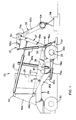
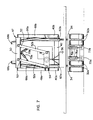
- a vehicle 20 embodying the invention including a reach-and-retract means (i.e. assembly) 22 for reaching, lifting and retracting heavy loads located in front of the vehicle 20.
- the vehicle 20 includes a main frame 24 having side beams 26a and 26b extending in a longitudinal direction substantially over the length of the vehicle 20.
- an operator's cab 28 Supported on the main frame 24 toward the rear of the vehicle 20 is an operator's cab 28. It should be noted that the front of the vehicle 20 is defined herein as the general location where the load is located for lifting, while the operator's cab 28 is near the rear of the vehicle 20. Additionally, for ease of understanding herein, components, subassemblies and the like which have a symmetrical counterpart on an opposite side are numbered such that from the perspective of the driver (i.e. looking forward from the cab) the right side is denoted by the lower case letter "a" and the left side by the lower case "b.”
- each support point is preferably arranged as a dual-wheel system, having a wheel pair with conventional air-inflated tires mounted thereon.
- the vehicle 20 is intended to be completely self-propelled.
- the front wheels 32a, 32b are preferably driven through a suitable gear train and transmission in a conventional manner to a self-contained engine operated from the operator's cab 28.
- the rear wheel pair is coupled to a conventional steering mechanism also controlled from the cab 28. Nevertheless, it can be readily appreciated that such a vehicle 20 could, if desired, be towed in a tractor-trailer arrangement.
- the vehicle 20 includes a load carrying portion for stacking loads thereon such as a load carrying platform 34 disposed above and substantially behind the centerline (i.e., axle) defined by its front tires 32a, 32b.
- a load carrying portion for stacking loads thereon such as a load carrying platform 34 disposed above and substantially behind the centerline (i.e., axle) defined by its front tires 32a, 32b.
- the load carrying portion may be arranged as a unitary surface across the front of vehicle or as separate platforms above each tire, however it is important that the load carrying portion be disposed behind the front axle 33 (i.e., inboard of the wheelbase) such that the weight of stacked loads increases, rather than decreases, the moment counteracting tipping of the vehicle 20.
- the platform 34 is preferably supplemented with an upright back guard 36 to prevent loads from being retracted too far where it might damage the vehicle 20, particularly the several hydraulic cylinders and their associated supply and return lines.
- the centerline of the front tires 32a, 32b acts as the balancing point, or tipping fulcrum during transporting operations, and because the load-carrying platform 34 is substantially behind the front axle 33, the center of gravity of the load is shifted to the vehicle side of the tipping fulcrum so that the vehicle 20 is capable of transporting a substantial amount of weight without tipping and without carrying excess ballast.
- the greater the load stacked upon the platform 34 the greater the moment counteracting tipping, since the weight of the load adds to the weight of the vehicle 20.
- the vehicle 20 of the present invention both acts as a lifting vehicle and as a transport vehicle that carries a load upon its frame. Additionally, by utilizing the platform 34 to carry loads, the vehicle 20 is able to transport an aggregate load substantially greater than the maximum weight that the vehicle 20 can lift without tipping.
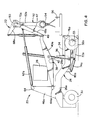
- the vehicle 20 For lifting loads, the vehicle 20 includes a lift means arranged as an H-shaped lift frame 38 including a pair of longitudinally extending lift arms 40a-40b rigidly connected together near their centers by a stabilizing crossbeam 42.
- the lift frame 38 is attached to the main frame 24 near the rear of the vehicle 20, with each lift arm being pivotably connected at transversely aligned points via a pivot pin 44a, 44b or the like projecting from a support 46a, 46b mounted on each side of the main frame 24 near the rear of the vehicle 20.
- a reach-and-retract assembly 22 is pivotally coupled to the lift arms 40a, 40b at their vertically displaceable ends, i.e., at the front of the H-shaped lift frame 38.
- the reach-and-retract assembly 22 includes at least one articulated load support element for connecting a load thereto.
- the load support element comprises a generally rigid tilt frame 47 including a right and left pair of upright members 48a, 48b pivotably coupled by pins 49 at their lower ends to the corresponding right and left lift arms 40a, 40b adjacent their vertically displaceable ends.
- the two upright members 48a, 48b are arranged to pivot in the same plane as the plane in which the lift arms 40a and 40b are upwardly rotated.
- the pivot pins 49 where the lift arms 40a, 40b and upright members 48a, 48b are coupled essentially constitutes an elbow joint, with the upright members 48a, 48b effectively acting to extend and retract the length of the lift arms 40a, 40b in a bendable fashion.
- a cylindrically-shaped crossbeam is pivotably coupled to act as a transverse support element 50 for suspending a swing frame assembly 52 therefrom.
- the swing frame includes right and left depending strut members 52a and 52b coupled to the transverse support element 50.
- the swing frame 52 is rigidly coupled to the transverse support element 50 with respect to longitudinal movement, such that if the transverse support element 50 is rotated around its axis, the swing frame 52 will likewise be rotated and therefore swing up and down vertically according to the amount the transverse support crossbeam 50 is rotated.
- the right and left strut members 52a, 52b are coupled to the transverse support element 50 in a manner that allows a lateral swinging movement relative to the support element 50.
- the swing frame 52 is laterally adjustable relative to the main frame 24, i.e., it can shift either to the left or to the right. As a result, loads which are lifted other than at their lateral centers are maneuverable in the transverse direction prior to stacking upon the stacking platform 34 of the vehicle 20.
- a crossbeam 54 Transversely connected between the lower or depending ends of the boom members 52a, 52b is a crossbeam 54 for holding means for securing a load, i.e., a lifting device 56 such as an electromagnet, a clamping tong assembly or the like.
- the crossbeam 54 is preferably arranged as a universal joint to hold the lifting device both longitudinally and transversely level regardless of the orientation of the strut members 52a, 52b, i.e., their vertical angle relative to the ground or their lateral angle.
- the lifting device 56 is designed to be interchangeable depending on the type of load to be secured.
- a clamping tong assembly having at least one pair of tongs actuated by a hydraulic cylinder serves as the lifting device 56.
- Fig. 9b illustrates a projecting prong useful for lifting coils or the like by inserting the projecting member through a hollow center prior to lifting.
- Fig. 9c illustrates a conventional forklift type of lifting device 56.
- the strut members may alternatively support a number of various mechanisms for supporting the lifting devices 56.
- Fig. 11a illustrates a transverse support member 80 wherein a projecting prong acts as the lifting device 56.
- the transverse support member 80 is pivotally connected to the strut members 52a and 52b at pins 81.
- the same transverse support member 80 can alternatively support an actuable tong assembly acting as the lifting device 56.
- the transverse support member 80 is pivotally connected to the strut members 52a and 52b at pins 81, while the tong assembly is pivotally coupled to transverse support member 80 at pins 82.
- Clamping cylinders 83 are actuated to open and close the pairs of tongs 84, 85.
- an inverted V-shaped transverse support member 84 is utilized to support an electromagnet acting as the lifting device 56.
- the support member 84 is pivotally connected to the strut members 52a and 52b at pins 81.
- the inverted V-shaped support member 84 is utilized to elevate the electromagnet as close as possible to the strut members 52a and 52b such that highly stacked loads can be vertically cleared.
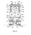
- Fig. 11d illustrates two separate prongs pivotally connected to strut members 52a and 52b at pins 81a and 81b. In this manner, two coils or the like can be simultaneously secured for lifting, as illustrated in Fig. 12 and described in more detail hereinbelow.
- a right and left pair of hydraulic lifting cylinders 60a and 60b are trunnion mounted to the corresponding right and left lift arms 40a, 40b of the lift frame 38 near the centrally located crossbeam 42.
- the pistons of the lifting cylinders 60a, 60b are pivotably mounted to the sides of the main frame 24.
- a right and left pair of hydraulic cylinders 62a, 62b are connected at their piston ends to the upright members 48a, 48b near their upper ends.
- the opposite ends of these reach-and-retract cylinders 62a, 62b are coupled to the upper ends of the main frame supports 46a, 46b via a rotatable common shaft 64 (see Fig. 10).
- the extension and retraction of the reach-and retract cylinders 62a, 62b control the angle between each upright member 48a, 48b of the tilt frame 48 and its corresponding longitudinally extending lift arm 40a, 40b. As a result, they effectively extend and retract the vertical and longitudinal dimensions of the lift frame 38, primarily in order to stack and remove loads from the load carrying platform 34.
- a pair of hydraulic cylinders 66a, 66b are coupled to the transverse support element 50 through a pair of substantially rearwardly projecting arms 68a, 68b rigidly connected thereto.
- the arms 68a, 68b act as a pair of levers for turning the transverse support element 50 thereby controlling the angle of the depending swing frame assembly 52.
- the reach-and-retract capability of the unit is enhanced by the swinging of the swing frame assembly 52, as well as the height that a load can be lifted. This feature provides added flexibility since the lifting, reaching, and retracting capabilities are not exclusively controlled by the lift frame 38 and the angle of the tilt frame 48 and upright members 48a, 48b, but also by the swinging of the swing frame assembly 52.
- a pair of lateral control cylinders 70a, 70b are provided.
- the pistons of these cylinders 79a, 79b are individually connected to the right and left strut members 52a, 52b, while their opposite ends are connected to the transverse support element 50.
- the cylinders 70a, 70b are arranged such that when both are partially extended a substantially equal amount, the swing frame assembly 52 is substantially perpendicular to the transverse support element 50. As illustrated in Fig.
- the lower ends of the strut members 52a and 52b can be separated such that both are free to move in a lateral direction relative to each other.
- each strut member 52a and 52b is laterally shifted an independent amount.
- the operator has the capability of separating or bringing together two separate loads, in addition to being able to shift both loads in the same lateral direction.
- the separate dual prongs 56a and 56b Fig. 11d
- coils having large outer diameters or otherwise having their inner diameters separated by a relatively wide lateral distance can be simultaneously lifted by separating the prongs an appropriate amount.
- the vehicle 20 includes outrigger means for varying the effective longitudinal length of the vehicle 20 to provide a longer effective moment arm.
- the preferred embodiment includes adjustable outriggers 72a, 72b for extending the effective length of the vehicle 20 to make it more difficult for the vehicle 20 to tip over, particularly when reaching far in front of itself to lift a heavy load, and because little or no additional ballast is necessary due to the stacking of loads behind the front axle 33 as described hereinbefore.
- the outriggers 72a, 72b are disposed on opposite sides of the vehicle 20 to the inside of the front wheels 32a, 32b.
- a pair of first hydraulic cylinders 74a, 74b are connected to the main frame 24 at supports 80a and 80b and are pivotally coupled at their piston ends to the outrigger runners 72a, 72b to control the longitudinal extension and retraction of the outrigger members 72a, 72b.
- a second pair of hydraulic cylinders 76a, 76b are provided to controllably force the outrigger members 72a, 72b into engagement with the ground.
- pivoting links 78a and 78b are provided to couple the pivotable connections to the main frame 24, preferably adjacent the support platform 34.
- the outrigger cylinders 76a, 76b When the outrigger cylinders 76a, 76b are extended such that the outrigger members 72a, 72b contact the ground, the balancing point or tipping fulcrum shifts from the centerline of the axle 33 to the outrigger members 72a, 72b, effectively increasing the length of the moment arm of the vehicle 20 and decreasing the moment arm of the load.
- the weight of the vehicle 20 with the increased effective length creates an increased counterbalancing moment and a decreased tipping moment and thus the amount of weight that the vehicle 20 can lift without tipping is greatly increased.
- the length can be extended further when reaching further.
- the effective length of the vehicle can be increased even further for heavier and more remotely positioned loads, subject only to the capabilities of the hydraulic cylinders and the strength of the metal components. Nevertheless, it can be readily appreciated that due to the nature and location of certain loads the outrigger members 72a, 72b are not always fully extendable, and thus it is valuable to be able to controllably adjust the amount of extension.
- the vehicle 20 In operation, to relocate a load such as steel slabs, the vehicle 20 is first driven to the load and then oriented so that the load is within reach of the lifting device 56. As previously described, the vehicle 20 need not be perfectly positioned as a result of its longitudinal reach-and-retract capabilities in conjunction with its lateral adjustment capabilities.
- the operator determines how to deploy the outriggers 72a, 72b (if at all) in dependence on the load weight and the amount of reach necessary to secure the load as described previously. To this end, the operator extends the right and left outrigger-positioning cylinders 74a, 74b an appropriate amount to move the outrigger members 72a, 72b beyond the front wheels 32a, 32b. Once the desired setting for the outriggers 72a, 72b is reached, the operator extends the outrigger engaging cylinders 76a, 76b to plant the front ends of the outrigger members 72a, 72b into the ground.
- the operator ordinarily controls the lifting cylinders 60a and 60b, the reach-and retract cylinders 62a and 62b and the swing angle control cylinders 66a and 66b as necessary for securing the load to the lifting device 56 at the end of the swing frame assembly 52.
- the actual order and amount of cylinder operations required varies according to the individual application being executed. For example, if the operator is controlling the forklift or coil lifting prong described hereinbefore, the lifting device 56 generally needs to be lowered to an appropriate level prior to moving the device 56 forwardly towards the load. Conversely, the electromagnet or tong assembly needs to be maneuvered above the load prior to lowering for pickup.
- the factors determining the cylinder operations include the initial cylinder positions, the distance the load is behind the vehicle 20, the height of the load, the type of lifting device, the amount of the load that can be lifted at any one time, and so on. It should also be noted that the operator might choose to reposition the vehicle 20 by driving it as necessary, although such movement would require temporarily raising the outriggers 72a and 72b if they have been deployed.
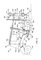
- the operator first elevates the lift frame 38 and angles the boom assembly 52 upwardly to a level sufficient to clear the load in the vertical direction. Once cleared, the reach-and-retract cylinders 62a, 62b are extended to position the electromagnet directly over the load. Subsequently, the lift frame 38 is lowered as far as necessary for the lifting device 56 to contact the load. It can be readily appreciated that since the lift frame 38 actually moves in an arcuate manner, the reach cylinders 62a, 62b are extended an additional amount either before or during the actual lowering of the lift frame 38 to compensate for the slight longitudinal movement that results. In any case, the load contacting position is illustrated in Figs. 1 and 3. Indeed, it should be noted that the vehicle 20 is capable of lifting loads below ground level if necessary.
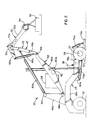
- Fig. 2 shows the load being raised to a maximum vertical position, far beyond what is necessary for stacking the load upon the stacking platform 34 of the vehicle 20 but nevertheless useful for placing or removing loads from highly stacked positions.
- the operator then retracts the reach-and-retract assembly 22 by retracting cylinders 62a and 62b. This brings the load into the proper longitudinal position. Subsequently, the lift frame 38 is lowered as needed by retracting cylinders 60a, 60b until the slab rests just above the platform 34. If the slab is off-center in the lateral direction, the operator controls the lateral angle of the swing frame assembly 52 by operating the lateral boom-angle adjusting cylinders 70a and 70b. As described hereinbefore, this shifts the load to the left or right in a controllable amount. The operator then lowers the slab as needed, for example by lowering the lift frame 38 while making fine adjustments to other cylinders as necessary.
- the electromagnet When the slab is properly positioned, the electromagnet is ordinarily deenergized and the load is released. Nevertheless, it should be noted that merely retracting the load such that its center of gravity is inside of the wheelbase is sufficient for increasing the counterbalancing moment and decreasing the tipping moment, even if the load is not released onto the frame. Thus, some of the advantages are achieved by the retract capabilities of the invention even without stacking the load upon the frame when transporting a load.
- the slab is stacked behind the front axle 33 of the vehicle 20, i.e., inside the wheelbase.
- the weight to the vehicle side of the fulcrum is increased. This prevents tipping during transporting operations when the outrigger members 72a, 72b are raised.
- another slab may be lifted and stacked atop the first slab as shown in Fig. 10. Accordingly, the vehicle 20 can transport more weight than the electromagnet and the rest of the lifting mechanism can handle at any one time.
- the vehicle 20 is driven to transport the load to a desired location, where the load is ordinarily removed in the reverse manner.
- a vehicle has been provided for reaching, lifting, retracting, stacking and carrying loads. Because the vehicle includes the capability of utilizing its lifting and retracting mechanism for carrying or stacking a load behind the centerline of the front tires, the amount of weight that the vehicle can transport without tipping is increased. Loads having a weight exceeding the capacity of a single lifting operation can also be transported apart from the lifting mechanism.
- the vehicle of the present invention is able to reach and stack loads located substantially away from the vehicle. Nevertheless, without requiring undue vehicle length or weight or excess ballast, while reaching and lifting maximum loads the vehicle does not tip.
- the high-capacity lift vehicle is also adapted to operate with interchangeable types of lifting devices. Additionally, the vehicle includes means for adjusting the lateral position of the lifting mechanism or of a lifted load.
Landscapes
- Engineering & Computer Science (AREA)
- Mechanical Engineering (AREA)
- Transportation (AREA)
- Structural Engineering (AREA)
- Civil Engineering (AREA)
- Life Sciences & Earth Sciences (AREA)
- Geology (AREA)
- Forklifts And Lifting Vehicles (AREA)
- Jib Cranes (AREA)
- Handcart (AREA)
Claims (12)
- Véhicule (20) de manutention de charge, comprenant un châssis principal (24) ayant plusieurs roues (30, 32) supportant le châssis principal (24) et délimitant l'empâtement du véhicule, un dispositif de levage comprenant un châssis (38) de levage qui pivote sur le châssis principal (24), et un dispositif moteur (60a, 60b) destiné à soulever et abaisser par pivotement le châssis de levage (38) par rapport au châssis principal (24), un dispositif (22) d'avance et de recul comprenant un châssis basculant articulé (47) raccordé de manière pivotante sur le châssis de levage (38) et un châssis de pivotement articulé (52) raccordé de manière pivotante sur le châssis basculant (47), un dispositif de fixation et de libération de charge (56) porté par le châssis pivotant (52) et destiné à raccorder une charge à celui-ci, un dispositif moteur d'articulation comprenant un dispositif moteur de basculement (62a, 62b) destiné à faire pivoter le châssis de basculement (47) par rapport au châssis de levage (38) et un dispositif moteur de pivotement (66a, 66b) destiné à faire pivoter le châssis pivotant (52) vers l'extérieur par rapport au châssis de basculement (47) pour la fixation ou la libération d'une charge disposée à l'extérieur du châssis principal (24) et de l'empâtement et à faire pivoter le châssis pivotant (52) vers l'intérieur par rapport au châssis de basculement (47) pour le transport de la charge vers l'intérieur de l'empâtement, le châssis pivotant (52) comprenant au moins un bras pivotant (68a) qui dépasse de façon générale vers l'arrière, le dispositif moteur de pivotement (66a, 66b) comporte au moins un vérin hydraulique (66a) interconnecté entre le bras pivotant (68a) et le châssis de basculement (47),
caractérisé en ce que le châssis pivotant (52) comporte une partie transversale (50) montée sur le châssis basculant (47) et destinée à présenter un mouvement de pivotement sur celui-ci autour d'un axe transversal horizontal de façon générale, le bras pivotant (68a) est raccordé à la partie transversale (50) afin qu'il donne un mouvement de pivotement à celle-ci et résiste au mouvement de pivotement de celle-ci, et comprend au moins une jambe de force (52a) qui s'étend de façon générale vers le bas et qui est raccordée à la partie transversale (50) pour le support du dispositif (56) de fixation de charge en permettant un mouvement de pivotement latéral autour d'un axe longitudinal de façon générale et pratiquement perpendiculaire à l'axe transversal, et comprenant un dispositif moteur de décalage (70a, 70b) destiné à décaler latéralement l'extrémité suspendue de la jambe de force (52a) autour de l'axe longitudinal. - Véhicule de manutention de charge selon la revendication 1, dans lequel le châssis principal (24) comporte une partie (34) destinée à supporter et transporter une charge à l'intérieur de façon générale de l'empâtement, séparée du dispositif de levage (38) et du dispositif d'avance et de recul (47), le dispositif de levage (38) et le dispositif d'avance et de recul (47) étant destinés à placer une charge sur la partie (34) de transport de charge du châssis principal (24) ou à retirer une telle charge de cette partie.
- Véhicule de manutention de charge selon la revendication 2, dans lequel les roues comprennent au moins une paire de roues avant (32a, 32b) qui supportent le châssis principal (24) près de son extrémité avant, les roues avant (32a, 32b) ayant chacune un essieu (33) et la partie (34) de transport de charge du châssis principal (24) est disposée de façon générale en arrière des essieux (33) des roues avant.
- Véhicule de manutention de charge selon la revendication 3, comprenant un dispositif (72a, 72b) à arc-boutant fixé au châssis principal (24) et ayant une partie destinée à être au contact du sol pour encaisser au moins une partie de la charge des roues avant (32a, 32b) et un dispositif de manoeuvre (76a, 76b) destiné à mettre sélectivement la partie d'arc-boutant (72a, 72b) au contact du sol.
- Véhicule de manutention de charge selon la revendication 4, dans lequel le dispositif à arc-boutant (72a, 72b) est fixé au châssis principal (24) afin que la partie d'arc-boutant puisse s'allonger et se rétrécir longitudinalement, et comprenant un dispositif moteur d'extension (74a, 74b) destiné à allonger et raccourcir sélectivement la partie d'arc-boutant par rapport à un emplacement qui se trouve à l'extérieur des roues avant (32a, 32b), et comprenant un dispositif (78a, 78b) coopérant avec le dispositif de manoeuvre (76a, 76b) et destiné à supporter le dispositif à arc-boutant (72a, 72b) afin qu'il assure un allongement et un raccourcissement pratiquement longitudinaux lorsque le dispositif moteur (74a, 74b) d'extension est commandé sélectivement.
- Véhicule de manutention de charge selon la revendication 1, dans lequel le châssis principal (24) comprend un élément de support (46a, 46b) qui dépasse vers le haut, et un dispositif moteur de basculement (62a, 62b) comprend au moins un vérin hydraulique raccordé entre l'élément de support (46a, 46b) et le châssis de basculement (47) entre ses extrémités, avec une disposition pratiquement parallèle au châssis de levage (38).
- Véhicule de manutention de charge selon la revendication 1, dans lequel le dispositif moteur (60a, 60b) de soulèvement et d'abaissement du châssis de levage (38) comprend au moins un vérin hydraulique dont le piston ou le cylindre est raccordé au châssis principal (24) et le cylindre ou le piston est raccordé au châssis de levage (38) entre ses extrémités.
- Véhicule de manutention de charge selon la revendication 1, dans lequel le dispositif de fixation et de libération de charge (56) comprend au moins une fourche disposée en direction pratiquement longitudinale par rapport au véhicule.
- Véhicule de manutention de charge selon la revendication 1, dans lequel le dispositif de fixation et de libération de charge (56) comprend un électro-aimant.
- Véhicule de manutention de charge selon la revendication 1, dans lequel le dispositif de fixation et de libération de charge (56) comprend un ensemble à doigts manoeuvrables, l'ensemble à doigts comprenant au moins un organe de manoeuvre de doigts et deux doigts dépassant vers le bas destinés à saisir et transporter une charge.
- Véhicule de manutention de charge selon la revendication 1, dans lequel le dispositif de fixation et de libération de charge (56) comprend au moins une griffe dépassant en direction pratiquement longitudinale par rapport au véhicule.
- Véhicule de manutention de charge selon la revendication 1, dans lequel le dispositif de fixation et de libération de charge (56) comprend deux griffes (56a, 56b) qui s'étendent en direction pratiquement longitudinale par rapport au véhicule et qui comportent un dispositif de décalage latéral (70a, 70b) de chacune des griffes indépendamment de l'autre.
Applications Claiming Priority (3)
| Application Number | Priority Date | Filing Date | Title |
|---|---|---|---|
| US08/078,607 US5437531A (en) | 1993-06-16 | 1993-06-16 | Vehicle for reaching, lifting, retracting, stacking and carrying loads |
| US78607 | 1993-06-16 | ||
| PCT/US1994/006674 WO1994029211A1 (fr) | 1993-06-16 | 1994-06-14 | Vehicule a auto-chargement et a fleche articulee |
Publications (3)
| Publication Number | Publication Date |
|---|---|
| EP0703871A1 EP0703871A1 (fr) | 1996-04-03 |
| EP0703871A4 EP0703871A4 (fr) | 1996-05-29 |
| EP0703871B1 true EP0703871B1 (fr) | 1999-09-01 |
Family
ID=22145127
Family Applications (1)
| Application Number | Title | Priority Date | Filing Date |
|---|---|---|---|
| EP94919484A Expired - Lifetime EP0703871B1 (fr) | 1993-06-16 | 1994-06-14 | Vehicule a auto-chargement et a fleche articulee |
Country Status (7)
| Country | Link |
|---|---|
| US (1) | US5437531A (fr) |
| EP (1) | EP0703871B1 (fr) |
| JP (1) | JPH08511488A (fr) |
| AU (1) | AU680922B2 (fr) |
| CA (1) | CA2165430A1 (fr) |
| DE (1) | DE69420407D1 (fr) |
| WO (1) | WO1994029211A1 (fr) |
Families Citing this family (23)
| Publication number | Priority date | Publication date | Assignee | Title |
|---|---|---|---|---|
| US5641261A (en) * | 1993-10-18 | 1997-06-24 | Taylor Iron-Machine Works, Inc. | Fork lift truck |
| US5720589A (en) * | 1995-08-16 | 1998-02-24 | Mcneilus Truck And Manufacturing, Inc. | Swivel mounted container holding device |
| US6486787B2 (en) * | 1997-06-15 | 2002-11-26 | Kirow Leipzig Kranbau Eberswalde Ag | Heavy goods vehicle with an overload security device |
| FR2774639B1 (fr) * | 1998-02-09 | 2000-05-12 | Marrel Sa | Dispositif, appareil et procede pour permettre a un vehicule de prendre ou de poser au sol une charge presentant un moyen de prehension a l'avant |
| IT1309918B1 (it) * | 1999-08-05 | 2002-02-05 | Belotti Handling S P A | Veicolo per la movimentazione di coils o bobine, in particolare dilamiera,o simili. |
| JP3828856B2 (ja) * | 2002-10-21 | 2006-10-04 | ヤンマー株式会社 | スキッドステアローダ |
| IE20030193A1 (en) * | 2003-03-14 | 2004-09-22 | Moffett Res & Dev Ltd | A forklift loading support |
| US20050042068A1 (en) * | 2003-08-18 | 2005-02-24 | Ronald Ehmen | Forklift with stabilizing forks |
| DE102004009187A1 (de) * | 2004-02-25 | 2005-09-15 | Daimlerchrysler Ag | Steuerungssystem für ein Gespann |
| US7967158B2 (en) | 2006-10-27 | 2011-06-28 | Manitowoc Crane Companies, Llc | Mobile lift crane with variable position counterweight |
| US20090060685A1 (en) * | 2007-08-30 | 2009-03-05 | Howard Godfrey | All-Terrain Log Forwarder |
| US20090107775A1 (en) * | 2007-10-25 | 2009-04-30 | Automated Ag Systems, Llc | Sod Harvester |
| US20100303596A1 (en) * | 2009-05-29 | 2010-12-02 | Automated Ag Systems, Llc | Bin Carrier System |
| US9278834B2 (en) | 2009-08-06 | 2016-03-08 | Manitowoc Crane Group, LLC | Lift crane with moveable counterweight |
| DE202009017388U1 (de) * | 2009-12-22 | 2011-05-05 | Liebherr-Hydraulikbagger Gmbh | Arbeitsmaschine, insbesondere Bagger |
| FR2981300B1 (fr) * | 2011-10-13 | 2013-12-20 | Aztec | Bati retractable pour vehicule d'entretien de pistes skiables |
| US20140271078A1 (en) * | 2013-03-15 | 2014-09-18 | Rodney Koch | Lift arm structure with an articulated knee portion |
| US10179722B2 (en) | 2014-01-27 | 2019-01-15 | Manitowoc Crane Companies, Llc | Lift crane with improved movable counterweight |
| WO2015113032A1 (fr) | 2014-01-27 | 2015-07-30 | Manitowoc Crane Companies, Llc | Mécanisme d'ajustement de hauteur pour un élément auxiliaire sur une grue |
| US10392773B2 (en) * | 2016-08-17 | 2019-08-27 | Caterpillar Sarl | Linkage assembly for machine |
| US20220250879A1 (en) * | 2019-06-28 | 2022-08-11 | Tadano Ltd. | Work vehicle |
| CN112376866A (zh) * | 2020-11-13 | 2021-02-19 | 上海宝冶集团有限公司 | 大板瓷砖的铺贴工具及其建造方法 |
| AU2022342086A1 (en) * | 2021-09-12 | 2024-04-04 | National Oilwell Varco Norway As | Motion-stabilized crane systems and associated methods |
Family Cites Families (24)
| Publication number | Priority date | Publication date | Assignee | Title |
|---|---|---|---|---|
| US2599991A (en) * | 1950-10-26 | 1952-06-10 | Ole I Hegre | Hydraulic hoist |
| US2998143A (en) * | 1957-05-28 | 1961-08-29 | Hydrauliska Ind Aktiebolaget | Lever beam of a loading apparatus |
| FR1356379A (fr) * | 1963-02-13 | 1964-03-27 | Bennes Marrel | Perfectionnements aux dispositifs de grues mobiles destinés à équiper des camions et autres véhicules analogues |
| US3263834A (en) * | 1963-10-14 | 1966-08-02 | Tendresse Philip E La | Pole carrier |
| US3232460A (en) * | 1964-01-07 | 1966-02-01 | Petersen Ind Inc | Concrete hoisting and placing apparatus |
| FR1418844A (fr) * | 1964-05-21 | 1965-11-26 | Yumbo | Engin de levage fonctionnant en dispositif de chargement, en grue et en excavateur |
| US3253716A (en) * | 1964-06-15 | 1966-05-31 | Stratton Equipment Company | Crane having articulated boom |
| US3342361A (en) * | 1964-10-05 | 1967-09-19 | Thomas N Melin | Pivotal fork assembly for fork-lift trucks |
| US3279622A (en) * | 1964-10-27 | 1966-10-18 | Edgar L Person | Vehicle stabilizing means |
| US3487964A (en) * | 1968-01-24 | 1970-01-06 | Joseph L Riley | Self-loading side loaders |
| US3501035A (en) * | 1968-07-22 | 1970-03-17 | Beloit Corp | Pole grappling apparatus with heel means and lateral stabilizers |
| US3876093A (en) * | 1973-03-09 | 1975-04-08 | Pettibone Corp | Bale handler |
| US3863834A (en) * | 1973-10-09 | 1975-02-04 | Somerville Ind Limited | Tear-Strip for Paperboard Container |
| US3945666A (en) * | 1975-03-17 | 1976-03-23 | Harnischfeger Corporation | Powered outrigger beams having stabilizing spacer pad means |
| FR2339563A1 (fr) * | 1976-01-27 | 1977-08-26 | Ppm Sa | Structure telescopique munie d'un detecteur de la position relative de deux troncons |
| US4163625A (en) * | 1978-02-10 | 1979-08-07 | Lee C. Moore Corporation | Movable working platform for use in racking drill pipe |
| US4236643A (en) * | 1978-09-14 | 1980-12-02 | J. I. Case Company | Vehicle stabilizer assembly |
| SE443749B (sv) * | 1979-04-23 | 1986-03-10 | Dynatrans Ab | Containertruck for upplyftning av en container till lege pa trucken for efterfoljande transport |
| DE2935624C2 (de) * | 1979-09-04 | 1985-10-17 | System Schultheis GmbH & Co, Maschinenfabrik, 6400 Fulda | Kettbaum-Einlegewagen |
| US4424985A (en) * | 1981-09-08 | 1984-01-10 | J. I. Case Company | Outrigger support arrangement |
| US4482285A (en) * | 1982-08-12 | 1984-11-13 | Raygo, Inc. | Load carrier assembly |
| US4632630A (en) * | 1983-05-03 | 1986-12-30 | Koehring Company | Forklift attachment |
| US4762291A (en) * | 1987-06-11 | 1988-08-09 | Sauber Charles J | Self-loading reel trailer |
| US4969789A (en) * | 1988-12-16 | 1990-11-13 | Searle Gregory P | Machine for handling modular building components |
-
1993
- 1993-06-16 US US08/078,607 patent/US5437531A/en not_active Expired - Fee Related
-
1994
- 1994-06-14 DE DE69420407T patent/DE69420407D1/de not_active Expired - Lifetime
- 1994-06-14 EP EP94919484A patent/EP0703871B1/fr not_active Expired - Lifetime
- 1994-06-14 CA CA002165430A patent/CA2165430A1/fr not_active Abandoned
- 1994-06-14 AU AU70606/94A patent/AU680922B2/en not_active Ceased
- 1994-06-14 JP JP7502166A patent/JPH08511488A/ja active Pending
- 1994-06-14 WO PCT/US1994/006674 patent/WO1994029211A1/fr active IP Right Grant
Also Published As
| Publication number | Publication date |
|---|---|
| JPH08511488A (ja) | 1996-12-03 |
| EP0703871A1 (fr) | 1996-04-03 |
| DE69420407D1 (de) | 1999-10-07 |
| US5437531A (en) | 1995-08-01 |
| CA2165430A1 (fr) | 1994-12-17 |
| WO1994029211A1 (fr) | 1994-12-22 |
| EP0703871A4 (fr) | 1996-05-29 |
| AU7060694A (en) | 1995-01-03 |
| AU680922B2 (en) | 1997-08-14 |
Similar Documents
| Publication | Publication Date | Title |
|---|---|---|
| EP0703871B1 (fr) | Vehicule a auto-chargement et a fleche articulee | |
| EP1062119B1 (fr) | Cadre de levage independant a point de pivotement monte sur chassis | |
| EP1558464B1 (fr) | Procede et dispositif de support de charge autoportante sur des chassis de roulement | |
| US6551050B1 (en) | Rolling stabilizer lift attachment | |
| EP3538475B1 (fr) | Unité base destinée à un véhicule | |
| EP0415608A2 (fr) | Chariot élévateur à fourche avec un bras télescopique | |
| US4637770A (en) | Self-equalizing lifting trailer | |
| EP1531141B1 (fr) | Chariot élévateur à fourche transportable | |
| US3762590A (en) | Material lifting and transporting vehicle | |
| US3543957A (en) | Fork lift trucks | |
| US6565307B1 (en) | Transfer machine | |
| US4427334A (en) | Load handling apparatus | |
| US4249854A (en) | Low profile fork lift for mine vehicles | |
| US11440369B2 (en) | Pick and carry crane suspension | |
| US20060263191A1 (en) | Self-propelled working machine | |
| US4729710A (en) | Ladle carrier with laterally shiftable cradle | |
| US4269560A (en) | Steering assembly | |
| US6551051B2 (en) | Grapple skidder | |
| EP0311637B1 (fr) | Ensemble de travail mobile a pieds supports verticalement reglables | |
| US4488848A (en) | Load handling apparatus | |
| US5496146A (en) | Steel slab and coil carrier | |
| US4776748A (en) | Receptacle transporting vehicle | |
| US4101040A (en) | Vehicle for transporting palletized loads | |
| US4601630A (en) | Load handling apparatus | |
| WO2008018840A1 (fr) | Dispositif de manipulation et de levage pour tracteurs |
Legal Events
| Date | Code | Title | Description |
|---|---|---|---|
| PUAI | Public reference made under article 153(3) epc to a published international application that has entered the european phase |
Free format text: ORIGINAL CODE: 0009012 |
|
| 17P | Request for examination filed |
Effective date: 19951106 |
|
| AK | Designated contracting states |
Kind code of ref document: A1 Designated state(s): DE FR GB |
|
| A4 | Supplementary search report drawn up and despatched |
Effective date: 19960404 |
|
| AK | Designated contracting states |
Kind code of ref document: A4 Designated state(s): DE FR GB |
|
| GRAG | Despatch of communication of intention to grant |
Free format text: ORIGINAL CODE: EPIDOS AGRA |
|
| 17Q | First examination report despatched |
Effective date: 19980730 |
|
| GRAG | Despatch of communication of intention to grant |
Free format text: ORIGINAL CODE: EPIDOS AGRA |
|
| GRAH | Despatch of communication of intention to grant a patent |
Free format text: ORIGINAL CODE: EPIDOS IGRA |
|
| GRAH | Despatch of communication of intention to grant a patent |
Free format text: ORIGINAL CODE: EPIDOS IGRA |
|
| GRAA | (expected) grant |
Free format text: ORIGINAL CODE: 0009210 |
|
| AK | Designated contracting states |
Kind code of ref document: B1 Designated state(s): DE FR GB |
|
| PG25 | Lapsed in a contracting state [announced via postgrant information from national office to epo] |
Ref country code: FR Free format text: LAPSE BECAUSE OF FAILURE TO SUBMIT A TRANSLATION OF THE DESCRIPTION OR TO PAY THE FEE WITHIN THE PRESCRIBED TIME-LIMIT Effective date: 19990901 |
|
| REF | Corresponds to: |
Ref document number: 69420407 Country of ref document: DE Date of ref document: 19991007 |
|
| PG25 | Lapsed in a contracting state [announced via postgrant information from national office to epo] |
Ref country code: DE Free format text: LAPSE BECAUSE OF FAILURE TO SUBMIT A TRANSLATION OF THE DESCRIPTION OR TO PAY THE FEE WITHIN THE PRESCRIBED TIME-LIMIT Effective date: 19991202 |
|
| EN | Fr: translation not filed | ||
| PG25 | Lapsed in a contracting state [announced via postgrant information from national office to epo] |
Ref country code: GB Free format text: LAPSE BECAUSE OF NON-PAYMENT OF DUE FEES Effective date: 20000614 |
|
| PLBE | No opposition filed within time limit |
Free format text: ORIGINAL CODE: 0009261 |
|
| STAA | Information on the status of an ep patent application or granted ep patent |
Free format text: STATUS: NO OPPOSITION FILED WITHIN TIME LIMIT |
|
| 26N | No opposition filed | ||
| GBPC | Gb: european patent ceased through non-payment of renewal fee |
Effective date: 20000614 |