EP0702841B1 - Überspannungsableiter - Google Patents
Überspannungsableiter Download PDFInfo
- Publication number
- EP0702841B1 EP0702841B1 EP94916141A EP94916141A EP0702841B1 EP 0702841 B1 EP0702841 B1 EP 0702841B1 EP 94916141 A EP94916141 A EP 94916141A EP 94916141 A EP94916141 A EP 94916141A EP 0702841 B1 EP0702841 B1 EP 0702841B1
- Authority
- EP
- European Patent Office
- Prior art keywords
- housing
- surge arrester
- function block
- electrical surge
- arrester according
- Prior art date
- Legal status (The legal status is an assumption and is not a legal conclusion. Google has not performed a legal analysis and makes no representation as to the accuracy of the status listed.)
- Expired - Lifetime
Links
Images
Classifications
-
- H—ELECTRICITY
- H01—ELECTRIC ELEMENTS
- H01C—RESISTORS
- H01C7/00—Non-adjustable resistors formed as one or more layers or coatings; Non-adjustable resistors made from powdered conducting material or powdered semi-conducting material with or without insulating material
- H01C7/10—Non-adjustable resistors formed as one or more layers or coatings; Non-adjustable resistors made from powdered conducting material or powdered semi-conducting material with or without insulating material voltage responsive, i.e. varistors
- H01C7/12—Overvoltage protection resistors; Arresters
Definitions
- the invention relates to an electrical surge arrester, in particular for medium voltage, with a functional block and a surrounding elastically expandable housing made of an insulating material, in which at least one reinforcing element for mechanical reinforcement is embedded separately from the functional block.
- a surge arrester with an elastically expandable housing is known for example from E 0 233 022.
- a surge arrester is described, in which the functional block is first firmly surrounded with a fiber-reinforced resin and the blank thus produced is introduced into an elastic sleeve. After use, the functional block can hardly be freed from the resin that is firmly attached to it, so that great problems arise with environmentally friendly disposal (cf. specialist article "Disposal and recycling of plastic waste", Bulletin SEV / VSE (1992) 15, July 31).
- An electrical surge arrester with a functional block and an elastic housing made of an insulating material is known from EP 0 545 038 A1. Reinforcing elements in the form of plastic strips or plastic strips are cast into the insulating material housing. It is therefore difficult to separate the reinforcing elements from the housing of the surge arrester when the arrester is disposed of.
- the invention is therefore based on the object of providing an electrical surge arrester which is easy to disassemble and which is made of different materials Have existing parts separated as easily as possible for recycling purposes.
- the object is achieved in that the reinforcing element (s) or both the reinforcing element (s) and the functional block are non-positively held by elastic expansion of the insulating material housing and are / are not integrally connected to it.
- the functional block consisting of the actual diverter elements is, if appropriate, pressed into the housing, like the reinforcing elements, with an elastic expansion of the housing walls and held by the elastic pressure of the housing walls.
- the function block can be easily removed from the housing by elastic expansion of the housing walls.
- the functional block which normally consists of a metal oxide and metal parts, can be disposed of or reused separately from the housing, which consists of an insulating material. Assembly during the manufacture of the arrester is also simplified by simply inserting the functional block into the housing.
- the reinforcing element is functionally and spatially separated from the functional block of the arrester and is embedded in the housing body.
- the functional block itself does not need any mechanical reinforcement, for example in the form of a fiber-reinforced plastic layer, since the metal oxide disks can be glued to one another, for example.
- the housing or the arrester as a whole is given the required mechanical stability by the reinforcing element (s).
- the housing consists of an elastic cast body.
- Such a body is easy and inexpensive to manufacture from elastic material.
- the cast body can be designed to be resilient either through the properties of the material from which it is made or through a specific shape, for example the shape of a bellows.
- the housing advantageously has a first recess for receiving the functional block and a second recess for receiving a reinforcing body.
- Both the functional block and the reinforcing element (s) can be pushed axially out of the corresponding recess for separate disposal.
- the housing has shielding ribs on its outside.
- This known measure for extending the creepage distances on the outside of the housing of an arrester can advantageously be taken in that the shielding ribs are integrated in the housing body.
- a further advantageous embodiment of the invention provides that the housing consists of an optionally filled silicone rubber or ethylene-propylene-diene monomer or a mixture of both substances.
- Silicone rubber and EPDM have excellent mechanical and in particular also dielectric properties and are particularly suitable for use in a surge arrester according to the invention because of their long-term stability, good environmental compatibility and simple processability.
- the invention can also be advantageously configured in that the spaces between the functional block and the housing are largely filled by a partially plastically deformable elastic mass.
- a partially plastically deformable elastic mass can consist, for example, of a material based on silicone.
- a further advantageous embodiment of the invention provides that the functional block is connected at least at one of its ends to a connection contact by a flexible electrical conductor, in particular a metal spring.
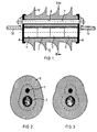
- the surge arrester has a functional block 1 which consists of metal oxide disks 2, 3 which are bonded to one another.
- the functional block 1 is arranged in a recess 4 of a silicone rubber casting 5.
- the recess 4 is smaller in diameter than the diameter of the functional block 1, so that the cast body 5 is elastically expanded when the functional block 1 is inserted and holds the functional block 1 in a force-locking manner.
- the functional block 1 is inserted into the recess 4 of the cast body 5 by expanding the cast body 5 by suitable mechanical means.
- the cast body 5 also has a recess 6 for a reinforcing body 7, which is also held elastically in the recess 6 of the expanded cast body 5.
- the reinforcing element 7, which is formed, for example, from a glass fiber-reinforced plastic rod, holds two metallic connecting plates 8, 9, between which the housing 5 of the surge arrester is clamped.
- the connection plates 8, 9 each carry a connecting bolt 10, 11 for making electrical contact with the surge arrester.
- the surge arrester can be oval in cross-section as shown in Fig. 2, which results in good dielectric strength.
- the cross section can also be designed as shown in Figure 3, resulting in a minimal material consumption for the housing.
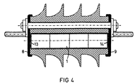
- the surge arrester can also be constructed in such a way that (see FIG. 4) the function block is mechanically and elastically coupled to the connection plates 8, 9 via spiral springs 13, 14 in order to avoid high mechanical loads on the function block 1 during assembly and operation.
Landscapes
- Engineering & Computer Science (AREA)
- Microelectronics & Electronic Packaging (AREA)
- Physics & Mathematics (AREA)
- Electromagnetism (AREA)
- Thermistors And Varistors (AREA)
- Emergency Protection Circuit Devices (AREA)
- Insulators (AREA)
- Dowels (AREA)
Description
- Die Erfindung bezieht sich auf einen elektrischen Überspannungsableiter insbesondere für Mittelspannung mit einem Funktionsblock und einem diesen umgebenden elastisch aufweitbaren Gehäuse aus einem Isolierstoff, in dem getrennt von dem Funktionsblock wenigstens ein Verstärkungselement zur mechanischen Verstärkung eingebettet ist.
- Ein Überspannungsableiter mit einem elastisch aufweitbaren Gehäuse ist beispielsweise aus der E 0 233 022 bekannt. Dort ist ein Überspannungsableiter beschrieben, bei dem der Funktionsblock zunächst fest mit einem faserverstärkten Harz umgeben und der so hergestellte Rohling in eine elastische Hülle eingebracht wird. Nach dem Gebrauch kann der Funktionsblock kaum wieder von dem fest mit ihm verbundenen Harz befreit werden, so daß bei einer umweltschonenden Entsorgung große Probleme entstehen (vgl. Fachartikel "Entsorgung und Verwertung von Kunststoff-Abfällen", Bulletin SEV/VSE (1992) 15, 31.7.).
- Aus der EP 0 545 038 A1 ist ein elektrischer Überspannungsableiter mit einem Funktionsblock und einem elastischen Gehäuse aus einem Isolierstoff bekannt. In das Isolierstoffgehäuse sind Verstärkungselemente in Form von Kunststoffleisten oder Kunststoffbändern eingegossen. Somit ist eine Trennung der Verstärkungselemente von dem Gehäuse des Überspannungsableiters bei der Entsorgung des Ableiters schwierig.
- Der Erfindung liegt daher die Aufgabe zugrunde, einen elektrischen Überspannungsableiter zu schaffen, der leicht demontierbar ist und bei dem sich die aus unterschiedlichem Materialien bestehenden Teile zu Zwecken der Wiederverwertung möglichst weitgehend leicht trennen lassen.
- Die Aufgabe wird erfindungsgemäß dadurch gelöst, daß das/die Verstärkungselement/e oder sowohl das/die Verstärkungselement/e als auch der Funktionsblock durch elastische Aufweitung des Isolierstoffgehäuses kraftschlüssig gehalten und mit diesem nicht stoffschlüssig verbunden ist/sind.
- Der aus den eigentlichen Ableitelementen bestehende Funktionsblock wird gegebenenfalls ebenso wie die Verstärkungselemente in das Gehäuse unter elastischer Aufweitung der Gehäusewände eingedrückt und durch den elastischen Druck der Gehäusewände gehalten. Zur Entsorgung des Überspannungsableiters kann der Funktionsblock leicht wieder aus dem Gehäuse durch elastische Aufweitung der Gehäusewände entnommen werden. Es braucht keine Klebe- oder Schweißverbindung zwischen dem Funktionsblock und dem Gehäuse zu bestehen, so daß der Funktionsblock, der normalerweise aus einem Metalloxid und Metallteilen besteht, getrennt von dem Gehäuse, das aus einem Isolierstoff besteht, entsorgt bzw. wiederverwendet werden kann. Auch die Montage bei der Herstellung des Ableiters ist durch das einfache Einschieben des Funktionsblocks in das Gehäuse vereinfacht.
- Das Verstärkungselement ist funktional und räumlich von dem Funktionsblock des Ableiters getrennt und für sich in dem Gehäusekörper eingebettet. Der Funktionsblock selbst braucht keine mechanische Verstärkung beispielsweise in Form einer faserverstärkten Kunststoffschicht, da die Metalloxidscheiben beispielsweise miteinander verklebt sein können. Dem Gehäuse bzw. dem Ableiter als ganzem wird durch das/die Verstärkungselemente die erforderliche mechanische Stabilität verliehen.
- Eine weitere vorteilhafte Ausgestaltung der Erfindung sieht vor, daß das Gehäuse aus einem elastischen Gußkörper besteht.
- Ein solcher Körper ist aus elastischem Material leicht und kostengünstig herstellbar. Der Gußkörper kann entweder durch die Eigenschaften des Materials aus dem er besteht oder durch eine bestimmte Formgebung, beispielsweise die Form eines Faltenbalges, federelastisch ausgebildet sein.
- Das Gehäuse weist vorteilhaft eine erste Ausnehmung zur Aufnahme des Funktionsblocks und eine zweite Ausnehmung zur Aufnahme eines Verstärkungskörpers auf.
- Diese Ausnehmungen sind dann um so viel kleiner ausgebildet, als der Funktionsblock bzw. der Verstärkungskörper, daß diese nach dem Einschieben in die Ausnehmungen durch die elastische Kraft des aufgeweiteten Gehäuses gehalten werden.
- Sowohl der Funktionsblock als auch das/die Verstärkungselemente können zur getrennten Entsorgung axial aus der entsprechenden Ausnehmung wieder herausgeschoben werden.
- Es kann weiterhin vorteilhaft vorgesehen sein, daß das Gehäuse an seiner Außenseite Schirmrippen trägt.
- Diese bekannte Maßnahme zur Verlängerung der Kriechwege an der Außenseite des Gehäuses eines Ableiters kann vorteilhaft dadurch getroffen werden, daß die Schirmrippen in den Gehäusekörper integriert sind.
- Eine weitere vorteilhafte Ausgestaltung der Erfindung sieht vor, daß das Gehäuse aus einem gegebenenfalls gefüllten Silikongummi oder Ethylen-Propylen-Dien-Monomer oder einer Mischung aus beiden Stoffen besteht.
- Silikongummi und EPDM weisen hervorragende mechanische und insbesondere auch dielektrische Eigenschaften auf und sind wegen ihrer Langzeitstabilität, der guten Umweltverträglichkeit und einfachen Verarbeitbarkeit für die Anwendung bei einem erfindungsgemäßen Überspannungsableiter besonders geeignet.
- Die Erfindung kann außerdem vorteilhaft dadurch ausgestaltet werden, daß die Zwischenräume zwischen dem Funktionsblock und dem Gehäuse durch eine zum Teil plastisch verformbare elastische Masse weitestgehend ausgefüllt sind. Hierdurch wird einerseits das Hineingleiten des Funktionsblocks in die Ausnehmungen in dem Gehäusekörper erleichert, andererseits werden die verbleibenden Zwischenräume ausgefüllt, so daß elektrische Entladungen in etwa entstehenden Hohlräumen zwischen dem Funktionsblock und dem Gehäuse vermieden werden. Die plastisch verformbare elastische Masse kann beispielsweise aus einem Material auf der Basis von Silikon bestehen.
- Eine weitere vorteilhafte Ausgestaltung der Erfindung sieht vor, daß der Funktionsblock an wenigstens einem seiner Enden mit einem Anschlußkontakt durch einen flexiblen elektrischen Leiter, insbesondere eine Metallfeder, verbunden ist.
- Hierdurch wird erreicht, daß sich mechanische Belastungen des Gehäuses nicht oder nur in reduziertem Maß auf den Funktionsblock und seine elektrischen Anschlüsse auswirken.
- Im folgenden wird die Erfindung anhand eines Ausführungsbeispiels in einer Zeichnung gezeigt und anschließend beschrieben.
- Dabei zeigt
- Figur 1 einen schematischen Längsschnitt durch einen erfindungsgemäßen Überspannungsableiter,
- Figur 2 einen Querschnitt des in Figur 1 dargestellten Überspannungsableiters,
- Figur 3 einen weiteren möglichen Querschnitt,
- Figur 4 einen Überspannungsableiter bei dem der Funktionsblock an seinen Enden über Spiralfedern elektrisch angeschlossen ist.
- Der Überspannungsableiter weist einen Funktionsblock 1 auf, der aus miteinander verklebten Metalloxidscheiben 2, 3 besteht. Der Funktionsblock 1 ist in einer Ausnehmung 4 eines Silikongummigußkörpers 5 angeordnet. Die Ausnehmung 4 ist im Durchmesser kleiner als der Durchmesser des Funktionsblocks 1, so daß der Gußkörper 5 bei eingeschobenem Funktionsblock 1 elastisch aufgeweitet ist und den Funktionsblock 1 kraftschlüssig festhält. Das Einführen des Funktionsblocks 1 in die Ausnehmung 4 des Gußkörpers 5 geschieht unter Aufweitung des Gußkörpers 5 durch geeignete mechanische Mittel.
- Der Gußkörper 5 weist außerdem eine Ausnehmung 6 für einen Verstärkungskörper 7 auf, der ebenfalls elastisch in der Ausnehmung 6 des aufgeweiteten Gußkörpers 5 gehalten ist. Durch das Verstärkungselement 7, das beispielsweise aus einem glasfaserverstärkten Kunststoffstab gebildet ist, werden zwei metallische Anschlußplatten 8, 9 gehalten, zwischen denen das Gehäuse 5 des Überspannungsableiters eingespannt ist. Die Anschußplatten 8, 9 tragen jeweils einen Anschlußbolzen 10, 11 zur elektrischen Kontaktierung des Überspannungsableiters.
- Der Überspannungsableiter kann im Querschnitt oval ausgebildet sein wie in Fig. 2 dargestellt, wodurch sich eine gute dielektrische Festigkeit ergibt. Der Querschnitt kann auch wie in Figur 3 dargestellt ausgebildet sein, wobei sich ein minimaler Materialverbrauch für das Gehäuse ergibt.
- Der Überspannungsableiter kann auch so aufgebaut sein, daß (vgl. Figur 4) der Funktionsblock über Spiralfedern 13, 14 mechanisch elastisch an die Anschlußplatten 8, 9 elektrisch leitend angekoppelt ist, um hohe mechanische Belastungen des Funktionsblocks 1 bei Montage und Betrieb zu vermeiden.
Claims (6)
- Elektrischer Überspannungsableiter, insbesondere für Mittelspannung mit einem Funktionsblock (1) und einem diesen umgebenden elastisch auf weitbaren Gehäuse (5) aus einem Isolierstoff, in dem getrennt von dem Funktionsblock (1) wenigstens ein Verstärkungselement (7) zur mechanischen Verstärkung eingebettet ist,
dadurch gekennzeichnet, daß das/die Verstärkungselement/e (7) oder sowohl das/die Verstärkungselement/e (7) als auch der Funktionsblock (1) durch elastische Aufweitung des Isolierstoffgehäuses (5) kraftschlüssig gehalten und mit diesem nicht stoffschlüssig verbunden ist/sind. - Elektrischer Überspannungsableiter nach Anspruch 1,
dadurch gekennzeichnet, daß das Gehäuse (5) aus einem elastischen Gußkörper besteht. - Elektrischer Überspannungsableiter nach Anspruch 1 oder einem der folgenden,
dadurch gekennzeichnet, daß das Gehäuse (5) an seiner Außenseite Schirmrippen (12) trägt. - Elektrischer Überspannungsableiter nach Anspruch 1 oder einem der folgenden,
dadurch gekennzeichnet, daß das Gehäuse (5) aus einem gegebenenfalls gefüllten Silikongummi oder Ethylen-Propylen-Dien-Monomer oder einer Mischung aus beiden Stoffen besteht. - Elektrischer Überspannungsableiter nach Anspruch 1 oder einem der folgenden,
dadurch gekennzeichnet, daß die Zwischenräume zwischen dem Funktionsblock (1) und dem Gehäuse (5) durch eine zum Teil plastisch verformbare elastische Masse weitestgehend ausgefüllt sind. - Elektrischer Überspannungsableiter nach Anspruch 1 oder einen der folgenden,
dadurch gekennzeichnet, daß der Funktionsblock (1) an wenigstens einem seiner Enden mit einem Anschlußkontakt (10, 11) durch einen flexiblen elektrischen Leiter (13, 14), insbesondere eine Metallfeder, verbunden ist.
Applications Claiming Priority (3)
| Application Number | Priority Date | Filing Date | Title |
|---|---|---|---|
| DE4319986 | 1993-06-11 | ||
| DE4319986A DE4319986A1 (de) | 1993-06-11 | 1993-06-11 | Überspannungsableiter |
| PCT/DE1994/000607 WO1994029888A1 (de) | 1993-06-11 | 1994-05-26 | Überspannungsableiter |
Publications (2)
| Publication Number | Publication Date |
|---|---|
| EP0702841A1 EP0702841A1 (de) | 1996-03-27 |
| EP0702841B1 true EP0702841B1 (de) | 1997-03-19 |
Family
ID=6490491
Family Applications (1)
| Application Number | Title | Priority Date | Filing Date |
|---|---|---|---|
| EP94916141A Expired - Lifetime EP0702841B1 (de) | 1993-06-11 | 1994-05-26 | Überspannungsableiter |
Country Status (7)
| Country | Link |
|---|---|
| EP (1) | EP0702841B1 (de) |
| AT (1) | ATE150579T1 (de) |
| DE (2) | DE4319986A1 (de) |
| DK (1) | DK0702841T3 (de) |
| ES (1) | ES2102226T3 (de) |
| NO (1) | NO955001L (de) |
| WO (1) | WO1994029888A1 (de) |
Families Citing this family (4)
| Publication number | Priority date | Publication date | Assignee | Title |
|---|---|---|---|---|
| DE10020129C1 (de) * | 2000-04-14 | 2001-11-15 | Siemens Ag | Baugruppe mit Überspannungsableiter für eine Hochspannungsanlage |
| DE102005017083A1 (de) * | 2005-04-08 | 2006-10-19 | Siemens Ag | Überspannungsableiter mit einem Ableitelement |
| DE102007057265A1 (de) * | 2007-11-26 | 2009-05-28 | Siemens Ag | Isolatoranordnung |
| JP2012512306A (ja) | 2008-12-16 | 2012-05-31 | ダウ グローバル テクノロジーズ エルエルシー | ポリマーによりカプセル化された金属酸化物の不透明化顔料を含む被覆用組成物及びその製造プロセス関連出願に対する相互参照 |
Family Cites Families (17)
| Publication number | Priority date | Publication date | Assignee | Title |
|---|---|---|---|---|
| BE757659A (fr) * | 1969-10-17 | 1971-04-16 | Raychem Corp | Isolants haute tension |
| US3965065A (en) * | 1975-09-08 | 1976-06-22 | Dow Corning Corporation | Method of improving the electrical properties of organopolysiloxane elastomers and compositions therefor |
| CA1137159A (en) * | 1979-04-23 | 1982-12-07 | John P. Dupont | Cap seal for resilient electrical housing |
| IT1195773B (it) * | 1980-04-16 | 1988-10-27 | Dow Corning Ltd | Composizioni organopolisilossaniche formatrici di elastomeri |
| CH666574A5 (de) * | 1984-06-01 | 1988-07-29 | Bbc Brown Boveri & Cie | Ueberspannungsableiter. |
| DE3508030A1 (de) * | 1985-02-07 | 1986-08-07 | BBC Aktiengesellschaft Brown, Boveri & Cie., Baden, Aargau | Verfahren zur herstellung eines ueberspannungsableiters unter verwendung eines aktiven widerstandskoerpers aus einem spannungsabhaengigen widerstandsmaterial auf zno-basis und danach hergestellter ueberspannungsableiter |
| GB8527548D0 (en) * | 1985-11-08 | 1985-12-11 | Raychem Gmbh | Electrical equipment |
| NO171139C (no) * | 1986-01-29 | 1993-01-27 | Bowthorpe Emp Ltd | Elektriske transient stoppere/avledere |
| DE3769955D1 (de) * | 1986-12-12 | 1991-06-13 | Sediver | Verfahren zur herstellung eines blitzableiters und durch dieses verfahren hergestellter blitzableiter. |
| JPS63312602A (ja) * | 1987-06-16 | 1988-12-21 | Ngk Insulators Ltd | 避雷器ユニット |
| SU1578159A1 (ru) * | 1987-11-13 | 1990-07-15 | Предприятие П/Я Г-4430 | Электроизол ционна композици |
| JPH01163925A (ja) * | 1987-12-18 | 1989-06-28 | Ngk Insulators Ltd | 避雷碍子 |
| JPH02148626A (ja) * | 1988-11-30 | 1990-06-07 | Meidensha Corp | 碍管 |
| CA2038720A1 (en) * | 1990-04-02 | 1991-10-03 | Takeshi Kawamura | Arrester |
| SE466176B (sv) * | 1990-05-08 | 1992-01-07 | Asea Brown Boveri | Ventilavledare med ett isolatorhoelje i vilket dragstaenger aer anordnade |
| JP2837978B2 (ja) * | 1991-08-02 | 1998-12-16 | 日本碍子株式会社 | 避雷碍子及びその製造方法 |
| CH682858A5 (de) * | 1991-12-04 | 1993-11-30 | Asea Brown Boveri | Ueberspannungsableiter. |
-
1993
- 1993-06-11 DE DE4319986A patent/DE4319986A1/de not_active Withdrawn
-
1994
- 1994-05-26 EP EP94916141A patent/EP0702841B1/de not_active Expired - Lifetime
- 1994-05-26 AT AT94916141T patent/ATE150579T1/de not_active IP Right Cessation
- 1994-05-26 WO PCT/DE1994/000607 patent/WO1994029888A1/de not_active Ceased
- 1994-05-26 DK DK94916141.8T patent/DK0702841T3/da active
- 1994-05-26 ES ES94916141T patent/ES2102226T3/es not_active Expired - Lifetime
- 1994-05-26 DE DE59402163T patent/DE59402163D1/de not_active Expired - Fee Related
-
1995
- 1995-12-08 NO NO955001A patent/NO955001L/no unknown
Also Published As
| Publication number | Publication date |
|---|---|
| ES2102226T3 (es) | 1997-07-16 |
| NO955001D0 (no) | 1995-12-08 |
| DE4319986A1 (de) | 1994-12-15 |
| ATE150579T1 (de) | 1997-04-15 |
| EP0702841A1 (de) | 1996-03-27 |
| WO1994029888A1 (de) | 1994-12-22 |
| DE59402163D1 (de) | 1997-04-24 |
| NO955001L (no) | 1995-12-08 |
| DK0702841T3 (da) | 1997-10-13 |
Similar Documents
| Publication | Publication Date | Title |
|---|---|---|
| EP1206820B1 (de) | Überspannungsableiter mit einem verspannelement | |
| EP1472761A1 (de) | Rekontaktierbare verbindungsanordnung | |
| DE69111177T2 (de) | Elektrische Lampe. | |
| DE102007003636A1 (de) | Isolierkörper für eine Sammelschienenkupplung und Sammelschienenkupplung | |
| EP0725739A1 (de) | Schleifkontaktelement sowie verfahren zur verbindung eines elektrischen anschlussleiters mit einem schleifkontaktelement | |
| DE10341333B4 (de) | Piezoaktor und Verfahren zum Herstellen eines Piezoaktors | |
| DE3110660A1 (de) | Garnitur fuer das ende eines mittelspannnungs- oder hochspannunskabels | |
| EP0702841A1 (de) | Überspannungsableiter | |
| DE2441517B2 (de) | ||
| DE112018006810T5 (de) | Geräte-transformator vom vakuumkondensator-typ | |
| EP1741162A2 (de) | Elektrische funktionseinheit und verfahren zu deren herstellung | |
| EP0288836B1 (de) | Stosswellengenerator für eine Einrichtung zum berührungslosen Zertrümmern von Konkrementen im Körper eines Lebewesens | |
| DE102009046570A1 (de) | Induktive Anordnung | |
| DE19819693B4 (de) | Federschaltelement mit taktiler Rückmeldung | |
| DE69635541T2 (de) | Heizelement und Verfahren zu dessen Verschliessen | |
| DE102017117636A1 (de) | Steckbare Durchführung | |
| EP0216056B1 (de) | Isolierstützer | |
| EP0222122A2 (de) | Glimmlampeneinsatz für elektrische Installationsgeräte | |
| DE19925191B4 (de) | Kontaktanordnung für Vakuumschalter | |
| DE2939931A1 (de) | Endmuffe fuer kunststoffisolierte geschirmte starkstromkabel | |
| DE102005030046B4 (de) | Elektromechanisches Öffnerrelais und ein Verfahren, mit dem Ströme geschaltet werden können | |
| DE202005012290U1 (de) | Hochspannungselektrodenanordnung | |
| EP0159515B1 (de) | Sicherungsanschlusseinrichtung für gekapselte Mittelspannungsschaltanlagen | |
| EP0822563A2 (de) | Zündgerät für eine Gasentladungslampe in einem Kraftfahrzeug | |
| DE3027097A1 (de) | Vorgefertigter muffenkoerper fuer geschirmte starkstromkabel |
Legal Events
| Date | Code | Title | Description |
|---|---|---|---|
| PUAI | Public reference made under article 153(3) epc to a published international application that has entered the european phase |
Free format text: ORIGINAL CODE: 0009012 |
|
| 17P | Request for examination filed |
Effective date: 19951117 |
|
| AK | Designated contracting states |
Kind code of ref document: A1 Designated state(s): AT DE DK ES FR IT |
|
| 17Q | First examination report despatched |
Effective date: 19960424 |
|
| GRAG | Despatch of communication of intention to grant |
Free format text: ORIGINAL CODE: EPIDOS AGRA |
|
| GRAH | Despatch of communication of intention to grant a patent |
Free format text: ORIGINAL CODE: EPIDOS IGRA |
|
| GRAH | Despatch of communication of intention to grant a patent |
Free format text: ORIGINAL CODE: EPIDOS IGRA |
|
| GRAA | (expected) grant |
Free format text: ORIGINAL CODE: 0009210 |
|
| AK | Designated contracting states |
Kind code of ref document: B1 Designated state(s): AT DE DK ES FR IT |
|
| REF | Corresponds to: |
Ref document number: 150579 Country of ref document: AT Date of ref document: 19970415 Kind code of ref document: T |
|
| REF | Corresponds to: |
Ref document number: 59402163 Country of ref document: DE Date of ref document: 19970424 |
|
| ITF | It: translation for a ep patent filed | ||
| ET | Fr: translation filed | ||
| REG | Reference to a national code |
Ref country code: ES Ref legal event code: FG2A Ref document number: 2102226 Country of ref document: ES Kind code of ref document: T3 |
|
| REG | Reference to a national code |
Ref country code: DK Ref legal event code: T3 |
|
| PLBE | No opposition filed within time limit |
Free format text: ORIGINAL CODE: 0009261 |
|
| STAA | Information on the status of an ep patent application or granted ep patent |
Free format text: STATUS: NO OPPOSITION FILED WITHIN TIME LIMIT |
|
| 26N | No opposition filed | ||
| PGFP | Annual fee paid to national office [announced via postgrant information from national office to epo] |
Ref country code: AT Payment date: 19980506 Year of fee payment: 5 |
|
| PGFP | Annual fee paid to national office [announced via postgrant information from national office to epo] |
Ref country code: ES Payment date: 19980507 Year of fee payment: 5 |
|
| PGFP | Annual fee paid to national office [announced via postgrant information from national office to epo] |
Ref country code: DK Payment date: 19980515 Year of fee payment: 5 |
|
| PGFP | Annual fee paid to national office [announced via postgrant information from national office to epo] |
Ref country code: FR Payment date: 19980529 Year of fee payment: 5 |
|
| PGFP | Annual fee paid to national office [announced via postgrant information from national office to epo] |
Ref country code: DE Payment date: 19980720 Year of fee payment: 5 |
|
| PG25 | Lapsed in a contracting state [announced via postgrant information from national office to epo] |
Ref country code: DK Free format text: LAPSE BECAUSE OF NON-PAYMENT OF DUE FEES Effective date: 19990526 Ref country code: AT Free format text: LAPSE BECAUSE OF NON-PAYMENT OF DUE FEES Effective date: 19990526 |
|
| PG25 | Lapsed in a contracting state [announced via postgrant information from national office to epo] |
Ref country code: ES Free format text: THE PATENT HAS BEEN ANNULLED BY A DECISION OF A NATIONAL AUTHORITY Effective date: 19990527 |
|
| PG25 | Lapsed in a contracting state [announced via postgrant information from national office to epo] |
Ref country code: FR Free format text: LAPSE BECAUSE OF NON-PAYMENT OF DUE FEES Effective date: 20000131 |
|
| PG25 | Lapsed in a contracting state [announced via postgrant information from national office to epo] |
Ref country code: DE Free format text: LAPSE BECAUSE OF NON-PAYMENT OF DUE FEES Effective date: 20000301 |
|
| REG | Reference to a national code |
Ref country code: FR Ref legal event code: ST |
|
| REG | Reference to a national code |
Ref country code: DK Ref legal event code: EBP |
|
| REG | Reference to a national code |
Ref country code: ES Ref legal event code: FD2A Effective date: 20020304 |
|
| PG25 | Lapsed in a contracting state [announced via postgrant information from national office to epo] |
Ref country code: IT Free format text: LAPSE BECAUSE OF NON-PAYMENT OF DUE FEES Effective date: 20050526 |