EP0702227A1 - Terminated cable portion inspection device for stripped terminal crimping machine - Google Patents
Terminated cable portion inspection device for stripped terminal crimping machine Download PDFInfo
- Publication number
- EP0702227A1 EP0702227A1 EP95113921A EP95113921A EP0702227A1 EP 0702227 A1 EP0702227 A1 EP 0702227A1 EP 95113921 A EP95113921 A EP 95113921A EP 95113921 A EP95113921 A EP 95113921A EP 0702227 A1 EP0702227 A1 EP 0702227A1
- Authority
- EP
- European Patent Office
- Prior art keywords
- cable
- sensor
- image pickup
- bidirectional path
- stripped
- Prior art date
- Legal status (The legal status is an assumption and is not a legal conclusion. Google has not performed a legal analysis and makes no representation as to the accuracy of the status listed.)
- Granted
Links
- 238000002788 crimping Methods 0.000 title claims abstract description 72
- 238000007689 inspection Methods 0.000 title claims abstract description 40
- 230000002457 bidirectional effect Effects 0.000 claims abstract description 71
- 238000000149 argon plasma sintering Methods 0.000 claims abstract description 21
- 238000005286 illumination Methods 0.000 claims abstract description 21
- 239000013307 optical fiber Substances 0.000 claims abstract description 14
- 239000011248 coating agent Substances 0.000 claims description 23
- 238000000576 coating method Methods 0.000 claims description 23
- 230000003287 optical effect Effects 0.000 claims description 14
- 238000001514 detection method Methods 0.000 claims description 12
- 230000001788 irregular Effects 0.000 claims description 9
- 230000007723 transport mechanism Effects 0.000 claims description 5
- 239000011347 resin Substances 0.000 description 22
- 229920005989 resin Polymers 0.000 description 22
- 238000009826 distribution Methods 0.000 description 14
- 238000000034 method Methods 0.000 description 6
- 230000002950 deficient Effects 0.000 description 4
- 230000008859 change Effects 0.000 description 3
- 238000009795 derivation Methods 0.000 description 3
- 239000000835 fiber Substances 0.000 description 3
- 230000008569 process Effects 0.000 description 3
- 238000005520 cutting process Methods 0.000 description 2
- 238000005549 size reduction Methods 0.000 description 2
- NIXOWILDQLNWCW-UHFFFAOYSA-N acrylic acid group Chemical group C(C=C)(=O)O NIXOWILDQLNWCW-UHFFFAOYSA-N 0.000 description 1
- 230000015572 biosynthetic process Effects 0.000 description 1
- 239000005337 ground glass Substances 0.000 description 1
- 229910052736 halogen Inorganic materials 0.000 description 1
- 150000002367 halogens Chemical class 0.000 description 1
- 230000006872 improvement Effects 0.000 description 1
- 238000009434 installation Methods 0.000 description 1
- 230000004048 modification Effects 0.000 description 1
- 238000012986 modification Methods 0.000 description 1
- 238000012544 monitoring process Methods 0.000 description 1
- 238000003825 pressing Methods 0.000 description 1
- 238000003672 processing method Methods 0.000 description 1
- 239000010453 quartz Substances 0.000 description 1
- 230000001105 regulatory effect Effects 0.000 description 1
- 230000004044 response Effects 0.000 description 1
- VYPSYNLAJGMNEJ-UHFFFAOYSA-N silicon dioxide Inorganic materials O=[Si]=O VYPSYNLAJGMNEJ-UHFFFAOYSA-N 0.000 description 1
- 238000003786 synthesis reaction Methods 0.000 description 1
Images


Classifications
-
- G—PHYSICS
- G01—MEASURING; TESTING
- G01R—MEASURING ELECTRIC VARIABLES; MEASURING MAGNETIC VARIABLES
- G01R31/00—Arrangements for testing electric properties; Arrangements for locating electric faults; Arrangements for electrical testing characterised by what is being tested not provided for elsewhere
- G01R31/28—Testing of electronic circuits, e.g. by signal tracer
- G01R31/302—Contactless testing
- G01R31/308—Contactless testing using non-ionising electromagnetic radiation, e.g. optical radiation
-
- G—PHYSICS
- G01—MEASURING; TESTING
- G01N—INVESTIGATING OR ANALYSING MATERIALS BY DETERMINING THEIR CHEMICAL OR PHYSICAL PROPERTIES
- G01N21/00—Investigating or analysing materials by the use of optical means, i.e. using sub-millimetre waves, infrared, visible or ultraviolet light
- G01N21/84—Systems specially adapted for particular applications
- G01N21/88—Investigating the presence of flaws or contamination
- G01N21/8806—Specially adapted optical and illumination features
-
- G—PHYSICS
- G01—MEASURING; TESTING
- G01N—INVESTIGATING OR ANALYSING MATERIALS BY DETERMINING THEIR CHEMICAL OR PHYSICAL PROPERTIES
- G01N21/00—Investigating or analysing materials by the use of optical means, i.e. using sub-millimetre waves, infrared, visible or ultraviolet light
- G01N21/84—Systems specially adapted for particular applications
- G01N21/88—Investigating the presence of flaws or contamination
- G01N21/95—Investigating the presence of flaws or contamination characterised by the material or shape of the object to be examined
- G01N21/952—Inspecting the exterior surface of cylindrical bodies or wires
-
- G—PHYSICS
- G01—MEASURING; TESTING
- G01R—MEASURING ELECTRIC VARIABLES; MEASURING MAGNETIC VARIABLES
- G01R31/00—Arrangements for testing electric properties; Arrangements for locating electric faults; Arrangements for electrical testing characterised by what is being tested not provided for elsewhere
- G01R31/28—Testing of electronic circuits, e.g. by signal tracer
- G01R31/302—Contactless testing
- G01R31/304—Contactless testing of printed or hybrid circuits
-
- H—ELECTRICITY
- H01—ELECTRIC ELEMENTS
- H01R—ELECTRICALLY-CONDUCTIVE CONNECTIONS; STRUCTURAL ASSOCIATIONS OF A PLURALITY OF MUTUALLY-INSULATED ELECTRICAL CONNECTING ELEMENTS; COUPLING DEVICES; CURRENT COLLECTORS
- H01R43/00—Apparatus or processes specially adapted for manufacturing, assembling, maintaining, or repairing of line connectors or current collectors or for joining electric conductors
- H01R43/04—Apparatus or processes specially adapted for manufacturing, assembling, maintaining, or repairing of line connectors or current collectors or for joining electric conductors for forming connections by deformation, e.g. crimping tool
- H01R43/048—Crimping apparatus or processes
Definitions
- the present invention relates to a terminated cable portion inspection device for a stripped terminal crimping machine which inspects stripped portions and terminal crimped portions of cables on a bidirectional path along which cable ends are transported.
- Prior art inspection of the stripping conditions of a stripped portion at a cable end in which the coating is removed and the crimping conditions of a terminal crimped portion in which a crimp terminal is crimped to the stripped portion generally involves photographing the stripped portion and terminal crimped portion by an image pickup means such as a television camera and two-dimensional CCD camera, displaying the image photographed by the image pickup means on a monitoring television receiver, processing the image by an image processing means, judging whether or not the stripping and crimping conditions are defective, and displaying the result of judgement by means of a printer or display unit.
- an image pickup means such as a television camera and two-dimensional CCD camera
- a device for such inspection includes a keyboard for operation which is used to input program data and the like required for image processing.
- a stripping portion strips the coating of a cable at a cable end held by a cable holding portion of an arm.
- the arm is pivoted to transport the stripped portion of the cable at the cable end to a terminal crimping portion which in turn crimps a crimp terminal to the stripped portion.
- the arm is then pivoted in the opposite direction to transport the terminal crimped portion of the cable to the stripping position.
- the cable is transported by a predetermined length in a predetermined direction and cut in position. Cables are sequentially subjected to the stripping and terminal crimping by the similar procedure.
- the inspection device for inspecting the stripping and crimping condition is provided on a bidirectional path along which the cable is transported between the stripping portion and terminal crimping portion.
- the inspection device comprises a light source and a television camera on opposite sides of the bidirectional path, and a photosensor including a light projector and a light receiver on opposite sides thereof for detecting a cable photographing timing.
- the photosensor detects the stripped portion and terminal crimped portion passing therethrough, and the light source emits light in response to the detection output of the photosensor.
- the television camera photographs the silhouette image of the stripped and terminal crimped portions, and an image processor captures and processes the silhouette image. In this manner, whether or not the stripping and crimping conditions are defective is judged.
- the inspection device disclosed in Japanese Patent Application Laid-Open No. 61-133844 is of the type wherein the silhouette image is captured, that is, only the outline information of the silhouette is captured.
- the inspection device receives a small amount of image information and is incapable of detecting crimping failures and cores extending off in the silhouette portion, resulting in inaccurate inspection.
- Another inspection device is of the type wherein an object to be inspected is illuminated from the photographing direction of the image pickup means to capture a reflected image for receiving more image information.
- this inspection device is designed to photograph the stationary object to be inspected in a purpose-built space, which requires a wide spacing for installation of a lighting fixture. It is hence difficult to incorporate this inspection device on the bidirectional path between the stripping potion and the terminal crimping portion.
- the inspection device disclosed in Japanese Patent Application Laid-Open No. 61-133844 is of the type such that the single photosensor detects the stripped portion passing through a photographing position of the television camera in one direction (a first direction) along the bidirectional path and the terminal crimped portion passing through a photographing position of the television camera in the opposite direction (a second direction) along the bidirectional path.
- the detection positions are on the side of the cable holding portion of the arm which holds the cable end.
- the cable end hold by the arm in cantilevered fashion is typically transported along the bidirectional path at high speeds of about 2000 mm/s. This causes the distal end of the cable moved in the first direction to deflect slightly rearwardly in the transport direction. On the other hand, the cable end moved in the second direction is weighted with the crimp terminal crimped thereto, causing the distal end of the cable to deflect by a greater amount rearwardly in the opposite transport direction.
- the photographing timings are different between the stripped portion and the terminal crimped portion.
- the cable end transported at high speeds in both directions along the bidirectional path is detected in the same manner by the single photosensor on the side of the cable holding portion of the arm and photographed by the television camera, the images are not stably captured and, in the worst case, a portion to be photographed does not lie within the photographing range of the television camera.
- a stripped terminal crimping machine including a stripping portion for stripping a coating at an end of a cable, a terminal crimping portion for crimping a crimp terminal to the stripped end of the cable, a transport mechanism for transporting the stripped cable end in a first direction along a bidirectional path from an initial position of the bidirectional path to the terminal crimping portion and then transporting the stripped cable end in a second direction along the bidirectional path from the terminal crimping portion to the initial position after crimping of the crimp terminal, and a terminated cable portion inspection device for photographing the cable end transported along the bidirectional path to inspect a stripped portion and a terminal crimped portion of the cable by image processing;
- the terminated cable portion inspection device comprises: an image pickup camera having a high shutter speed; a pair of illuminating portions on opposite sides of a photographing path of the image pickup camera for directing illumination in substantially the same direction as a photographing direction of the image pickup camera toward
- the detection position of the first sensor is positioned in corresponding relation to a passing position of an end of the coating at the stripped cable end
- the detection position of the second sensor is positioned in corresponding relation to a passing position of an intermediate portion of a core crimping portion of the crimped crimp terminal.
- each of the pair of illuminating portions includes: a transmitted light scattering plate between the bidirectional path and each of the light projecting portions projecting the light guided by the optical fiber; and a spacing between each of the light projecting portions and the transmitted light scattering plate for diffusing light.
- each of the pair of illuminating portions includes: a transmitted light scattering plate between the bidirectional path and each of the light projecting portions projecting the light guided by the optical fiber; and a condenser lens between each of the light projecting portions and the transmitted light scattering plate for guiding the light projected from each of the light projecting portions in a direction at right angles to the transmitted light scattering plate.
- the first sensor and the second sensor are positioned so that the cable end is detected by the first sensor and the second sensor when the cable end passes across the optical axis of the image pickup camera.
- the terminated cable portion inspection device further comprises: an irregular reflector plate opposed to the illuminating portions, with the bidirectional path therebetween.
- the illuminating portions for directing illumination in substantially the same direction as the photographing direction of the image pickup camera toward the cable end passing therethrough along the bidirectional path are provided on both sides of the photographing path of the image pickup camera and are elongated in substantially the same direction as the longitudinal direction of the transported cable, thereby ensuring a sufficient brightness.
- the reflected image of the cable end being transported is satisfactorily captured by the image pickup camera having the high shutter speed. This achieves the provision of a great amount of image information, and the inspection using more correct image information.
- the optical fiber is designed to guide the light emitted from the light source to the light projecting portions of the illuminating portions.
- the illuminating portions which are compact in size may be readily incorporated in a small spacing in closer proximity to the bidirectional path of the cable end. This also insures a sufficient brightness and the size reduction of the terminated cable portion inspection device itself incorporated in the stripped terminal crimping machine.
- the detecting position of the first sensor is positioned in corresponding relation to the passing position of the end of the coating at the stripped cable end
- the detecting position of the second sensor is positioned in corresponding relation to the passing position of the intermediate portion of the core crimping portion of the crimped crimp terminal.
- each of the illuminating portions includes the transmitted light scattering plate between the bidirectional path and the light projecting portion projecting the light guided by the optical fiber, and the spacing between the light projecting portion and the transmitted light scattering plate for diffusing light.
- each of the illuminating portions includes the condenser lens between the light projecting portion and the transmitted light scattering plate for guiding the light projected from the light projecting portion in the direction at right angles to the transmitted light scattering plate. This provides illumination of more uniformly scattered light.
- the irregular reflector plate opposed to the illuminating portions, with the bidirectional path therebetween, can irregularly reflect the light from the illuminating portions to function as sub-illumination. This also insures the sufficient brightness.
- a stripped terminal crimping machine like the conventional machine, comprises a stripping portion 3 for stripping a coating 2a at an end of each cable 2 sequentially fed; a terminal crimping portion 6 for crimping a crimp terminal 5 to a stripped portion 4 at the stripped end of the cable 2; a transport arm 7 for holding the cable 2 adjacent one end thereof and serving as a transport mechanism for transporting the end of the cable 2 between the stripping portion 3 and the terminal crimping portion 6 in a reciprocal manner; and a terminated cable portion inspection device 8 located on a bidirectional path P of the end of the cable 2.
- the stripping portion 3 suitably includes a cutting blade for severing the cable 2 and a stripping blade for cutting through the coating 2a, and is controlled to cut and strip the cable 2.
- the terminal crimping portion 6 includes a crimping machine.
- the terminal crimping portion 6 feeds successive crimp terminals 5 one by one to a crimping position in the crimping machine and is controlled to crimp one crimp terminal 5 to the stripped portion 4.
- the transport arm 7 includes a cable clamp portion 7a for releasably holding the cable 2.
- the transport arm 7 is pivoted on a support shaft 9, with the cable 2 held by the cable clamp portion 7a, and is controlled to transport the end of the cable 2 in a reciprocal manner along the bidirectional path P at high speeds (for example, about 2000 mm/s).
- the terminated cable portion inspection device 8 includes an image pickup camera 11, such as a television camera and two-dimensional CCD camera, serving as an image pickup means for photographing the end of the cable 2 transported along the bidirectional path P; an illuminating means 12 for illuminating the end of the cable 2 transported along the bidirectional path P; and a detecting means 13 for detecting the photographing timing of the end of the cable 2 transported along the bidirectional path P.
- an image pickup camera 11 such as a television camera and two-dimensional CCD camera, serving as an image pickup means for photographing the end of the cable 2 transported along the bidirectional path P
- an illuminating means 12 for illuminating the end of the cable 2 transported along the bidirectional path P
- a detecting means 13 for detecting the photographing timing of the end of the cable 2 transported along the bidirectional path P.
- the image pickup camera 11 employs a camera having a superfast shutter function such that the shutter speed is fast (for example, 1/30000 sec.), and is angularly adjustably mounted at a predetermined angle to a mounting bracket 14 on the base of the stripped terminal crimping machine 1.
- the image pickup camera 11 includes a camera body 15, an extension tube 16, and a lens portion 17.
- the illuminating means 12 includes a pair of illuminating portions 20 located on opposite sides of a photographing path 19 of the image pickup camera 11 for directing illumination in substantially the same direction as the photographing direction of the image pickup camera 11 toward the end of the cable 2 passing therethrough along the bidirectional path P, a lamp housing 21 located in a separate position and includes a light source such as a halogen lamp, and optical fibers 22 made of quartz, plastic and the like for guiding the light emitted from light source to the pair of illuminating portions 20.
- a light source such as a halogen lamp
- each optical fibers 22 adjacent the illuminating portions 20 is of a flat and fan-shaped configuration flared gradually toward the end.
- Light projecting portions 23 at the distal ends are held by cuboid-shaped fiber array holders 24 so that they are elongated in substantially the same direction as the longitudinal direction of the cable 2 passing therethrough.
- the fiber array holders 24 are securely mounted in an illumination holder 25.
- the photographing path 19 defined by a rectangular aperture along an optical axis L of the image pickup camera 11 is formed centrally of the illumination holder 25 which in turn includes similarly rectangular illuminating portion mounting apertures 26 on opposite sides of the photographing path 19.
- the fiber array holders 24 are respectively inserted from above into the illuminating portion mounting apertures 26 and securely mounted in the illumination holder 25 with screws and the like.
- Transmitted light scattering plates 27 made of ground glass or acrylic board are securely mounted with screws and the like on the bottom of the illuminating portion mounting apertures 26 suitably spaced apart from the light projecting portions 23 of the optical fibers 22. Spacings surrounded by the light projecting portions 23 and transmitted light scattering plates 27 are defined as spacings 28 for diffusing the light guided by the optical fibers 22.
- the illumination holder 25 is mounted in a predetermined attitude to a mounting bracket 29 on the base of the stripped terminal crimping machine 1.
- the detecting means 13 includes a first sensor 31 for detecting the timing of photographing the end of the cable 2 transported in one direction (a first direction) along the bidirectional path P by the image pickup camera 11, and a second sensor 32 for detecting the timing of photographing the end of the cable 2 transported in the opposite direction (a second direction) along the bidirectional path P by the image pickup camera 11.
- the sensors 31, 32 are mounted to a sensor mounting bracket 33 in a position deviated from the optical axis L of the image pickup camera 11.
- Each of the sensors 31, 32 includes a light projector and a light receiver which are spaced apart in the direction of the optical axis L on opposite sides of the bidirectional path P as shown in Figs. 2 to 4.
- a detecting position Q of the first sensor 31 is located in corresponding relation to the passing position of the end of the coating 2a of the stripped cable 2 as shown in Fig. 6, and a detecting position R of the second sensor 32 is located in corresponding relation to the passing position of an intermediate portion of a core barrel portion 5a serving as a core crimping portion for crimping the crimp terminal 5 to a core portion 2b as shown in Fig. 7.
- the photographing range of the image pickup camera 11 is shown in phantom in Figs. 6 and 7.
- An irregular reflector plate 34 serving as a sub-illuminating means is mounted over the bottom surface of the sensor mounting bracket 33 opposed to the illuminating portions 20 to direct illumination in the direction opposite from the illuminating portions 20 toward the end of the cable 2 passing therethrough along the bidirectional path P.
- the optical axis L of the image pickup camera 11 is slightly inclined toward the end surface at the end of the cable 2 from the direction orthogonal to the longitudinal direction of the cable 2 passing through the photographing position for ease of recognition as shown in Fig. 5.
- the end of the cable 2 fed from a cable feeding portion not shown to the cable clamp portion 7a of the transport arm 7 is held by the cable clamp portion 7a and subjected to the stripping of the coating 2a in the stripping portion 3.
- the transport arm 7 Upon completion of the stripping, the transport arm 7 is pivoted on the support shaft 9 to transport the stripped portion 4 at the end of the cable 2 in the first direction from an initial position of the bidirectional path P.
- the first sensor 31 detects the end of the cable 2 to actuate a timer, and the image pickup camera 11 is controlled so that the shutter fires when the stripped portion 4 passes through the position of the optical axis L.
- the transport arm 7 is pivoted on the support shaft 9 to transport a terminal crimped portion 36 at the end of the cable 2 in the second direction along the bidirectional path P from the terminal crimping portion 6.
- the second sensor 32 detects the end of the cable 2 to actuate the timer, and the image pickup camera 11 is controlled so that the shutter fires when the terminal crimped portion 36 passes through the position of the optical axis L.
- the cable 2 On arrival at the initial position in the stripping portion 3, the cable 2 is transported by a predetermined length in a predetermined direction and cut in position.
- the stripping and terminal crimping are repeatedly performed on successive cables 2 in sequential order in the same fashion, and the stripped portion 4 and terminal crimped portion 36 of the successive cables 2 are photographed during the transport of the end thereof and subjected to the conventional image processing and judgement whether the stripping and crimping conditions are defective or not.
- a sufficient brightness is ensured by the illuminating portions 20 on opposite sides of the photographing path 19 of the image pickup camera 11 for directing the illumination in substantially the same direction as the photographing direction of the image pickup camera 11 toward the end of the cable 2 passing therethrough along the bidirectional path P and each elongated in substantially the same direction as the longitudinal direction of the transported cable 2.
- This allows the high-shutter-speed image pickup camera 11 to satisfactorily capture the reflected image of the end of the cable 2 moving at high speeds, thereby providing a great amount of image information and achieving inspection using more correct image information and improvement in inspection reliability.
- the light emitted from the light source in the lamp housing 21 located in a vacant spacing in the separate position is designed to be guided to the light projecting portions 23 of the illuminating portions 20 by the optical fibers 22, permitting the illuminating portions 20 which are compact in size to be readily incorporated in a small spacing in the stripped terminal crimping machine 1 in closer proximity to the bidirectional path P of the end of the cable 2. This also insures the sufficient brightness and the size reduction of the terminated cable portion inspection device 8 itself incorporated in the stripped terminal crimping machine 1.
- the detecting position Q of the first sensor 31 is located in corresponding relation to the passing position of the end of the coating 2a at the stripped end of the cable 2, the passage of the end of the cable 2 which might suffer a failure such as disconnection of the core portion 2b is satisfactorily detected.
- the detecting position R of the second sensor 32 is located in corresponding relation to the passing position of the intermediate portion of the core barrel portion 5a of the crimped crimp terminal 5, the detecting position R is a generally intermediate position of the photographing range as shown in Fig. 7, which can effectively solve the yawing problem of the crimp terminal 5. This provides good photographing timing by the image pickup camera 11, whether the cable 2 be transported in the first or second direction along the bidirectional path P, and stabilized image capturing.
- the end of the cable 2 held in cantilevered fashion by the cable clamp portion 7a during the high-speed transport causes the distal end of the stripped portion 4 to deflect slightly rearwardly in the transport direction when transported in the first direction along the bidirectional path P.
- the end of the cable 2 weighted by the crimp terminal 5 crimped thereto when transported in the second direction along the bidirectional path P causes the distal end of the terminal crimped portion 36 to deflect by a greater amount rearwardly in the opposite transport direction.
- the provision of the respective purpose-built first and second sensors 31 and 32 can provide good photographing timing by the image pickup camera 11 and stabilized image capturing.
- the light diffusing spacings 28 between the light projecting portions 23 and the transmitted light scattering plates 27 can produce uniformly scattered light for the end of the cable 2 passing along the bidirectional path P to provide illumination of high brightness. Such a structure that the diffusing spacings 28 are merely provided may reduce the costs.
- Fig. 8 illustrates another preferred embodiment according to the present invention wherein the light projectors and light receivers of the first and second sensors 31 and 32 are opposed to cross the intersection of the bidirectional path P and optical axis L.
- the above described timer control is not required, and the shutter of the image pickup camera 11 fires simultaneously with the detection of the end of the cable 2 by the first and second sensors 31, 32.
- one or more condenser lenses 38 may be suitably provided between the light projecting portion 23 and transmitted light scattering plate 27 to guide the light from the light projecting portion 23 in a direction at right angles to the transmitted light scattering plate 27. This provides illumination of higher brightness by more uniformly scattered light.
- the illuminating portions are mounted in the illuminating portion mounting apertures 26 of the illumination holder 25.
- the illuminating portions 20 may be separately independently mounted to the base of the stripped terminal crimping machine 1.
- FIG. 11 An example of the image of the terminal crimped portion 36 transported in the second direction is shown in Fig. 11.
- the shaded portions of Fig. 11 are specular reflection portions. Specular reflection is also provided in the core portion 2b between a resin barrel portion 5b and the core barrel portion 5a. The specular reflection portions are extracted as shown in Fig. 12.
- bellmouths are formed on opposite ends of the core barrel portion 5a to release the stresses during the crimping of the crimp terminal 5.
- the bellmouths sharpen the boundary between the end of the specular reflection portions in the core barrel portion 5 and the core portion 2b.
- Reference points for the image processing are derived by the image processing means by means of the run-length encoding technique which is based on the derivation of the configuration and the like of the crimp terminal 5 to be processed from the changes in white and black information along one scanning line.
- two linear windows W1, W2 are established in the middle of the image of the specular reflection portions in the core barrel portion 5a as shown in Fig. 13.
- the points a, b, c, d of intersection of the windows W1, W2 and the borders of the specular reflection portions are derived.
- the gradient of the specular reflection portions is determined from the gradient of the line segment ab connecting the points a and b.
- a window W3 is established which extends from the mid-point of the line segment ac or any intermediate point on the line segment ac with a gradient of the line segment ab.
- a point A of change in brightness is derived on the window W3 and serves as one of the reference points required for the image processing.
- other reference points B, C, D, E, F, G, H shown in Fig. 12 are derived.
- the barrel portions 5a and 5b are not completely formed in a cylindrical shape and provide incomplete specular surfaces to cause a geometrically unstable shape of the specular reflection portions. It is hence impracticable to determine the reference points during one process shown in Figs. 13 and 14, and the reference points are in practice determined by repeating the process twice or three times.
- the window W3 is established as shown in Fig. 15 due to a gradient error based on the line segment ab of Fig. 14, a reference point A' is not located at the end of the specular reflection portion.
- the windows W1, W2 are re-established at the positions shifted by several pixels from the derived reference point A' and the similar operation is repeated to derive the point of change in brightness on the window W3.
- the configuration, size and gradient of the crimp terminal 5 are determined on the basis of the reference points A to H, and a judgement is made whether or not the crimping conditions of the crimp terminal 5 are defective on the basis of the position of the end of the coating 2a between the resin barrel portion 5b and core barrel portion 5a and the length of projecting core portion 2b between the core barrel portion 5a and a front end connecting portion.
- the attitude of the crimp terminal 5 need not be completely the same because of the correct derivation of the reference points A to H. This allows an acceptable level of rough arrangement of the crimp terminal 5 to be inspected. A stable image is obtained if the crimp terminal 5 falls within the photographing range of the image pickup camera 11.
- a distribution curve based on an area versus received light intensity histogram for an image of the crimp terminal 5 crimped to a blue cable 2 illuminated by the illuminating means 12 is shown, for example, in Fig. 17A wherein the abscissa is a brightness level indicated by 256 gradations and the ordinate is the area (the number of pixels).
- the region of high brightness level corresponds to a specular reflection region S in the barrel portions 5a, 5b of the crimp terminal 5
- the region of intermediate brightness level corresponds to a resin region T of the coating 2a of the cable 2
- the region of low brightness level corresponds to a non-specular reflection region U of the crimp terminal 5.
- the distribution curve of Fig. 17A based on the area versus received light intensity histogram, there are valleys between the specular reflection region S and resin region T and between the resin region T and non-specular reflection region U.
- FIG. 17B A distribution curve based on an area versus received light intensity histogram for a background image including no crimp terminal 5 is shown in Fig. 17B.
- the irregular reflector plate 34 is selected so that the background region T' is positioned intermediate the specular reflection region S and non-specular reflection region U of Fig. 17A.
- Fig. 17C The synthesis of the distribution curves of Figs. 17A and 17B based on the area versus received light intensity histograms is shown in Fig. 17C.
- Fig. 17C there are peaks in the specular reflection region S, background region T', and non-specular reflection region U, and there are valleys between the regions S and T' and between the regions T' and U, similarly to Fig. 17A.
- a typical distribution curve based on the area versus received light intensity histogram for the crimp terminal 5 is previously determined, and binary levels may be set between the specular reflection region S and background region T' and between the background region T' and non-specular reflection region U, that is, in the valleys of the distribution curve.
- Figs. 18A and 18B Distribution curves based on area versus received light intensity histograms when the cable 2 is white and black are shown in Figs. 18A and 18B, respectively.
- the peak in the resin region T is shifted toward the specular reflection region S as compared with the blue cable (Fig. 17A) and there is a small valley between the regions S and T.
- the black cable the peak in the resin region T is shifted toward the non-specular reflection region U as compared with the blue cable, and the resin region T and non-specular reflection region U overlap so that the distinction therebetween is blurry.
- the binary level may be set between the specular reflection region S and resin region T by regulating the illumination intensity using the diaphragm of the lens of the image pickup camera 11. This allows the setting of two different binary levels, that is, the above stated binary level between the specular reflection region S and resin region T and the binary level between the resin region T and non-specular reflection region U.
- one binary level is reliably set in a wide, distinct valley between the resin and non-specular reflection regions T, U and the specular reflection region S.
- two binary levels may be set for the while cable 2, similar to the blue cable, by previously determining the typical distribution curve based on the area versus received light intensity histogram for the crimp terminal 5.
- the black cable although one binary level may be definitely set on the basis of the distribution curve, another binary level may be readily set in a low brightness level region, if required, on the basis of various distribution curves based on area versus received light intensity histograms.
- the setting of two different binary levels on the basis of the distribution curve based on the area versus received light intensity histogram for the image of the crimp terminal 5 toward which illumination is directed by the illuminating portions 20 and irregular reflector plate 34 in opposite directions insures the detection of the core portion 2b extending off, particularly the core portion 2b extending off sidewise.
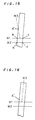
- Fig. 19B is a front view of Fig. 19A which is a plan view.
- the illuminating portions 20 and irregular reflector plate 34 direct illumination in the opposite directions toward the crimp terminal 5 to obtain an image of the crimp terminal 5.
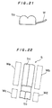
- rectangular windows Wa, Wb are established on opposite sides of the core barrel portion 5a and rectangular windows Wc, Wd are similarly established on opposite sides of the resin barrel portion 5b.
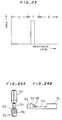
- the distribution curve based on the area versus received light intensity histogram for the windows Wa to Wd is shown in Fig. 23 if the core M does not extend off. In the distribution curve of Fig. 23, there is a peak only in the background region T', and no peaks appear in the regions S and U.
- the core M extending off sidewise from the crimp terminal 5 generates a peak in the region S or U in addition to the peak in the background region T' in the distribution curve for any of the windows Wa to Wd.
- the binary processing is performed on the brightness of each pixel in each of the windows Wa to Wd on the basis of the binary levels set between the regions S an T' and between regions T' and U, and the presence of a pixel having a brightness higher than the higher binary level between the regions S and T' and a pixel having a brightness lower than the lower binary level between the regions T' and U is detected, thereby detecting the core M extending off sidewise from the crimp terminal 5 in any direction.
- failures may be detected as a result of the image processing, for example, the above stated core extending-off failure, a so-called pressing failure in which the resin barrel portion 5b is open, and a short core failure in which no end of the core portion 2b extends from the core barrel portion 5a. These failures detected are subjected to suitable corrective actions.
- the image processing of the terminal crimped portion 36 fed in the second direction along the bidirectional path P has been described above, the image processing of the stripped portion 4 fed in the first direction therealong may be similarly performed.
Landscapes
- Physics & Mathematics (AREA)
- General Physics & Mathematics (AREA)
- Engineering & Computer Science (AREA)
- Health & Medical Sciences (AREA)
- Immunology (AREA)
- General Engineering & Computer Science (AREA)
- General Health & Medical Sciences (AREA)
- Analytical Chemistry (AREA)
- Chemical & Material Sciences (AREA)
- Pathology (AREA)
- Life Sciences & Earth Sciences (AREA)
- Biochemistry (AREA)
- Electromagnetism (AREA)
- Toxicology (AREA)
- Computer Vision & Pattern Recognition (AREA)
- Manufacturing & Machinery (AREA)
- Investigating Materials By The Use Of Optical Means Adapted For Particular Applications (AREA)
- Manufacturing Of Electrical Connectors (AREA)
Abstract
Description
- The present invention relates to a terminated cable portion inspection device for a stripped terminal crimping machine which inspects stripped portions and terminal crimped portions of cables on a bidirectional path along which cable ends are transported.
- Prior art inspection of the stripping conditions of a stripped portion at a cable end in which the coating is removed and the crimping conditions of a terminal crimped portion in which a crimp terminal is crimped to the stripped portion generally involves photographing the stripped portion and terminal crimped portion by an image pickup means such as a television camera and two-dimensional CCD camera, displaying the image photographed by the image pickup means on a monitoring television receiver, processing the image by an image processing means, judging whether or not the stripping and crimping conditions are defective, and displaying the result of judgement by means of a printer or display unit.
- A device for such inspection includes a keyboard for operation which is used to input program data and the like required for image processing.
- This type of inspection device is disclosed in, for example, Japanese Patent Application Laid-Open No. 61-133844 (1986). In this disclosure, a stripping portion strips the coating of a cable at a cable end held by a cable holding portion of an arm. The arm is pivoted to transport the stripped portion of the cable at the cable end to a terminal crimping portion which in turn crimps a crimp terminal to the stripped portion. The arm is then pivoted in the opposite direction to transport the terminal crimped portion of the cable to the stripping position. The cable is transported by a predetermined length in a predetermined direction and cut in position. Cables are sequentially subjected to the stripping and terminal crimping by the similar procedure.
- The inspection device for inspecting the stripping and crimping condition is provided on a bidirectional path along which the cable is transported between the stripping portion and terminal crimping portion.
- The inspection device comprises a light source and a television camera on opposite sides of the bidirectional path, and a photosensor including a light projector and a light receiver on opposite sides thereof for detecting a cable photographing timing. The photosensor detects the stripped portion and terminal crimped portion passing therethrough, and the light source emits light in response to the detection output of the photosensor. The television camera photographs the silhouette image of the stripped and terminal crimped portions, and an image processor captures and processes the silhouette image. In this manner, whether or not the stripping and crimping conditions are defective is judged.
- However, the inspection device disclosed in Japanese Patent Application Laid-Open No. 61-133844 is of the type wherein the silhouette image is captured, that is, only the outline information of the silhouette is captured. The inspection device receives a small amount of image information and is incapable of detecting crimping failures and cores extending off in the silhouette portion, resulting in inaccurate inspection.
- Another inspection device is of the type wherein an object to be inspected is illuminated from the photographing direction of the image pickup means to capture a reflected image for receiving more image information. However, this inspection device is designed to photograph the stationary object to be inspected in a purpose-built space, which requires a wide spacing for installation of a lighting fixture. It is hence difficult to incorporate this inspection device on the bidirectional path between the stripping potion and the terminal crimping portion.
- Further, the inspection device disclosed in Japanese Patent Application Laid-Open No. 61-133844 is of the type such that the single photosensor detects the stripped portion passing through a photographing position of the television camera in one direction (a first direction) along the bidirectional path and the terminal crimped portion passing through a photographing position of the television camera in the opposite direction (a second direction) along the bidirectional path. The detection positions are on the side of the cable holding portion of the arm which holds the cable end.
- The cable end hold by the arm in cantilevered fashion is typically transported along the bidirectional path at high speeds of about 2000 mm/s. This causes the distal end of the cable moved in the first direction to deflect slightly rearwardly in the transport direction. On the other hand, the cable end moved in the second direction is weighted with the crimp terminal crimped thereto, causing the distal end of the cable to deflect by a greater amount rearwardly in the opposite transport direction.
- Thus the photographing timings are different between the stripped portion and the terminal crimped portion. When the cable end transported at high speeds in both directions along the bidirectional path is detected in the same manner by the single photosensor on the side of the cable holding portion of the arm and photographed by the television camera, the images are not stably captured and, in the worst case, a portion to be photographed does not lie within the photographing range of the television camera.
- According to a first aspect of the present invention, in a stripped terminal crimping machine including a stripping portion for stripping a coating at an end of a cable, a terminal crimping portion for crimping a crimp terminal to the stripped end of the cable, a transport mechanism for transporting the stripped cable end in a first direction along a bidirectional path from an initial position of the bidirectional path to the terminal crimping portion and then transporting the stripped cable end in a second direction along the bidirectional path from the terminal crimping portion to the initial position after crimping of the crimp terminal, and a terminated cable portion inspection device for photographing the cable end transported along the bidirectional path to inspect a stripped portion and a terminal crimped portion of the cable by image processing; the terminated cable portion inspection device comprises: an image pickup camera having a high shutter speed; a pair of illuminating portions on opposite sides of a photographing path of the image pickup camera for directing illumination in substantially the same direction as a photographing direction of the image pickup camera toward the cable end passing therethrough along the bidirectional path, the pair of illuminating portions being elongated in substantially the same direction as a longitudinal direction of the cable; an optical fiber for guiding light emitted from a light source to light projecting portions of the illuminating portions; a first sensor for detecting a timing of photographing the cable end transported in the first direction along the bidirectional path by the image pickup camera; and a second sensor for detecting a timing of photographing the cable end transported in the second direction along the bidirectional path by the image pickup camera, the first sensor and the second sensor being located in positions deviated from an optical axis of the image pickup camera.
- According to a second aspect of the present invention, in a stripped terminal crimping machine including a stripping portion for stripping a coating at an end of a cable, a terminal crimping portion for crimping a crimp terminal to the stripped end of the cable, a transport mechanism for transporting the stripped cable end in a first direction along a bidirectional path from an initial position of the bidirectional path to the terminal crimping portion and then transporting the stripped cable end in a second direction along the bidirectional path from the terminal crimping portion to the initial position after crimping of the crimp terminal, and a terminated cable portion inspection device for photographing the cable end transported along the bidirectional path to inspect a stripped portion and a terminal crimped portion of the cable by image processing; the terminated cable portion inspection device comprises: an image pickup camera having a high shutter speed; a pair of illuminating portions on opposite sides of a photographing path of the image pickup camera for directing illumination in substantially the same direction as a photographing direction of the image pickup camera toward the cable end passing therethrough along the bidirectional path, the pair of illuminating portions being elongated in substantially the same direction as a longitudinal direction of the cable; a first sensor for detecting a timing of photographing the cable end transported in the first direction along the bidirectional path by the image pickup camera; and a second sensor for detecting a timing of photographing the cable end transported in the second direction along the bidirectional path by the image pickup camera, the first sensor and the second sensor being located in positions deviated from an optical axis of the image pickup camera, wherein the detection position of the first sensor is positioned in corresponding relation to a passing position of an end of the coating at the stripped cable end, and the detection position of the second sensor is positioned in corresponding relation to a passing position of an intermediate portion of a core crimping portion of the crimped crimp terminal.
- Preferably, according to a third aspect of the present invention, the detection position of the first sensor is positioned in corresponding relation to a passing position of an end of the coating at the stripped cable end, and the detection position of the second sensor is positioned in corresponding relation to a passing position of an intermediate portion of a core crimping portion of the crimped crimp terminal.
- Preferably, according to a fourth aspect of the present invention, each of the pair of illuminating portions includes: a transmitted light scattering plate between the bidirectional path and each of the light projecting portions projecting the light guided by the optical fiber; and a spacing between each of the light projecting portions and the transmitted light scattering plate for diffusing light.
- Preferably, according to a fifth aspect of the present invention, each of the pair of illuminating portions includes: a transmitted light scattering plate between the bidirectional path and each of the light projecting portions projecting the light guided by the optical fiber; and a condenser lens between each of the light projecting portions and the transmitted light scattering plate for guiding the light projected from each of the light projecting portions in a direction at right angles to the transmitted light scattering plate.
- Preferably, according to a sixth aspect of the present invention, the first sensor and the second sensor are positioned so that the cable end is detected by the first sensor and the second sensor when the cable end passes across the optical axis of the image pickup camera.
- Preferably, according to a seventh aspect of the present invention, the terminated cable portion inspection device further comprises: an irregular reflector plate opposed to the illuminating portions, with the bidirectional path therebetween.
- According to the present invention, the illuminating portions for directing illumination in substantially the same direction as the photographing direction of the image pickup camera toward the cable end passing therethrough along the bidirectional path are provided on both sides of the photographing path of the image pickup camera and are elongated in substantially the same direction as the longitudinal direction of the transported cable, thereby ensuring a sufficient brightness. The reflected image of the cable end being transported is satisfactorily captured by the image pickup camera having the high shutter speed. This achieves the provision of a great amount of image information, and the inspection using more correct image information.
- Further, the optical fiber is designed to guide the light emitted from the light source to the light projecting portions of the illuminating portions. The illuminating portions which are compact in size may be readily incorporated in a small spacing in closer proximity to the bidirectional path of the cable end. This also insures a sufficient brightness and the size reduction of the terminated cable portion inspection device itself incorporated in the stripped terminal crimping machine.
- The detecting position of the first sensor is positioned in corresponding relation to the passing position of the end of the coating at the stripped cable end, and the detecting position of the second sensor is positioned in corresponding relation to the passing position of the intermediate portion of the core crimping portion of the crimped crimp terminal. Such an arrangement provides the good photographing timing by the image pickup camera, whether the cable be transported in the first or second direction along the bidirectional path, and stabilized image capturing.
- Additionally, each of the illuminating portions includes the transmitted light scattering plate between the bidirectional path and the light projecting portion projecting the light guided by the optical fiber, and the spacing between the light projecting portion and the transmitted light scattering plate for diffusing light. Otherwise, each of the illuminating portions includes the condenser lens between the light projecting portion and the transmitted light scattering plate for guiding the light projected from the light projecting portion in the direction at right angles to the transmitted light scattering plate. This provides illumination of more uniformly scattered light.
- The irregular reflector plate opposed to the illuminating portions, with the bidirectional path therebetween, can irregularly reflect the light from the illuminating portions to function as sub-illumination. This also insures the sufficient brightness.
- It is therefore an object of the present invention to provide a terminated cable portion inspection device for a stripped terminal crimping machine which is compact in size and of the type wherein a reflected image is captured.
- It is another object of the invention to provide a terminated cable portion inspection device for a stripped terminal crimping machine which provides good photographing timing of an image pickup camera and stabilized image capturing.
- These and other objects, features, aspects and advantages of the present invention will become more apparent from the following detailed description of the present invention when taken in conjunction with the accompanying drawings.
-
- Fig. 1 schematically illustrates essential portions of a stripped terminal crimping machine according to a preferred embodiment of the present invention;
- Fig. 2 schematically illustrates a terminated cable portion inspection device for the stripped terminal crimping machine according to the preferred embodiment of the present invention;
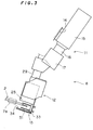
- Fig. 3 is a view in the direction of the arrows III-III of Fig. 2;
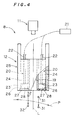
- Fig. 4 illustrates an illuminating means;
- Fig. 5 is a right side view of Fig. 4;
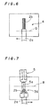
- Fig. 6 illustrates a photographed image of a cable end transported in a first direction;
- Fig. 7 illustrates a photographed image of the cable end transported in a second direction;
- Fig. 8 illustrates another preferred embodiment according to the present invention;
- Fig. 9 illustrates another preferred embodiment according to the present invention;
- Fig. 10 illustrates another preferred embodiment according to the present invention;
- Fig. 11 illustrates an image of the cable end transported in the second direction of the first preferred embodiment;
- Figs. 12-16, 17A-17C, 18A and 18B illustrate image processing of the first preferred embodiment;
- Figs. 19A, 19B, 20 and 21 illustrate operation of the first preferred embodiment;
- Figs. 22 and 23 illustrate image processing of the first preferred embodiment; and
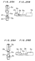
- Figs. 24A, 24B, 25A, 25B, 26A and 26B illustrate operation of the first preferred embodiment.
- Preferred embodiments according to the present invention will now be described with reference to the drawings. Referring to Figs. 1 to 7, a stripped terminal crimping machine 1, like the conventional machine, comprises a stripping portion 3 for stripping a
coating 2a at an end of eachcable 2 sequentially fed; aterminal crimping portion 6 for crimping acrimp terminal 5 to a strippedportion 4 at the stripped end of thecable 2; atransport arm 7 for holding thecable 2 adjacent one end thereof and serving as a transport mechanism for transporting the end of thecable 2 between the stripping portion 3 and theterminal crimping portion 6 in a reciprocal manner; and a terminated cableportion inspection device 8 located on a bidirectional path P of the end of thecable 2. - The stripping portion 3 suitably includes a cutting blade for severing the
cable 2 and a stripping blade for cutting through thecoating 2a, and is controlled to cut and strip thecable 2. - The
terminal crimping portion 6 includes a crimping machine. Theterminal crimping portion 6 feedssuccessive crimp terminals 5 one by one to a crimping position in the crimping machine and is controlled to crimp onecrimp terminal 5 to the strippedportion 4. - The
transport arm 7 includes acable clamp portion 7a for releasably holding thecable 2. Thetransport arm 7 is pivoted on a support shaft 9, with thecable 2 held by thecable clamp portion 7a, and is controlled to transport the end of thecable 2 in a reciprocal manner along the bidirectional path P at high speeds (for example, about 2000 mm/s). - The terminated cable
portion inspection device 8 includes animage pickup camera 11, such as a television camera and two-dimensional CCD camera, serving as an image pickup means for photographing the end of thecable 2 transported along the bidirectional path P; an illuminating means 12 for illuminating the end of thecable 2 transported along the bidirectional path P; and a detectingmeans 13 for detecting the photographing timing of the end of thecable 2 transported along the bidirectional path P. - The
image pickup camera 11 employs a camera having a superfast shutter function such that the shutter speed is fast (for example, 1/30000 sec.), and is angularly adjustably mounted at a predetermined angle to a mountingbracket 14 on the base of the stripped terminal crimping machine 1. Theimage pickup camera 11 includes acamera body 15, anextension tube 16, and alens portion 17. - As shown in Figs. 4 and 5, the illuminating means 12 includes a pair of illuminating
portions 20 located on opposite sides of a photographingpath 19 of theimage pickup camera 11 for directing illumination in substantially the same direction as the photographing direction of theimage pickup camera 11 toward the end of thecable 2 passing therethrough along the bidirectional path P, alamp housing 21 located in a separate position and includes a light source such as a halogen lamp, andoptical fibers 22 made of quartz, plastic and the like for guiding the light emitted from light source to the pair of illuminatingportions 20. - The distal end of each
optical fibers 22 adjacent the illuminatingportions 20 is of a flat and fan-shaped configuration flared gradually toward the end.Light projecting portions 23 at the distal ends are held by cuboid-shapedfiber array holders 24 so that they are elongated in substantially the same direction as the longitudinal direction of thecable 2 passing therethrough. Thefiber array holders 24 are securely mounted in anillumination holder 25. - The photographing
path 19 defined by a rectangular aperture along an optical axis L of theimage pickup camera 11 is formed centrally of theillumination holder 25 which in turn includes similarly rectangular illuminatingportion mounting apertures 26 on opposite sides of the photographingpath 19. Thefiber array holders 24 are respectively inserted from above into the illuminatingportion mounting apertures 26 and securely mounted in theillumination holder 25 with screws and the like. - Transmitted
light scattering plates 27 made of ground glass or acrylic board are securely mounted with screws and the like on the bottom of the illuminatingportion mounting apertures 26 suitably spaced apart from thelight projecting portions 23 of theoptical fibers 22. Spacings surrounded by thelight projecting portions 23 and transmittedlight scattering plates 27 are defined as spacings 28 for diffusing the light guided by theoptical fibers 22. - The
illumination holder 25 is mounted in a predetermined attitude to a mountingbracket 29 on the base of the stripped terminal crimping machine 1. - The detecting means 13 includes a
first sensor 31 for detecting the timing of photographing the end of thecable 2 transported in one direction (a first direction) along the bidirectional path P by theimage pickup camera 11, and asecond sensor 32 for detecting the timing of photographing the end of thecable 2 transported in the opposite direction (a second direction) along the bidirectional path P by theimage pickup camera 11. Thesensors sensor mounting bracket 33 in a position deviated from the optical axis L of theimage pickup camera 11. - Each of the
sensors - A detecting position Q of the
first sensor 31 is located in corresponding relation to the passing position of the end of thecoating 2a of the strippedcable 2 as shown in Fig. 6, and a detecting position R of thesecond sensor 32 is located in corresponding relation to the passing position of an intermediate portion of acore barrel portion 5a serving as a core crimping portion for crimping thecrimp terminal 5 to acore portion 2b as shown in Fig. 7. The photographing range of theimage pickup camera 11 is shown in phantom in Figs. 6 and 7. - An
irregular reflector plate 34 serving as a sub-illuminating means is mounted over the bottom surface of thesensor mounting bracket 33 opposed to the illuminatingportions 20 to direct illumination in the direction opposite from the illuminatingportions 20 toward the end of thecable 2 passing therethrough along the bidirectional path P. The optical axis L of theimage pickup camera 11 is slightly inclined toward the end surface at the end of thecable 2 from the direction orthogonal to the longitudinal direction of thecable 2 passing through the photographing position for ease of recognition as shown in Fig. 5. - In the preferred embodiment of the present invention as above constructed, the end of the
cable 2 fed from a cable feeding portion not shown to thecable clamp portion 7a of thetransport arm 7 is held by thecable clamp portion 7a and subjected to the stripping of thecoating 2a in the stripping portion 3. - Upon completion of the stripping, the
transport arm 7 is pivoted on the support shaft 9 to transport the strippedportion 4 at the end of thecable 2 in the first direction from an initial position of the bidirectional path P. In the course of the transport, thefirst sensor 31 detects the end of thecable 2 to actuate a timer, and theimage pickup camera 11 is controlled so that the shutter fires when the strippedportion 4 passes through the position of the optical axis L. - As the end of the
cable 2 reaches theterminal crimping portion 6, thecrimp terminal 5 is crimped to the strippedportion 4. Upon completion of the crimping, thetransport arm 7 is pivoted on the support shaft 9 to transport a terminal crimped portion 36 at the end of thecable 2 in the second direction along the bidirectional path P from theterminal crimping portion 6. In the course of the transport, thesecond sensor 32 detects the end of thecable 2 to actuate the timer, and theimage pickup camera 11 is controlled so that the shutter fires when the terminal crimped portion 36 passes through the position of the optical axis L. - On arrival at the initial position in the stripping portion 3, the
cable 2 is transported by a predetermined length in a predetermined direction and cut in position. The stripping and terminal crimping are repeatedly performed onsuccessive cables 2 in sequential order in the same fashion, and the strippedportion 4 and terminal crimped portion 36 of thesuccessive cables 2 are photographed during the transport of the end thereof and subjected to the conventional image processing and judgement whether the stripping and crimping conditions are defective or not. - According to the preferred embodiment, as above stated, a sufficient brightness is ensured by the illuminating
portions 20 on opposite sides of the photographingpath 19 of theimage pickup camera 11 for directing the illumination in substantially the same direction as the photographing direction of theimage pickup camera 11 toward the end of thecable 2 passing therethrough along the bidirectional path P and each elongated in substantially the same direction as the longitudinal direction of the transportedcable 2. This allows the high-shutter-speedimage pickup camera 11 to satisfactorily capture the reflected image of the end of thecable 2 moving at high speeds, thereby providing a great amount of image information and achieving inspection using more correct image information and improvement in inspection reliability. - Further, the light emitted from the light source in the
lamp housing 21 located in a vacant spacing in the separate position is designed to be guided to thelight projecting portions 23 of the illuminatingportions 20 by theoptical fibers 22, permitting the illuminatingportions 20 which are compact in size to be readily incorporated in a small spacing in the stripped terminal crimping machine 1 in closer proximity to the bidirectional path P of the end of thecable 2. This also insures the sufficient brightness and the size reduction of the terminated cableportion inspection device 8 itself incorporated in the stripped terminal crimping machine 1. - Since the detecting position Q of the
first sensor 31 is located in corresponding relation to the passing position of the end of thecoating 2a at the stripped end of thecable 2, the passage of the end of thecable 2 which might suffer a failure such as disconnection of thecore portion 2b is satisfactorily detected. Since the detecting position R of thesecond sensor 32 is located in corresponding relation to the passing position of the intermediate portion of thecore barrel portion 5a of the crimpedcrimp terminal 5, the detecting position R is a generally intermediate position of the photographing range as shown in Fig. 7, which can effectively solve the yawing problem of thecrimp terminal 5. This provides good photographing timing by theimage pickup camera 11, whether thecable 2 be transported in the first or second direction along the bidirectional path P, and stabilized image capturing. - The end of the
cable 2 held in cantilevered fashion by thecable clamp portion 7a during the high-speed transport causes the distal end of the strippedportion 4 to deflect slightly rearwardly in the transport direction when transported in the first direction along the bidirectional path P. The end of thecable 2 weighted by thecrimp terminal 5 crimped thereto when transported in the second direction along the bidirectional path P causes the distal end of the terminal crimped portion 36 to deflect by a greater amount rearwardly in the opposite transport direction. However, the provision of the respective purpose-built first andsecond sensors image pickup camera 11 and stabilized image capturing. - The
light diffusing spacings 28 between the light projectingportions 23 and the transmittedlight scattering plates 27 can produce uniformly scattered light for the end of thecable 2 passing along the bidirectional path P to provide illumination of high brightness. Such a structure that the diffusingspacings 28 are merely provided may reduce the costs. - Fig. 8 illustrates another preferred embodiment according to the present invention wherein the light projectors and light receivers of the first and
second sensors image pickup camera 11 fires simultaneously with the detection of the end of thecable 2 by the first andsecond sensors - Referring to Figs. 9 and 10, one or
more condenser lenses 38 may be suitably provided between the light projectingportion 23 and transmittedlight scattering plate 27 to guide the light from thelight projecting portion 23 in a direction at right angles to the transmittedlight scattering plate 27. This provides illumination of higher brightness by more uniformly scattered light. - In the first and second preferred embodiments, the illuminating portions are mounted in the illuminating
portion mounting apertures 26 of theillumination holder 25. However, the illuminatingportions 20 may be separately independently mounted to the base of the stripped terminal crimping machine 1. - The processing of the photographed reflected image is discussed below using the image of the terminal crimped portion 36 transported in the second direction along the bidirectional path P.
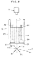
- An example of the image of the terminal crimped portion 36 transported in the second direction is shown in Fig. 11. The shaded portions of Fig. 11 are specular reflection portions. Specular reflection is also provided in the
core portion 2b between aresin barrel portion 5b and thecore barrel portion 5a. The specular reflection portions are extracted as shown in Fig. 12. - In general, bellmouths are formed on opposite ends of the
core barrel portion 5a to release the stresses during the crimping of thecrimp terminal 5. The bellmouths sharpen the boundary between the end of the specular reflection portions in thecore barrel portion 5 and thecore portion 2b. - Reference points for the image processing are derived by the image processing means by means of the run-length encoding technique which is based on the derivation of the configuration and the like of the
crimp terminal 5 to be processed from the changes in white and black information along one scanning line. - Specifically, to detect the reference points required for the image processing, two linear windows W1, W2 are established in the middle of the image of the specular reflection portions in the
core barrel portion 5a as shown in Fig. 13. The points a, b, c, d of intersection of the windows W1, W2 and the borders of the specular reflection portions are derived. The gradient of the specular reflection portions is determined from the gradient of the line segment ab connecting the points a and b. Then, as shown in Fig. 14, a window W3 is established which extends from the mid-point of the line segment ac or any intermediate point on the line segment ac with a gradient of the line segment ab. A point A of change in brightness is derived on the window W3 and serves as one of the reference points required for the image processing. Likewise, other reference points B, C, D, E, F, G, H shown in Fig. 12 are derived. - In practice, the
barrel portions - More specifically, if the window W3 is established as shown in Fig. 15 due to a gradient error based on the line segment ab of Fig. 14, a reference point A' is not located at the end of the specular reflection portion. In this case, the windows W1, W2 are re-established at the positions shifted by several pixels from the derived reference point A' and the similar operation is repeated to derive the point of change in brightness on the window W3.
- In this manner, the repetition of the establishment of the window W3 and derivation of the brightness change point twice or three times can accurately derive the reference point A (Fig. 14).
- After the reference points A to H required for the image processing are derived by the above noted procedure, the configuration, size and gradient of the
crimp terminal 5 are determined on the basis of the reference points A to H, and a judgement is made whether or not the crimping conditions of thecrimp terminal 5 are defective on the basis of the position of the end of thecoating 2a between theresin barrel portion 5b andcore barrel portion 5a and the length of projectingcore portion 2b between thecore barrel portion 5a and a front end connecting portion. - The attitude of the
crimp terminal 5 need not be completely the same because of the correct derivation of the reference points A to H. This allows an acceptable level of rough arrangement of thecrimp terminal 5 to be inspected. A stable image is obtained if thecrimp terminal 5 falls within the photographing range of theimage pickup camera 11. - A distribution curve based on an area versus received light intensity histogram for an image of the
crimp terminal 5 crimped to ablue cable 2 illuminated by the illuminating means 12 is shown, for example, in Fig. 17A wherein the abscissa is a brightness level indicated by 256 gradations and the ordinate is the area (the number of pixels). In Fig. 17A, the region of high brightness level corresponds to a specular reflection region S in thebarrel portions crimp terminal 5, the region of intermediate brightness level corresponds to a resin region T of thecoating 2a of thecable 2, and the region of low brightness level corresponds to a non-specular reflection region U of thecrimp terminal 5. In the distribution curve of Fig. 17A based on the area versus received light intensity histogram, there are valleys between the specular reflection region S and resin region T and between the resin region T and non-specular reflection region U. - A distribution curve based on an area versus received light intensity histogram for a background image including no
crimp terminal 5 is shown in Fig. 17B. There is a peak in a background region T' corresponding to the resin region T. Theirregular reflector plate 34 is selected so that the background region T' is positioned intermediate the specular reflection region S and non-specular reflection region U of Fig. 17A. - The synthesis of the distribution curves of Figs. 17A and 17B based on the area versus received light intensity histograms is shown in Fig. 17C. In Fig. 17C, there are peaks in the specular reflection region S, background region T', and non-specular reflection region U, and there are valleys between the regions S and T' and between the regions T' and U, similarly to Fig. 17A.
- For the
blue cable 2, a typical distribution curve based on the area versus received light intensity histogram for thecrimp terminal 5 is previously determined, and binary levels may be set between the specular reflection region S and background region T' and between the background region T' and non-specular reflection region U, that is, in the valleys of the distribution curve. - Distribution curves based on area versus received light intensity histograms when the
cable 2 is white and black are shown in Figs. 18A and 18B, respectively. With the while cable, the peak in the resin region T is shifted toward the specular reflection region S as compared with the blue cable (Fig. 17A) and there is a small valley between the regions S and T. With the black cable, the peak in the resin region T is shifted toward the non-specular reflection region U as compared with the blue cable, and the resin region T and non-specular reflection region U overlap so that the distinction therebetween is blurry. However, in the case of the white cable, the binary level may be set between the specular reflection region S and resin region T by regulating the illumination intensity using the diaphragm of the lens of theimage pickup camera 11. This allows the setting of two different binary levels, that is, the above stated binary level between the specular reflection region S and resin region T and the binary level between the resin region T and non-specular reflection region U. In the case of the black cable, one binary level is reliably set in a wide, distinct valley between the resin and non-specular reflection regions T, U and the specular reflection region S. - Thus two binary levels may be set for the
while cable 2, similar to the blue cable, by previously determining the typical distribution curve based on the area versus received light intensity histogram for thecrimp terminal 5. For the black cable, although one binary level may be definitely set on the basis of the distribution curve, another binary level may be readily set in a low brightness level region, if required, on the basis of various distribution curves based on area versus received light intensity histograms. - The setting of two different binary levels on the basis of the distribution curve based on the area versus received light intensity histogram for the image of the
crimp terminal 5 toward which illumination is directed by the illuminatingportions 20 andirregular reflector plate 34 in opposite directions insures the detection of thecore portion 2b extending off, particularly thecore portion 2b extending off sidewise. - For example, when the
crimp terminal 5 is crimped to the cable, with one core M extending off over thecore barrel portion 5a as shown in Figs. 19A and 19B, then the extending-off core M reflects light from the illuminatingportions 20 as shown by the arrows of Fig. 20 which is an enlarged sectional view taken along the line X-X' of Fig. 19A. Since this reflection causes partially irregular reflection in the specular reflection portions in thecore barrel portion 5a, the core M extending off over thecore barrel portion 5a is definitely detected by the binary processing using one binary level. Therefore, the core M extending off over thecore barrel portion 5a is detected by the presence of partially irregular reflection in the specular reflection portions in thecore barrel portion 5a. Fig. 19B is a front view of Fig. 19A which is a plan view. - When the core M is extending off sidewise from the
crimp terminal 5 as shown in Fig. 21, the illuminatingportions 20 andirregular reflector plate 34 direct illumination in the opposite directions toward thecrimp terminal 5 to obtain an image of thecrimp terminal 5. On the image of thecrimp terminal 5 as shown in Fig. 22, rectangular windows Wa, Wb are established on opposite sides of thecore barrel portion 5a and rectangular windows Wc, Wd are similarly established on opposite sides of theresin barrel portion 5b. The distribution curve based on the area versus received light intensity histogram for the windows Wa to Wd is shown in Fig. 23 if the core M does not extend off. In the distribution curve of Fig. 23, there is a peak only in the background region T', and no peaks appear in the regions S and U. - The core M extending off sidewise from the
crimp terminal 5 generates a peak in the region S or U in addition to the peak in the background region T' in the distribution curve for any of the windows Wa to Wd. Thus the binary processing is performed on the brightness of each pixel in each of the windows Wa to Wd on the basis of the binary levels set between the regions S an T' and between regions T' and U, and the presence of a pixel having a brightness higher than the higher binary level between the regions S and T' and a pixel having a brightness lower than the lower binary level between the regions T' and U is detected, thereby detecting the core M extending off sidewise from thecrimp terminal 5 in any direction. - As a result of the image processing, it is judged that the crimping conditions of the
crimp terminal 5 are good, when theresin barrel portion 5b grasps thecoating 2a, with thecoating 2a of thecable 2 extending by a suitable length between theresin barrel portion 5b andcore barrel portion 5a of thecrimp terminal 5, and thecore barrel portion 5a grasps thecore portion 2b, with thecore portion 2b slightly exposed between thecore barrel portion 5a and a frontend connecting portion 5c, as shown in Figs. 24A and 24B. - As a result of the image processing, a so-called resin portion crimping failure is judged, when the
coating 2a of thecable 2 does not appear between theresin barrel portion 5b andcore barrel portion 5a of thecrimp terminal 5 and theresin barrel portion 5b grasps the end of thecoating 2a as shown in Figs. 25A and 25B. - As a result of the image processing, a so-called resin engagement failure is judged, when the
core barrel portion 5a of thecrimp terminal 5 grasps the end of thecoating 2a and thecore portion 2b does not appear between theresin barrel portion 5b andcore barrel portion 5a as shown in Figs. 26A and 26B. - Other failures may be detected as a result of the image processing, for example, the above stated core extending-off failure, a so-called pressing failure in which the
resin barrel portion 5b is open, and a short core failure in which no end of thecore portion 2b extends from thecore barrel portion 5a. These failures detected are subjected to suitable corrective actions. - Although the image processing of the terminal crimped portion 36 fed in the second direction along the bidirectional path P has been described above, the image processing of the stripped
portion 4 fed in the first direction therealong may be similarly performed. - In the processing using the photographed reflected image, other image processing methods may be used for quality judgement.
- While the invention has been shown and described in detail, the foregoing description is in all aspects illustrative and not restrictive. It is therefore understood that numerous modifications and variations can be devised without departing from the scope of the invention.
Claims (8)
- In a stripped terminal crimping machine including a stripping portion for stripping a coating at an end of a cable, a terminal crimping portion for crimping a crimp terminal to the stripped end of the cable, a transport mechanism for transporting the stripped cable end in a first direction along a bidirectional path from an initial position of the bidirectional path to the terminal crimping portion and then transporting the stripped cable end in a second direction along the bidirectional path from the terminal crimping portion to the initial position after crimping of the crimp terminal, and a terminated cable portion inspection device for photographing the cable end transported along the bidirectional path to inspect a stripped portion and a terminal crimped portion of the cable by image processing;
said terminated cable portion inspection device comprising:
a image pickup camera having a high shutter speed;
a pair of illuminating portions on opposite sides of a photographing path of said image pickup camera for directing illumination in substantially the same direction as a photographing direction of said image pickup camera toward the cable end passing therethrough along the bidirectional path, said pair of illuminating portions being elongated in substantially the same direction as a longitudinal direction of the cable;
an optical fiber for guiding light emitted from a light source to light projecting portions of said illuminating portions;
a first sensor for detecting a timing of photographing the cable end transported in the first direction along the bidirectional path by said image pickup camera; and
a second sensor for detecting a timing of photographing the cable end transported in the second direction along the bidirectional path by said image pickup camera,
said first sensor and said second sensor being located in positions deviated from an optical axis of said image pickup camera. - In a stripped terminal crimping machine including a stripping portion for stripping a coating at an end of a cable, a terminal crimping portion for crimping a crimp terminal to the stripped end of the cable, a transport mechanism for transporting the stripped cable end in a first direction along a bidirectional path from an initial position of the bidirectional path to the terminal crimping portion and then transporting the stripped cable end in a second direction along the bidirectional path from the terminal crimping portion to the initial position after crimping of the crimp terminal, and a terminated cable portion inspection device for photographing the cable end transported along the bidirectional path to inspect a stripped portion and a terminal crimped portion of the cable by image processing;
said terminated cable portion inspection device comprising:
an image pickup camera having a high shutter speed;
a pair of illuminating portions on opposite sides of a photographing path of said image pickup camera for directing illumination in substantially the same direction as a photographing direction of said image pickup camera toward the cable end passing therethrough along the bidirectional path, said pair of illuminating portions being elongated in substantially the same direction as a longitudinal direction of the cable;
a first sensor for detecting a timing of photographing the cable end transported in the first direction along the bidirectional path by said image pickup camera; and
a second sensor for detecting a timing of photographing the cable end transported in the second direction along the bidirectional path by said image pickup camera,
said first sensor and said second sensor being located in positions deviated from an optical axis of said image pickup camera,
wherein the detection position of said first sensor is positioned in corresponding relation to a passing position of an end of the coating at the stripped cable end, and the detection position of said second sensor is positioned in corresponding relation to a passing position of an intermediate portion of a core crimping portion of the crimped crimp terminal. - The terminated cable portion inspection device of claim 1,
wherein the detection position of said first sensor is positioned in corresponding relation to a passing position of an end of the coating at the stripped cable end, and the detection position of said second sensor is positioned in corresponding relation to a passing position of an intermediate portion of a core crimping portion of the crimped crimp terminal. - The terminated cable portion inspection device of claim 1,
wherein each of said pair of illuminating portions includes:
a transmitted light scattering plate between said bidirectional path and each of said light projecting portions projecting the light guided by said optical fiber; and
a spacing between each of said light projecting portions and said transmitted light scattering plate for diffusing light. - The terminated cable portion inspection device of claim 1,
wherein each of said pair of illuminating portions includes:
a transmitted light scattering plate between said bidirectional path and each of said light projecting portions projecting the light guided by said optical fiber; and
a condenser lens between each of said light projecting portions and said transmitted light scattering plate for guiding the light projected from each of said light projecting portions in a direction at right angles to said transmitted light scattering plate. - The terminated cable portion inspection device of claim 1,
wherein said first sensor and said second sensor are positioned so that the cable end is detected by said first sensor and said second sensor when the cable end passes across the optical axis of said image pickup camera. - The terminated cable portion inspection device of claim 2,
wherein said first sensor and said second sensor are positioned so that the cable end is detected by said first sensor and said second sensor when the cable end passes across the optical axis of said image pickup camera. - The terminated cable portion inspection device of claim 1, further comprising:
an irregular reflector plate opposed to said illuminating portions, with the bidirectional path therebetween.
Applications Claiming Priority (4)
| Application Number | Priority Date | Filing Date | Title |
|---|---|---|---|
| JP6220600A JP3002388B2 (en) | 1994-09-14 | 1994-09-14 | Inspection device for wire processing part in stripping terminal crimping machine |
| JP6220601A JP3002389B2 (en) | 1994-09-14 | 1994-09-14 | Inspection device for wire processing part in stripping terminal crimping machine |
| JP220601/94 | 1994-09-14 | ||
| JP220600/94 | 1994-09-14 |
Publications (2)
| Publication Number | Publication Date |
|---|---|
| EP0702227A1 true EP0702227A1 (en) | 1996-03-20 |
| EP0702227B1 EP0702227B1 (en) | 1998-12-02 |
Family
ID=26523798
Family Applications (1)
| Application Number | Title | Priority Date | Filing Date |
|---|---|---|---|
| EP95113921A Expired - Lifetime EP0702227B1 (en) | 1994-09-14 | 1995-09-05 | Terminated cable portion inspection device for stripped terminal crimping machine |
Country Status (3)
| Country | Link |
|---|---|
| US (1) | US5691763A (en) |
| EP (1) | EP0702227B1 (en) |
| DE (1) | DE69506348T2 (en) |
Cited By (6)
| Publication number | Priority date | Publication date | Assignee | Title |
|---|---|---|---|---|
| EP0718594A3 (en) * | 1994-12-22 | 1998-03-11 | Sumitomo Wiring Systems, Ltd. | Method and device for illumination in terminated cable part inspection device for stripped terminal crimping machine |
| EP1043813A1 (en) * | 1999-04-06 | 2000-10-11 | Harness System Technologies Research, Ltd. | Apparatus for inspecting and manufacturing wire harness |
| EP1391689A1 (en) * | 2002-08-16 | 2004-02-25 | Komax Holding Ag | Apparatus and method for detecting grommets |
| US6738134B2 (en) | 2000-09-28 | 2004-05-18 | Yazaki Corporation | Inspection method and inspection system of a terminal metal fitting |
| WO2014023879A1 (en) * | 2012-08-08 | 2014-02-13 | Clara Vision | Support and picture-taking housing in particular for the monitoring of quality of crimping of electrical cables |
| EP3855359A1 (en) | 2020-01-23 | 2021-07-28 | Schleuniger AG | Cable processing station, cable machine with cable processing stations and computer implemented method |
Families Citing this family (13)
| Publication number | Priority date | Publication date | Assignee | Title |
|---|---|---|---|---|
| US6885463B2 (en) * | 1999-10-28 | 2005-04-26 | Oes, Inc. | Sensor device that provides part quality and profile information |
| US6496271B1 (en) * | 1999-10-28 | 2002-12-17 | Oes, Inc. | Wire and seal profile analyzer |
| US6626711B2 (en) * | 2000-06-12 | 2003-09-30 | Yazaki Corporation | Press-clamping terminal and method of examining press-clamped condition thereof |
| US7963032B2 (en) * | 2006-10-09 | 2011-06-21 | Komax Holding Ag | Method for determining the position of a wire fitting on a wire |
| DE102008006457A1 (en) | 2008-01-29 | 2009-07-30 | Kromberg & Schubert Gmbh & Co. Kg | Electrical conductor i.e. faulty cable in electrical system of vehicle, contacting method, involves bypassing conductor end piece at measuring area of sensor devices and detecting individual lead protruding from cutting surface by devices |
| JP5460527B2 (en) | 2009-11-19 | 2014-04-02 | 新明和工業株式会社 | Coated wire inspection device and wire processing machine equipped with the same |
| RS66875B1 (en) * | 2018-08-13 | 2025-06-30 | Komax Holding Ag | Inspection apparatus for inspecting a cable tip of a cable and method for cleaning |
| CN113574755B (en) | 2018-12-21 | 2023-06-13 | 3M创新有限公司 | Cable preparation system |
| EP3900134A1 (en) | 2018-12-21 | 2021-10-27 | 3M Innovative Properties Company | Electrical power cable preparation system |
| WO2020206627A1 (en) * | 2019-04-10 | 2020-10-15 | 3M Innovative Properties Company | Cable preparation inspection device, system and method |
| JP7140732B2 (en) * | 2019-09-20 | 2022-09-21 | 矢崎総業株式会社 | Appearance inspection device for crimp terminals |
| EP4081756B1 (en) | 2019-12-26 | 2025-10-29 | 3M Innovative Properties Company | Measurement tool for cable-preparation system |
| EP4715373A1 (en) * | 2024-09-23 | 2026-03-25 | Komax Singapore Pte. Ltd. | Cable inspection system |
Citations (4)
| Publication number | Priority date | Publication date | Assignee | Title |
|---|---|---|---|---|
| JPS61133845A (en) * | 1984-12-03 | 1986-06-21 | Shin Meiwa Ind Co Ltd | Crimp terminal grip inspection device |
| JPS61133844A (en) | 1984-12-03 | 1986-06-21 | Shin Meiwa Ind Co Ltd | Inspecting device for compressed part of terminal of terminal compressed wire |
| JPH02189880A (en) * | 1989-01-18 | 1990-07-25 | Shin Meiwa Ind Co Ltd | Crimp contact condition inspecting device for crimped terminal |
| EP0562614A2 (en) * | 1992-03-26 | 1993-09-29 | Sumitomo Wiring Systems, Ltd. | Method and apparatus for inspecting a solderless terminal by image processing |
Family Cites Families (9)
| Publication number | Priority date | Publication date | Assignee | Title |
|---|---|---|---|---|
| US4240110A (en) * | 1978-09-18 | 1980-12-16 | Eastman Kodak Company | Inspection of elongated material |
| US4232336A (en) * | 1978-09-18 | 1980-11-04 | Eastman Kodak Company | Inspection of elongated material |
| US4415926A (en) * | 1982-05-28 | 1983-11-15 | Eastman Kodak Company | Inspection of elongated material |
| GB2128772A (en) * | 1982-10-18 | 1984-05-02 | Philips Electronic Associated | Automatic assembly apparatus |
| US4555799A (en) * | 1983-10-24 | 1985-11-26 | Sumitomo Electric Industries, Ltd. | Method for inspecting crimp bonded terminals |
| US4636847A (en) * | 1985-11-29 | 1987-01-13 | Cabletest International Inc. | Test apparatus |
| US4988202A (en) * | 1989-06-28 | 1991-01-29 | Westinghouse Electric Corp. | Solder joint inspection system and method |
| JP2624054B2 (en) * | 1991-09-19 | 1997-06-25 | 住友電装株式会社 | Wire stripping condition inspection method |
| US5608817A (en) * | 1993-11-18 | 1997-03-04 | Honda Giken Kogyo Kabushiki Kaisha | Optical measuring method |
-
1995
- 1995-09-05 DE DE69506348T patent/DE69506348T2/en not_active Expired - Fee Related
- 1995-09-05 EP EP95113921A patent/EP0702227B1/en not_active Expired - Lifetime
- 1995-09-07 US US08/524,517 patent/US5691763A/en not_active Expired - Fee Related
Patent Citations (4)
| Publication number | Priority date | Publication date | Assignee | Title |
|---|---|---|---|---|
| JPS61133845A (en) * | 1984-12-03 | 1986-06-21 | Shin Meiwa Ind Co Ltd | Crimp terminal grip inspection device |
| JPS61133844A (en) | 1984-12-03 | 1986-06-21 | Shin Meiwa Ind Co Ltd | Inspecting device for compressed part of terminal of terminal compressed wire |
| JPH02189880A (en) * | 1989-01-18 | 1990-07-25 | Shin Meiwa Ind Co Ltd | Crimp contact condition inspecting device for crimped terminal |
| EP0562614A2 (en) * | 1992-03-26 | 1993-09-29 | Sumitomo Wiring Systems, Ltd. | Method and apparatus for inspecting a solderless terminal by image processing |
Non-Patent Citations (2)
| Title |
|---|
| PATENT ABSTRACTS OF JAPAN vol. 010, no. 327 (P - 513) 7 November 1986 (1986-11-07) * |
| PATENT ABSTRACTS OF JAPAN vol. 014, no. 467 (E - 0989) 11 October 1990 (1990-10-11) * |
Cited By (7)
| Publication number | Priority date | Publication date | Assignee | Title |
|---|---|---|---|---|
| EP0718594A3 (en) * | 1994-12-22 | 1998-03-11 | Sumitomo Wiring Systems, Ltd. | Method and device for illumination in terminated cable part inspection device for stripped terminal crimping machine |
| EP1043813A1 (en) * | 1999-04-06 | 2000-10-11 | Harness System Technologies Research, Ltd. | Apparatus for inspecting and manufacturing wire harness |
| US6738134B2 (en) | 2000-09-28 | 2004-05-18 | Yazaki Corporation | Inspection method and inspection system of a terminal metal fitting |
| EP1391689A1 (en) * | 2002-08-16 | 2004-02-25 | Komax Holding Ag | Apparatus and method for detecting grommets |
| WO2014023879A1 (en) * | 2012-08-08 | 2014-02-13 | Clara Vision | Support and picture-taking housing in particular for the monitoring of quality of crimping of electrical cables |
| EP3855359A1 (en) | 2020-01-23 | 2021-07-28 | Schleuniger AG | Cable processing station, cable machine with cable processing stations and computer implemented method |
| WO2021148981A1 (en) | 2020-01-23 | 2021-07-29 | Schleuniger Ag | Cable processing station, cable machine with cable processing stations, and computer-implemented method |
Also Published As
| Publication number | Publication date |
|---|---|
| US5691763A (en) | 1997-11-25 |
| DE69506348D1 (en) | 1999-01-14 |
| EP0702227B1 (en) | 1998-12-02 |
| DE69506348T2 (en) | 1999-09-09 |
Similar Documents
| Publication | Publication Date | Title |
|---|---|---|
| US5691763A (en) | Terminated cable portion inspection device for stripped terminal crimping machine | |
| US5619792A (en) | Method and device for illumination in terminated cable part inspection device for stripped terminal crimping machine | |
| EP0501683A2 (en) | Technique for enhanced two-dimensional imaging | |
| JP2001255281A (en) | Inspection device | |
| US5377278A (en) | Method and apparatus for inspecting a solderless terminal by image processing | |
| JP3935048B2 (en) | Covered wire inspection equipment | |
| JP3002389B2 (en) | Inspection device for wire processing part in stripping terminal crimping machine | |
| JP2505969B2 (en) | Covered wire peeling inspection device | |
| TW434658B (en) | Automatic wafer mapping in a wet environment on a wafer cleaner | |
| JP2001141662A (en) | Method and apparatus for detecting flaw of transparent plate-shaped object | |
| US6128034A (en) | High speed lead inspection system | |
| JP3002388B2 (en) | Inspection device for wire processing part in stripping terminal crimping machine | |
| JPH02189880A (en) | Crimp contact condition inspecting device for crimped terminal | |
| JP3287789B2 (en) | Inspection device for insulated wire with cap | |
| JPH0756446B2 (en) | Inspection method for rod-shaped protrusions | |
| JPS61213709A (en) | Electronic component appearance inspection method | |
| JP2001513594A (en) | Method and apparatus for position detection and / or coplanarity inspection and / or separation inspection of device terminals | |
| JPH07117391B2 (en) | Inspection device for caulking part of terminal in lighting lamp | |
| JPH023121B2 (en) | ||
| JP2600500B2 (en) | Glass pipe end chamfering inspection equipment | |
| JPH05249043A (en) | Illuminating method in compression-bonded terminal image processing inspection | |
| JP2000193511A (en) | Liquid level detector for ampule | |
| JPH06242020A (en) | Surface defect inspection device | |
| JPH0310064B2 (en) | ||
| KR200203480Y1 (en) | A test apparatus for printed circuit board |
Legal Events
| Date | Code | Title | Description |
|---|---|---|---|
| PUAI | Public reference made under article 153(3) epc to a published international application that has entered the european phase |
Free format text: ORIGINAL CODE: 0009012 |
|
| AK | Designated contracting states |
Kind code of ref document: A1 Designated state(s): DE GB |
|
| 17P | Request for examination filed |
Effective date: 19960201 |
|
| 17Q | First examination report despatched |
Effective date: 19970321 |
|
| GRAG | Despatch of communication of intention to grant |
Free format text: ORIGINAL CODE: EPIDOS AGRA |
|
| GRAG | Despatch of communication of intention to grant |
Free format text: ORIGINAL CODE: EPIDOS AGRA |
|
| GRAH | Despatch of communication of intention to grant a patent |
Free format text: ORIGINAL CODE: EPIDOS IGRA |
|
| GRAH | Despatch of communication of intention to grant a patent |
Free format text: ORIGINAL CODE: EPIDOS IGRA |
|
| GRAA | (expected) grant |
Free format text: ORIGINAL CODE: 0009210 |
|
| AK | Designated contracting states |
Kind code of ref document: B1 Designated state(s): DE GB |
|
| REF | Corresponds to: |
Ref document number: 69506348 Country of ref document: DE Date of ref document: 19990114 |
|
| PLBE | No opposition filed within time limit |
Free format text: ORIGINAL CODE: 0009261 |
|
| STAA | Information on the status of an ep patent application or granted ep patent |
Free format text: STATUS: NO OPPOSITION FILED WITHIN TIME LIMIT |
|
| 26N | No opposition filed | ||
| PGFP | Annual fee paid to national office [announced via postgrant information from national office to epo] |
Ref country code: DE Payment date: 20010828 Year of fee payment: 7 |
|
| PGFP | Annual fee paid to national office [announced via postgrant information from national office to epo] |
Ref country code: GB Payment date: 20010905 Year of fee payment: 7 |
|
| REG | Reference to a national code |
Ref country code: GB Ref legal event code: IF02 |
|
| PG25 | Lapsed in a contracting state [announced via postgrant information from national office to epo] |
Ref country code: GB Free format text: LAPSE BECAUSE OF NON-PAYMENT OF DUE FEES Effective date: 20020905 |
|
| PG25 | Lapsed in a contracting state [announced via postgrant information from national office to epo] |
Ref country code: DE Free format text: LAPSE BECAUSE OF NON-PAYMENT OF DUE FEES Effective date: 20030401 |
|
| GBPC | Gb: european patent ceased through non-payment of renewal fee |
Effective date: 20020905 |