EP0701065A2 - Pressure actuator for high pressure hydraulics - Google Patents
Pressure actuator for high pressure hydraulics Download PDFInfo
- Publication number
- EP0701065A2 EP0701065A2 EP95112898A EP95112898A EP0701065A2 EP 0701065 A2 EP0701065 A2 EP 0701065A2 EP 95112898 A EP95112898 A EP 95112898A EP 95112898 A EP95112898 A EP 95112898A EP 0701065 A2 EP0701065 A2 EP 0701065A2
- Authority
- EP
- European Patent Office
- Prior art keywords
- proviso
- use according
- pressure cylinder
- end components
- tube
- Prior art date
- Legal status (The legal status is an assumption and is not a legal conclusion. Google has not performed a legal analysis and makes no representation as to the accuracy of the status listed.)
- Granted
Links
Images

Classifications
-
- F—MECHANICAL ENGINEERING; LIGHTING; HEATING; WEAPONS; BLASTING
- F15—FLUID-PRESSURE ACTUATORS; HYDRAULICS OR PNEUMATICS IN GENERAL
- F15B—SYSTEMS ACTING BY MEANS OF FLUIDS IN GENERAL; FLUID-PRESSURE ACTUATORS, e.g. SERVOMOTORS; DETAILS OF FLUID-PRESSURE SYSTEMS, NOT OTHERWISE PROVIDED FOR
- F15B15/00—Fluid-actuated devices for displacing a member from one position to another; Gearing associated therewith
- F15B15/08—Characterised by the construction of the motor unit
- F15B15/14—Characterised by the construction of the motor unit of the straight-cylinder type
- F15B15/1423—Component parts; Constructional details
- F15B15/1433—End caps
-
- F—MECHANICAL ENGINEERING; LIGHTING; HEATING; WEAPONS; BLASTING
- F15—FLUID-PRESSURE ACTUATORS; HYDRAULICS OR PNEUMATICS IN GENERAL
- F15B—SYSTEMS ACTING BY MEANS OF FLUIDS IN GENERAL; FLUID-PRESSURE ACTUATORS, e.g. SERVOMOTORS; DETAILS OF FLUID-PRESSURE SYSTEMS, NOT OTHERWISE PROVIDED FOR
- F15B15/00—Fluid-actuated devices for displacing a member from one position to another; Gearing associated therewith
- F15B15/08—Characterised by the construction of the motor unit
- F15B15/14—Characterised by the construction of the motor unit of the straight-cylinder type
- F15B15/1423—Component parts; Constructional details
- F15B15/1428—Cylinders
-
- F—MECHANICAL ENGINEERING; LIGHTING; HEATING; WEAPONS; BLASTING
- F15—FLUID-PRESSURE ACTUATORS; HYDRAULICS OR PNEUMATICS IN GENERAL
- F15B—SYSTEMS ACTING BY MEANS OF FLUIDS IN GENERAL; FLUID-PRESSURE ACTUATORS, e.g. SERVOMOTORS; DETAILS OF FLUID-PRESSURE SYSTEMS, NOT OTHERWISE PROVIDED FOR
- F15B15/00—Fluid-actuated devices for displacing a member from one position to another; Gearing associated therewith
- F15B15/08—Characterised by the construction of the motor unit
- F15B15/14—Characterised by the construction of the motor unit of the straight-cylinder type
- F15B15/149—Fluid interconnections, e.g. fluid connectors, passages
-
- F—MECHANICAL ENGINEERING; LIGHTING; HEATING; WEAPONS; BLASTING
- F15—FLUID-PRESSURE ACTUATORS; HYDRAULICS OR PNEUMATICS IN GENERAL
- F15B—SYSTEMS ACTING BY MEANS OF FLUIDS IN GENERAL; FLUID-PRESSURE ACTUATORS, e.g. SERVOMOTORS; DETAILS OF FLUID-PRESSURE SYSTEMS, NOT OTHERWISE PROVIDED FOR
- F15B2215/00—Fluid-actuated devices for displacing a member from one position to another
- F15B2215/30—Constructional details thereof
- F15B2215/305—Constructional details thereof characterised by the use of special materials
Definitions
- the invention relates to an actuator of the high-pressure hydraulic system, which has at least one pressure cylinder in which at least one metallic actuating piston with a piston rod is guided.
- the pressure cylinder is generally provided with end components which are pushed into the pressure cylinder, held by tie rods and sealed against the pressure cylinder.
- one of the end components is a closed component and the other has a bore in which the piston rod is guided in a sealed manner.
- the piston can also have a piston rod on both sides, which are guided in both end components.
- several pistons can also be provided in the pressure cylinder. It can be in the actuator z. B. act as a single or double acting actuator.
- the piston of such an actuator generally has molded-on metallic piston rings or polymeric sliding bands which effect the guidance.
- a soft seal can be arranged between the piston rings.
- high pressure denotes a hydrostatic pressure of over 100 bar, for. B. from 400 to 500 bar.
- the pressure cylinder is a component made of steel, which has a wall thickness corresponding to the pressure of the high-pressure medium. This makes the actuator a heavy weight unit.
- the invention is based on the technical problem of creating an actuating cylinder of the design described at the outset and of the purpose described at the outset, which is much lighter with the same power and the same pressure as the high-pressure hydraulics and can therefore be used in particular in aircraft, in ships and other vehicles without that a disturbing increase in weight would have to be accepted.
- the subject of the invention is the use of a composite unit consisting of a metallic liner in the form of a circular cylindrical inner tube and a fiber-reinforced plastic tube placed thereon as a pressure cylinder of an actuator of the high-pressure hydraulics, which has at least one such pressure cylinder, into which a metallic actuating piston with a piston rod works in the inner tube, with the proviso that the pressure cylinder has metallic end components which are fitted with a cylindrical fitting into the metallic inner liner of the pressure cylinder and are connected to it in a sealed manner, and project with collar formations above the pressure cylinder, at least one end component having a bore and the piston rod being guided therein , with the proviso that the supply and discharge of the high pressure medium takes place via channels in the end components and with the proviso that the two end components are connected by tie rods, which are held in the collar training.
- Actuators that have a pressure cylinder made of a metallic liner and a casing made of fiber-proven plastic are known (WO 93/23675).
- the metallic liner and the casing are not designed as circular cylindrical tubes. The manufacture is therefore complex.
- Actuators are also known which have a pressure cylinder made of an inner tube and an outer tube (WO 91/11319), both of which consist of fiber-proven plastic. These actuators are not very suitable for high pressure hydraulics.
- the pressure cylinder consists of a thin-walled inner tube and a fiber-reinforced plastic tube can exist if the requirements described in claim 1 are realized and if the connection of the pressure cylinder to the end components and the adjustment of the tie rods stabilizes the pressure cylinder against deformations caused by high pressure medium.
- the high-pressure medium in the outer tube which is connected to the end components, would easily produce tensile forces running in the circumferential direction, the high-pressure medium increasing the diameter of the outer tube. This would result in an impairment of the tightness between the piston and the inner tube.
- this disruptive deformation can be prevented if a fiber composite outer tube with a high modulus of elasticity is used in the circumferential direction in the manner described.
- the outer jacket is under slight tension when the high-pressure medium is not present.
- the pretension can also be set up without a force-locking connection between the end components and the inner jacket in such a way that disruptive deformations of the pressure cylinder do not occur under the pressure of the high-pressure medium.
- a composite assembly consisting of a metallic liner in the form of a circular cylindrical inner tube and a plastic-fiber-reinforced plastic tube placed thereon designates an aggregate of these two components, regardless of whether the fiber-reinforced plastic tube is connected to the metallic inner tube via a shrink connection or via an adhesive connection is.
- the composite can also be given by the outer tube being wound directly onto the inner tube, the different thermal expansions of the two materials, metal on the one hand and fiber-reinforced plastic on the other, being able to be used in a targeted manner.
- the teaching of the invention leads to an actuator of very light construction, which is nevertheless able to absorb extremely high pressures of the high-pressure medium and can produce corresponding actuating forces.
- the actuators constructed according to the teaching of the invention are furthermore distinguished by a long service life. They are nonetheless easy to manufacture than mass-produced items.
- the pressure cylinder does not absorb axial forces caused by pressure medium. These are only taken up by the tie rod, which does not hinder deformation in the circumferential or radial direction. The preload caused by the tie rods is low. Buckling deformations of the printing cylinder are avoided.
- the highly rigid fiber composite pipe counteracts an annoying increase in diameter as a result of the internal pressure.
- the collar designs can be designed as a circumferential collar and molded onto the adapters. But there is also the possibility to design the collar recesses as collar sections and to form them onto the adapters. Depending on the design of the federal government training, one could also speak of flanges. According to a preferred embodiment of the invention Drawbars designed as bolts and have these nuts, via which the tensile force can be adjusted.
- the fiber-reinforced plastic tube is expediently designed in detail as it results from the claims 9 to 14.
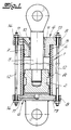
- the actuators shown in the figures are actuators for the high pressure hydraulics. They have at least one pressure cylinder 1 in which a metallic actuating piston 2 with a piston rod 3 is guided.
- FIGS. 1 and 2 From a comparative view of FIGS. 1 and 2 it can be seen that as the pressure cylinder 1, a composite unit made of a metallic liner in the form of a circular cylindrical inner tube 4 and one placed thereon fiber-reinforced plastic tube 5 is executed.
- the plastic tube forms the outer tube.
- the pressure cylinder 1 has metallic end components 6 which are fitted into the pressure cylinder 1 with a cylindrical fitting piece and are connected to it in a sealed manner.
- the end components 6 project with collar formations 8 above the pressure cylinder.
- the arrangement is such that at least one end component 6 has a bore 9 in which the piston rod 3 is guided.
- Usual seals 10 are provided.
- the high-pressure medium is supplied and removed via channels 11 in these end components 6.
- the two end components 6 are connected by tie rods 12 which are held in the collar 8. You are e.g. B. passed through corresponding holes 13.
- the pressure cylinder 1 is stabilized against deformations caused by high pressure medium.
- the pressure cylinder 1 may be under the pressure of a high pressure medium. It can be seen that the pressure cylinder 1 does not have deformations caused by high pressure medium.
- the inner tube 4 is a drawn tube in the form of a precision tube with a wall thickness of less than 1 mm. It was for reasons of scale in Fig. 1 with a drawn excessively thick wall.
- the actuating piston 2 and / or the end components 6 consist of an alloy from the group of steel alloys, aluminum alloys, magnesium alloys, aluminum / magnesium alloys.
- the end components 6 may be positively connected to the inner tube 4, as is indicated in FIG. 1.
- the composite also acts as a seal.
- the collar designs 8 are designed as a circumferential collar, which has a flange-like character in the exemplary embodiment.
- the tie rods 12 are bolts which have nuts 14, via which the tensile force can be adjusted.
- the construction of the plastic tube 5 can only be hinted at. It is designed in detail as it corresponds to claims 9 to 14.
- an actuator constructed according to the teaching of the invention can also have an actuating piston 2 with two piston rods 3 or two actuating pistons 2.
Abstract
Description
Die Erfindung bezieht sich auf einen Stelltrieb der Hochdruckhydraulik, der zumindest einen Druckzylinder aufweist, in dem zumindest ein metallischer Stellkolben mit Kolbenstange geführt ist. Bei einem solchen Stelltrieb ist der Druckzylinder im allgemeinen mit Abschlußbauteilen versehen, die in den Druckzylinder hineingeschoben, über Zugstangen gehalten und gegen den Druckzylinder abgedichtet sind. Im einfachsten Falle ist eines der Abschlußbauteile ein geschlossenes Bauteil und weist das andere eine Bohrung auf, in der die Kolbenstange abgedichtet geführt ist. Der Kolben kann auch beidseitig eine Kolbenstange aufweisen, die in beiden Abschlußbauteilen geführt sind. Im übrigen können in dem Druckzylinder auch mehrere Kolben vorgesehen sein. Es kann sich bei dem Stelltrieb z. B. um einen einfach oder doppelt wirkenden Stelltrieb handeln. Der Kolben eines solchen Stelltriebs besitzt im allgemeinen angeformte metallische Kolbenringe oder polymere Gleitbänder, die die Führung bewirken. Zwischen den Kolbenringen kann eine Weichdichtung angeordnet sein. Hochdruck bezeichnet im Rahmen der Erfindung einen hydrostatischen Druck von über 100 bar, z. B. von 400 bis 500 bar.The invention relates to an actuator of the high-pressure hydraulic system, which has at least one pressure cylinder in which at least one metallic actuating piston with a piston rod is guided. In such an actuator, the pressure cylinder is generally provided with end components which are pushed into the pressure cylinder, held by tie rods and sealed against the pressure cylinder. In the simplest case, one of the end components is a closed component and the other has a bore in which the piston rod is guided in a sealed manner. The piston can also have a piston rod on both sides, which are guided in both end components. In addition, several pistons can also be provided in the pressure cylinder. It can be in the actuator z. B. act as a single or double acting actuator. The piston of such an actuator generally has molded-on metallic piston rings or polymeric sliding bands which effect the guidance. A soft seal can be arranged between the piston rings. In the context of the invention, high pressure denotes a hydrostatic pressure of over 100 bar, for. B. from 400 to 500 bar.
Bei dem aus der Praxis bekannten Stelltrieb, von dem die Erfindung ausgeht, ist der Druckzylinder ein Bauteil aus Stahl, welches eine dem Druck des Hochdruckmittels entsprechende Wanddicke aufweist. Das macht den Stellzylinder zu einem gewichtsmäßig schweren Aggregat.In the actuator known from practice, from which the invention is based, the pressure cylinder is a component made of steel, which has a wall thickness corresponding to the pressure of the high-pressure medium. This makes the actuator a heavy weight unit.
Der Erfindung liegt das technische Problem zugrunde, einen Stellzylinder des eingangs beschriebenen Aufbaus sowie der eingangs beschriebenen Zweckbestimmung zu schaffen, der bei gleicher Leistung und gleichem Druck der Hochdruckhydraulik wesentlich leichter ist und daher insbesondere in Flugzeugen, in Schiffen und anderen Fahrzeugen eingesetzt werden kann, ohne daß eine störende Gewichtserhöhung in Kauf genommen werden müßte.The invention is based on the technical problem of creating an actuating cylinder of the design described at the outset and of the purpose described at the outset, which is much lighter with the same power and the same pressure as the high-pressure hydraulics and can therefore be used in particular in aircraft, in ships and other vehicles without that a disturbing increase in weight would have to be accepted.
Zur Lösung dieses technischen Problems ist Gegenstand der Erfindung die Verwendung eines Verbundaggregates aus einem metallischer Liner in Form eines kreiszylinderischen Innenrohres und einem darauf aufgesetzten, faserverstärkten Kunststoffrohr
als Druckzylinder eines Stelltriebes der Hochdruckhydraulik, der zumindest einen solchen Druckzylinder aufweist, in den ein metallischer Stellkolben mit Kolbenstange in dem Innenrohr geführt arbeitet,
mit der Maßgabe, daß der Druckzylinder metallische Abschlußbauteile aufweist, die mit einem zylindrischen Paßstück in den metallischen Innenliner des Druckzylinders eingepaßt und mit diesem abgedichtet verbunden sind sowie mit Bundausbildungen über den Druckzylinder vorstehen, wobei zumindest ein Abschlußbauteil eine Bohrung aufweist und darin die Kolbenstange geführt ist,
mit der Maßgabe, daß die Zuführung sowie die Abführung des Hochdruckmittels über Kanäle in den Abschlußbauteilen erfolgt und
mit der Maßgabe, daß die beiden Abschlußbauteile durch Zugstangen verbunden sind, die in den Bundausbildungen gehalten sind. Durch den Anschluß des Druckzylinders an die Abschlußbauteile und die Einstellung der Zugkraft der Zugstangen kann der Druckzylinder gegen hochdruckmittelbedingte Verformungen stabilisiert sein. Der Ausdruck Liner bedeutet, daß das Innenrohr sehr dünnwandig ausgeführt ist.To solve this technical problem, the subject of the invention is the use of a composite unit consisting of a metallic liner in the form of a circular cylindrical inner tube and a fiber-reinforced plastic tube placed thereon
as a pressure cylinder of an actuator of the high-pressure hydraulics, which has at least one such pressure cylinder, into which a metallic actuating piston with a piston rod works in the inner tube,
with the proviso that the pressure cylinder has metallic end components which are fitted with a cylindrical fitting into the metallic inner liner of the pressure cylinder and are connected to it in a sealed manner, and project with collar formations above the pressure cylinder, at least one end component having a bore and the piston rod being guided therein ,
with the proviso that the supply and discharge of the high pressure medium takes place via channels in the end components and
with the proviso that the two end components are connected by tie rods, which are held in the collar training. By connecting the pressure cylinder to the end components and adjusting the tensile force of the pull rods, the pressure cylinder can be stabilized against deformations caused by high pressure medium. The expression liner means that the inner tube has a very thin wall.
Bevorzugte Ausführungsformen der erfindungsgemäßen Verwendung sind Gegenstand der Patentansprüche 2 bis 4.Preferred embodiments of the use according to the invention are the subject of
Stelltriebe, die einen Druckzylinder aus einem metallischen Liner und eine Ummantelung aus faserbewährtem Kunststoff aufweisen, sind bekannt (WO 93/23675). Der metallische Liner und die Ummantelung sind hier nicht als kreiszylindrische Rohre ausgeführt. Die Fertigung ist daher aufwendig. Im übrigen sind auch Stelltriebe bekannt, die einen Druckzylinder aus Innenrohr und Außenrohr aufweisen (WO 91/11319), die beide aus faserbewährtem Kunststoff bestehen. Diese Stelltriebe sind für die Hochdruckhydraulik wenig geeignet.Actuators that have a pressure cylinder made of a metallic liner and a casing made of fiber-proven plastic are known (WO 93/23675). The metallic liner and the casing are not designed as circular cylindrical tubes. The manufacture is therefore complex. Actuators are also known which have a pressure cylinder made of an inner tube and an outer tube (WO 91/11319), both of which consist of fiber-proven plastic. These actuators are not very suitable for high pressure hydraulics.
Die Erfindung geht von der Erkenntnis aus, daß bei einem Stelltrieb für die Hochdruckhydraulik des beschriebenen Aufbaus der Druckzylinder aus einem dünnwandigen Innenrohr und einem faserverstärkten Kunststoffrohr bestehen können, wenn die im Patentanspruch 1 beschriebenen Maßgaben verwirklicht sind und wenn durch den Anschluß des Druckzylinders an die Abschlußbauteile und die Einstellung der Zugstangen der Druckzylinder gegen hochdruckmittelbedingte Verformungen stabilisiert ist. Bei einem erfindungsgemäßen Stelltrieb würde das Hochdruckmittel in dem Außenrohr, welches mit den Abschlußbauteilen verbunden ist, ohne weiteres in Umfangsrichtung verlaufende Zugkräfte produzieren, wobei das Hochdruckmittel den Durchmesser des Außenrohres vergrößert. Daraus würde eine Beeinträchtigung der Dichtigkeit zwischen dem Kolben und dem Innenrohr resultieren. Überraschenderweise läßt sich diese störende Verformung verhindern, wenn in der beschriebenen Weise ein Faserverbund-Außenrohr mit hohem Elastizitätsmodul in Umfangsrichtung eingesetzt wird. Der Außenmantel steht über die Zuganker unter geringer Vorspannung, wenn das Hochdruckmittel nicht ansteht. Die Vorspannung kann auch ohne einen kraftschlüssigen Verbund zwischen den Abschlußbauteilen und dem Innenmantel so eingerichtet werden, daß unter dem Druck des Hochdruckmittels störende Verformungen des Druckzylinders nicht auftreten. Im Rahmen der Erfindung bezeichnet Verbundaggregat aus einem metallischen Liner in Form eines kreiszylindrischen Innenrohres und einem darauf aufgesetzten kunststoffaserverstärkten Kunststoffrohr ein Aggregat aus diesen beiden Bauteilen, gleichgültig, ob das faserverstärkte Kunststoffrohr über eine Schrumpfverbindung oder über eine Klebverbindung mit dem metallischen Innenrohr verbunden ist. Im einfachsten Fall kann der Verbund auch dadurch gegeben sein, daß das Außenrohr auf das Innenrohr direkt aufgewickelt ist, wobei die unterschiedlichen Wärmedehnungen der beiden Werkstoffe, Metall einerseits und faserverstärkten Kunststoff andererseits, -gezielt ausgenutzt werden können. Im Ergebnis führt die Lehre der Erfindung zu einem Stelltrieb sehr leichter Bauweise, der nichtsdestoweniger extrem hohe Drücke des Hochdruckmittels aufzunehmen in der Lage ist und entsprechende Stellkräfte produzieren kann. Die nach der Lehre der Erfindung aufgebauten Stelltriebe zeichnen sich darüber hinaus durch lange Standzeit aus. Sie sind nichtsdestoweniger als Massenartikel einfach zu fertigen. - Im Rahmen der erfindungsgemäßen Verwendung nimmt der Druckzylinder druckmittelbedingte axiale Kräfte nicht auf. Diese werden ausschließlich durch die Zugstange aufgenommen, die eine Verformung in Umfangs- bzw. Radialrichtung nicht behindern. Die über die Zugstangen bewirkte Vorspannung ist gering. Beulende Verformungen des Druckzylinders werden vermieden. Einer störenden Durchmesservergrößerung in Folge des Innendruckes wirkt das hochsteife Faserverbundrohr entgegen.The invention is based on the knowledge that in an actuator for the high-pressure hydraulics of the structure described, the pressure cylinder consists of a thin-walled inner tube and a fiber-reinforced plastic tube can exist if the requirements described in
Im Rahmen der Erfindung können die Bundausbildungen als umlaufender Bund ausgeführt und an die Paßstücke angeformt sein. Es besteht aber auch die Möglichkeit, die Bundausnehmungen als Bundabschnitte auszuführen und an die Paßstücke anzuformen. Je nach der Gestaltung der Bundausbildungen könnte man auch von Flanschen sprechen. Nach bevorzugter Ausführungsform der Erfindung sind die Zugstangen als Schraubenbolzen ausgeführt und weisen diese Muttern auf, über die die Zugkraft einstellbar ist. Das faserverstärkte Kunststoffrohr ist im Detail zweckmäßigerweise so ausgeführt, wie es sich aus den Patentansprüchen 9 bis 14 ergibt.In the context of the invention, the collar designs can be designed as a circumferential collar and molded onto the adapters. But there is also the possibility to design the collar recesses as collar sections and to form them onto the adapters. Depending on the design of the federal government training, one could also speak of flanges. According to a preferred embodiment of the invention Drawbars designed as bolts and have these nuts, via which the tensile force can be adjusted. The fiber-reinforced plastic tube is expediently designed in detail as it results from the
Im folgenden wird die Erfindung anhand einer lediglich ein Ausführungsbeispiel darstellenden Zeichnung ausführlicher erläutert. Es zeigen in schematischer Darstellung
- Fig. 1
- einen Längsschnitt durch einen Stelltrieb, der nach der Lehre der Erfindung aufgebaut ist,
- Fig. 2
- in gegenüber der Fig. 1 sehr starker Vergrößerung den Ausschnitt A aus dem Gegenstand der Fig. 1 und
- Fig. 3
- mit den Teilfiguren a und b in weiterer Schematisierung andere Ausführungsformen von nach der Lehre der Erfindung aufgebauten Stelltrieben.
- Fig. 1
- 2 shows a longitudinal section through an actuator which is constructed according to the teaching of the invention,
- Fig. 2
- in a very large enlargement compared to FIG. 1, section A from the subject of FIGS. 1 and
- Fig. 3
- with the sub-figures a and b in a further schematic other embodiments of actuators constructed according to the teaching of the invention.
Die in den Figuren dargestellten Stelltriebe sind Stelltriebe für die Hochdruckhydraulik. Sie besitzen zumindest einen Druckzylinder 1, in dem ein metallischer Stellkolben 2 mit Kolbenstange 3 geführt ist.The actuators shown in the figures are actuators for the high pressure hydraulics. They have at least one
Aus einer vergleichenden Betrachtung der Fig. 1 und 2 entnimmt man, daß als Druckzylinder 1 ein Verbundaggregat aus einem metallischen Liner in Form eines kreiszylindrischen Innenrohres 4 und einem darauf aufgesetzten faserverstärkten Kunststoffrohr 5 ausgeführt ist. Das Kunststoffrohr bildet das Außenrohr.From a comparative view of FIGS. 1 and 2 it can be seen that as the
Man erkennt in den Fig. 1 und 2, daß der Druckzylinder 1 metallische Abschlußbauteile 6 aufweist, die mit einem zylindrischen Paßstück 7 in den Druckzylinder 1 eingepaßt und mit diesem abgedichtet verbunden sind. Die Abschlußbauteile 6 stehen mit Bundausbildungen 8 über den Druckzylinder vor. Die Anordnung ist so getroffen, daß zumindest ein Abschlußbauteil 6 eine Bohrung 9 aufweist, in der die Kolbenstange 3 geführt ist. Übliche Dichtungen 10 sind vorgesehen. Die Zuführung sowie die Abführung des Hochdruckmittels erfolgt über Kanäle 11 in diesen Abschlußbauteilen 6.It can be seen in FIGS. 1 and 2 that the
Die beiden Abschlußbauteile 6 sind durch Zugstangen 12 verbunden, die in den Bundausbildungen 8 gehalten sind. Sie sind z. B. durch entsprechende Bohrungen 13 hindurchgeführt. Durch den Anschluß des Druckzylinders 1 an die Abschlußbauteile 6 und durch die Einstellung der Zugkraft der Zugstangen 12 ist der Druckzylinder 1 gegen hochdruckmittelbedingte Verformungen stabilisiert. In der Fig. 1 mag der Druckzylinder 1 unter dem Druck eines Hochdruckmittels stehen. Man erkennt, daß der Druckzylinder 1 hochdruckmittelbedingte Verformungen nicht aufweist. Das Innenrohr 4 ist im Ausführungsbeispiel und nach bevorzugter Ausführungsform der Erfindung ein gezogenes Rohr in Form eines Präzisionsrohres mit einer Wanddicke von unter 1 mm. Es wurde aus Maßstabsgründen in Fig. 1 mit einer übertrieben dicken Wanddicke gezeichnet.The two
Der Stellkolben 2 und/oder die Abschlußbauteile 6 bestehen aus einer Legierung der Gruppe Stahllegierungen, Aluminiumlegierungen, Magnesiumlegierungen, Aluminium/Magnesiumlegierungen. Die Abschlußbauteile 6 mögen mit dem Innenrohr 4 formschlüssig verbunden sein, wie es in der Fig. 1 angedeutet ist. Der Verbund wirkt gleichzeitig abdichtend.The
Im Ausführungsbeispiel und nach bevorzugter Ausführungsform der Erfindung sind die Bundausbildungen 8 als umlaufender Bund ausgeführt, der im Ausführungsbeispiel flanschartigen Charakter hat. Die Zugstangen 12 sind Schraubenbolzen, die Muttern 14 aufweisen, über die die Zugkraft einstellbar ist. Aus Maßstabsgründen kann der Aufbau des Kunststoffrohres 5 nur angedeutet sein. Er ist im einzelnen so gestaltet, wie es den Patentansprüchen 9 bis 14 entspricht. In der Fig. 3 wurde angedeutet, daß ein nach der Lehre der Erfindung aufgebauter Stelltrieb auch einen Stellkolben 2 mit zwei Kolbenstangen 3 oder zwei Stellkolben 2 aufweisen kann.In the exemplary embodiment and according to a preferred embodiment of the invention, the collar designs 8 are designed as a circumferential collar, which has a flange-like character in the exemplary embodiment. The
Claims (14)
als Druckzylinder (1) eines Stelltriebes der Hochdruckhydraulik, der zumindest einen solchen Druckzylinder (1) aufweist, in den ein metallischer Stellkolben (2) mit Kolbenstange (3) in dem Innenrohr (4) geführt arbeitet,
mit der Maßgabe, daß der Druckzylinder (1) metallische Abschlußbauteile (6) aufweist, die mit einem zylindrischen Paßstück (7) in den Druckzylinder (1) eingepaßt und mit diesem abgedichtet verbunden sind sowie mit Bundausbildungen (8) über den Druckzylinder (1) vorstehen, wobei zumindest ein Abschlußbauteil (6) eine Bohrung (9) aufweist und darin die Kolbenstange (3) geführt ist,
mit der Maßgabe, daß die Zuführung sowie die Abführung des Hochdruckmittels über Kanäle (11) in den Abschlußbauteilen (6) erfolgt, und
mit der Maßgabe, daß die beiden Abschlußbauteile (6) durch Zugstangen (12) verbunden sind, die in den Bundausbildungen (8) gehalten sind, wobei durch den Anschluß des Druckzylinders (1) an die Abschlußbauteile (6) und die Einstellung der Zugkraft der Zugstangen (12) der Druckzylinder (1) gegen hochdruckmittelbedingte Verformungen stabilisiert ist.Use of a composite unit consisting of a metallic liner in the form of a circular cylindrical inner tube (4) and a fiber-reinforced plastic tube (5) placed thereon
as a pressure cylinder (1) of an actuator of the high-pressure hydraulics, which has at least one such pressure cylinder (1) into which a metallic actuating piston (2) with a piston rod (3) works in the inner tube (4),
with the proviso that the pressure cylinder (1) has metallic end components (6) which are fitted with a cylindrical fitting (7) into the pressure cylinder (1) and are connected to it in a sealed manner, and with collar formations (8) via the pressure cylinder (1) protrude, at least one end component (6) having a bore (9) and the piston rod (3) being guided therein,
with the proviso that the supply and the discharge of the high pressure medium via channels (11) in the end components (6), and
with the proviso that the two end components (6) are connected by tie rods (12) which are held in the collar formations (8), the connection of the pressure cylinder (1) to the end components (6) and the adjustment the tensile force of the tie rods (12) of the pressure cylinder (1) is stabilized against deformation caused by high pressure medium.
Applications Claiming Priority (2)
| Application Number | Priority Date | Filing Date | Title |
|---|---|---|---|
| DE4430502 | 1994-08-27 | ||
| DE19944430502 DE4430502C2 (en) | 1994-08-27 | 1994-08-27 | Use of a composite unit consisting of a liner and a fiber-reinforced plastic tube as the pressure cylinder of an actuator of the high-pressure hydraulics |
Publications (3)
| Publication Number | Publication Date |
|---|---|
| EP0701065A2 true EP0701065A2 (en) | 1996-03-13 |
| EP0701065A3 EP0701065A3 (en) | 1996-12-27 |
| EP0701065B1 EP0701065B1 (en) | 2000-03-01 |
Family
ID=6526745
Family Applications (1)
| Application Number | Title | Priority Date | Filing Date |
|---|---|---|---|
| EP19950112898 Expired - Lifetime EP0701065B1 (en) | 1994-08-27 | 1995-08-17 | Pressure actuator for high pressure hydraulics |
Country Status (4)
| Country | Link |
|---|---|
| EP (1) | EP0701065B1 (en) |
| DE (1) | DE4430502C2 (en) |
| DK (1) | DK0701065T3 (en) |
| ES (1) | ES2145858T3 (en) |
Cited By (8)
| Publication number | Priority date | Publication date | Assignee | Title |
|---|---|---|---|---|
| DE19649133C1 (en) * | 1996-11-27 | 1998-03-05 | Dornier Gmbh | Hydraulic cylinder |
| EP0841490A2 (en) | 1996-11-05 | 1998-05-13 | Deutsches Zentrum für Luft- und Raumfahrt e.V. | Device for force introduction |
| WO1998022715A3 (en) * | 1996-11-16 | 1998-09-03 | Lingk & Sturzebecher Leichtbau | Piston rod for an adjusting piston of an actuator |
| WO2006055997A1 (en) | 2004-11-25 | 2006-06-01 | HÖLZL, Margit | Cylinder for high-pressure hydraulics |
| US7984731B2 (en) | 2007-11-13 | 2011-07-26 | Parker-Hannifin Corporation | Lightweight high pressure repairable piston tie rod composite accumulator |
| US8262825B2 (en) | 2007-09-11 | 2012-09-11 | Parker Hannifin Gmbh | End-fittings for composite tubes, method for joining fittings to the ends of composite tubes and composite tubes incorporating end-fitting |
| US8695643B2 (en) | 2007-11-08 | 2014-04-15 | Parker-Hannifin Corporation | Lightweight high pressure repairable piston composite accumulator with slip flange |
| DE102009014813B4 (en) * | 2009-03-25 | 2014-10-23 | Festo Ag & Co. Kg | linear actuator |
Families Citing this family (11)
| Publication number | Priority date | Publication date | Assignee | Title |
|---|---|---|---|---|
| DE19732934A1 (en) * | 1997-07-31 | 1999-02-04 | Mannesmann Rexroth Ag | Hydraulic cylinder in tie rod design, especially for small presses |
| DE19811657A1 (en) * | 1998-03-18 | 1999-09-23 | Schaeffler Waelzlager Ohg | Vehicle hydraulic clutch disengaging system |
| EP0987446A1 (en) * | 1998-09-15 | 2000-03-22 | Lingk & Sturzebecher Leichtbau GmbH | Hydraulic cylinder |
| DE19925600A1 (en) * | 1999-06-04 | 2000-12-14 | Sbs Sondermaschinen Gmbh | Light construction hydraulic cylinder has tie rod mounted in outer cylinder tube that bears peripheral forces of hydraulic internal pressure, either outside or inside working chamber |
| DE102004008523B4 (en) * | 2004-02-20 | 2007-02-01 | Liebherr-Aerospace Lindenberg Gmbh | Method for producing a printing cylinder and piston rod for actuators or shock absorbers and method for their production |
| DE102006047413B4 (en) * | 2005-10-06 | 2014-01-16 | Technische Universität Dresden | Cylinder made of fiber composite material with metallic flange components and method of manufacture |
| DE102009029299B4 (en) | 2009-09-09 | 2015-12-31 | Leichtbau-Zentrum Sachsen Gmbh | vibration |
| AT512703B1 (en) * | 2012-04-12 | 2014-06-15 | Neuson Hydrotec Gmbh | Piston-cylinder unit |
| DE102015211545B3 (en) * | 2015-06-23 | 2016-11-10 | Innotec Lightweight Engineering & Polymer Technology Gmbh | Cylinder tube for a hydraulic or pneumatic cylinder |
| DE102017000857A1 (en) * | 2017-01-31 | 2018-08-02 | Liebherr-Components Kirchdorf GmbH | A cylinder piston device |
| EP3546787B1 (en) * | 2018-03-27 | 2021-02-24 | Aida Engineering, Ltd. | Gas cushion device |
Citations (2)
| Publication number | Priority date | Publication date | Assignee | Title |
|---|---|---|---|---|
| WO1991011319A1 (en) | 1990-01-25 | 1991-08-08 | Hitachi Construction Machinery Co., Ltd. | Pressure vessel made of composite material |
| WO1993023675A1 (en) | 1992-05-13 | 1993-11-25 | Hr Textron Inc. | Composite cylinder for use in aircraft hydraulic actuator |
Family Cites Families (7)
| Publication number | Priority date | Publication date | Assignee | Title |
|---|---|---|---|---|
| US3286737A (en) * | 1963-08-01 | 1966-11-22 | Dowsmith Inc | Wear-resistant article and method of making the same |
| DE6916307U (en) * | 1969-04-23 | 1969-09-04 | Kloeckner Werke Ag | PRESSURE CYLINDER |
| FR2554876B1 (en) * | 1983-11-10 | 1988-02-26 | Peugeot Aciers Et Outillage | COMPOSITE MATERIAL BASED CYLINDER |
| IT1185613B (en) * | 1985-05-30 | 1987-11-12 | Magnaghi Cleodinamica Spa | GAS-OIL PRESSURE ACCUMULATOR WITH COMPOSITE MATERIAL STRUCTURE FOR AIRCRAFT HYDRAULIC CIRCUITS |
| US4885981A (en) * | 1988-04-08 | 1989-12-12 | General Signal Corporation | Spring return cylinder actuator |
| DE9207582U1 (en) * | 1992-06-04 | 1992-08-20 | Festo Kg, 7300 Esslingen, De | |
| JPH0829265B2 (en) * | 1992-12-09 | 1996-03-27 | 崇 川合 | Granule sorter |
-
1994
- 1994-08-27 DE DE19944430502 patent/DE4430502C2/en not_active Expired - Lifetime
-
1995
- 1995-08-17 ES ES95112898T patent/ES2145858T3/en not_active Expired - Lifetime
- 1995-08-17 EP EP19950112898 patent/EP0701065B1/en not_active Expired - Lifetime
- 1995-08-17 DK DK95112898T patent/DK0701065T3/en active
Patent Citations (2)
| Publication number | Priority date | Publication date | Assignee | Title |
|---|---|---|---|---|
| WO1991011319A1 (en) | 1990-01-25 | 1991-08-08 | Hitachi Construction Machinery Co., Ltd. | Pressure vessel made of composite material |
| WO1993023675A1 (en) | 1992-05-13 | 1993-11-25 | Hr Textron Inc. | Composite cylinder for use in aircraft hydraulic actuator |
Cited By (9)
| Publication number | Priority date | Publication date | Assignee | Title |
|---|---|---|---|---|
| EP0841490A2 (en) | 1996-11-05 | 1998-05-13 | Deutsches Zentrum für Luft- und Raumfahrt e.V. | Device for force introduction |
| DE19645467A1 (en) * | 1996-11-05 | 1998-05-14 | Deutsch Zentr Luft & Raumfahrt | Force application device |
| WO1998022715A3 (en) * | 1996-11-16 | 1998-09-03 | Lingk & Sturzebecher Leichtbau | Piston rod for an adjusting piston of an actuator |
| DE19649133C1 (en) * | 1996-11-27 | 1998-03-05 | Dornier Gmbh | Hydraulic cylinder |
| WO2006055997A1 (en) | 2004-11-25 | 2006-06-01 | HÖLZL, Margit | Cylinder for high-pressure hydraulics |
| US8262825B2 (en) | 2007-09-11 | 2012-09-11 | Parker Hannifin Gmbh | End-fittings for composite tubes, method for joining fittings to the ends of composite tubes and composite tubes incorporating end-fitting |
| US8695643B2 (en) | 2007-11-08 | 2014-04-15 | Parker-Hannifin Corporation | Lightweight high pressure repairable piston composite accumulator with slip flange |
| US7984731B2 (en) | 2007-11-13 | 2011-07-26 | Parker-Hannifin Corporation | Lightweight high pressure repairable piston tie rod composite accumulator |
| DE102009014813B4 (en) * | 2009-03-25 | 2014-10-23 | Festo Ag & Co. Kg | linear actuator |
Also Published As
| Publication number | Publication date |
|---|---|
| DK0701065T3 (en) | 2000-07-31 |
| EP0701065B1 (en) | 2000-03-01 |
| EP0701065A3 (en) | 1996-12-27 |
| ES2145858T3 (en) | 2000-07-16 |
| DE4430502C2 (en) | 1999-08-19 |
| DE4430502A1 (en) | 1996-02-29 |
Similar Documents
| Publication | Publication Date | Title |
|---|---|---|
| EP0701065A2 (en) | Pressure actuator for high pressure hydraulics | |
| EP1819928B1 (en) | Cylinder for high-pressure hydraulics | |
| EP0326844B1 (en) | Shut-off or control valve | |
| DE19830136C2 (en) | Combined service brake and spring brake cylinder | |
| DE8324715U1 (en) | TUBULAR HOLLOW BODY, ESPECIALLY FOR TRANSMITTING PRESSURE, TOW, BENDING AND TWISTING FORCES IN VEHICLES | |
| DE19647506C2 (en) | Piston rod for an actuating piston of an actuator | |
| DE2926493C2 (en) | Strut for longitudinal pull and pressure | |
| EP1714866A1 (en) | Monocoque structure | |
| DE19520680C2 (en) | Hydraulic unit | |
| DE3414821C2 (en) | Sealing arrangement | |
| DE202004004375U1 (en) | Sleeve for printing machines | |
| CH652176A5 (en) | Elongate force-transmission element and process for producing it | |
| DE19935516B4 (en) | Bottle for pressurized gases | |
| CH413508A (en) | Split connecting rod end | |
| DE6916307U (en) | PRESSURE CYLINDER | |
| DE102004021144B4 (en) | Connection for the transmission of tensile forces in bars or inner pressure-loaded tubes | |
| DE102020134633A1 (en) | Pressure tank for gas-powered vehicle | |
| DE3323407C2 (en) | Cylinders for hydraulic systems | |
| EP0589863A1 (en) | Hydraulic cylinder | |
| EP1258339B1 (en) | Fibre reinforced plastic article | |
| DE3134771A1 (en) | Cylinder liner for internal combustion piston engines | |
| WO1996023684A1 (en) | Hydraulic unit | |
| DE2406566A1 (en) | Hydraulic cylinder for rack and pinion steering - features cylinder tube with end closure and connecting components for hydraulic supply | |
| DE102015014611A1 (en) | Compressed gas tank with a shell | |
| DE3249581A1 (en) | Cast engine connecting rod |
Legal Events
| Date | Code | Title | Description |
|---|---|---|---|
| PUAI | Public reference made under article 153(3) epc to a published international application that has entered the european phase |
Free format text: ORIGINAL CODE: 0009012 |
|
| AK | Designated contracting states |
Kind code of ref document: A2 Designated state(s): DK ES FR GB IT NL SE |
|
| 17P | Request for examination filed |
Effective date: 19960727 |
|
| PUAL | Search report despatched |
Free format text: ORIGINAL CODE: 0009013 |
|
| AK | Designated contracting states |
Kind code of ref document: A3 Designated state(s): DK ES FR GB IT NL SE |
|
| 17Q | First examination report despatched |
Effective date: 19980717 |
|
| GRAG | Despatch of communication of intention to grant |
Free format text: ORIGINAL CODE: EPIDOS AGRA |
|
| GRAG | Despatch of communication of intention to grant |
Free format text: ORIGINAL CODE: EPIDOS AGRA |
|
| GRAH | Despatch of communication of intention to grant a patent |
Free format text: ORIGINAL CODE: EPIDOS IGRA |
|
| GRAH | Despatch of communication of intention to grant a patent |
Free format text: ORIGINAL CODE: EPIDOS IGRA |
|
| GRAA | (expected) grant |
Free format text: ORIGINAL CODE: 0009210 |
|
| AK | Designated contracting states |
Kind code of ref document: B1 Designated state(s): DK ES FR GB IT NL SE |
|
| GBT | Gb: translation of ep patent filed (gb section 77(6)(a)/1977) |
Effective date: 20000407 |
|
| ITF | It: translation for a ep patent filed |
Owner name: ING. A. GIAMBROCONO & C. S.R.L. |
|
| ET | Fr: translation filed | ||
| REG | Reference to a national code |
Ref country code: ES Ref legal event code: FG2A Ref document number: 2145858 Country of ref document: ES Kind code of ref document: T3 |
|
| REG | Reference to a national code |
Ref country code: DK Ref legal event code: T3 |
|
| PLBE | No opposition filed within time limit |
Free format text: ORIGINAL CODE: 0009261 |
|
| STAA | Information on the status of an ep patent application or granted ep patent |
Free format text: STATUS: NO OPPOSITION FILED WITHIN TIME LIMIT |
|
| 26N | No opposition filed | ||
| REG | Reference to a national code |
Ref country code: GB Ref legal event code: IF02 |
|
| REG | Reference to a national code |
Ref country code: GB Ref legal event code: 732E Free format text: REGISTERED BETWEEN 20100408 AND 20100414 |
|
| REG | Reference to a national code |
Ref country code: ES Ref legal event code: PC2A |
|
| REG | Reference to a national code |
Ref country code: FR Ref legal event code: TQ |
|
| REG | Reference to a national code |
Ref country code: NL Ref legal event code: SD Effective date: 20100723 |
|
| PGFP | Annual fee paid to national office [announced via postgrant information from national office to epo] |
Ref country code: ES Payment date: 20130829 Year of fee payment: 19 |
|
| PGFP | Annual fee paid to national office [announced via postgrant information from national office to epo] |
Ref country code: NL Payment date: 20140820 Year of fee payment: 20 Ref country code: DK Payment date: 20140820 Year of fee payment: 20 |
|
| PGFP | Annual fee paid to national office [announced via postgrant information from national office to epo] |
Ref country code: FR Payment date: 20140821 Year of fee payment: 20 Ref country code: SE Payment date: 20140820 Year of fee payment: 20 Ref country code: GB Payment date: 20140820 Year of fee payment: 20 |
|
| PGFP | Annual fee paid to national office [announced via postgrant information from national office to epo] |
Ref country code: IT Payment date: 20140828 Year of fee payment: 20 |
|
| REG | Reference to a national code |
Ref country code: DK Ref legal event code: EUP Effective date: 20150817 |
|
| REG | Reference to a national code |
Ref country code: NL Ref legal event code: V4 Effective date: 20150817 |
|
| REG | Reference to a national code |
Ref country code: GB Ref legal event code: PE20 Expiry date: 20150816 |
|
| REG | Reference to a national code |
Ref country code: ES Ref legal event code: FD2A Effective date: 20150925 |
|
| REG | Reference to a national code |
Ref country code: SE Ref legal event code: EUG |
|
| PG25 | Lapsed in a contracting state [announced via postgrant information from national office to epo] |
Ref country code: GB Free format text: LAPSE BECAUSE OF EXPIRATION OF PROTECTION Effective date: 20150816 Ref country code: ES Free format text: LAPSE BECAUSE OF NON-PAYMENT OF DUE FEES Effective date: 20140818 |