EP0700877B1 - Schneidevorrichtung mit einem Schneidewerkzeug das, in Abhängigkeit der totalen Schnittlänge, mit variablen Druck auf die nacheinanderfolgenden Werkstücke gedrückt wird - Google Patents
Schneidevorrichtung mit einem Schneidewerkzeug das, in Abhängigkeit der totalen Schnittlänge, mit variablen Druck auf die nacheinanderfolgenden Werkstücke gedrückt wird Download PDFInfo
- Publication number
- EP0700877B1 EP0700877B1 EP95114104A EP95114104A EP0700877B1 EP 0700877 B1 EP0700877 B1 EP 0700877B1 EP 95114104 A EP95114104 A EP 95114104A EP 95114104 A EP95114104 A EP 95114104A EP 0700877 B1 EP0700877 B1 EP 0700877B1
- Authority
- EP
- European Patent Office
- Prior art keywords
- cutting
- pressure
- workpieces
- air
- series
- Prior art date
- Legal status (The legal status is an assumption and is not a legal conclusion. Google has not performed a legal analysis and makes no representation as to the accuracy of the status listed.)
- Expired - Lifetime
Links
- 238000005520 cutting process Methods 0.000 title claims description 89
- 230000001276 controlling effect Effects 0.000 claims description 36
- 230000001105 regulatory effect Effects 0.000 claims description 5
- 238000003825 pressing Methods 0.000 claims description 4
- 238000002203 pretreatment Methods 0.000 claims description 4
- 239000000919 ceramic Substances 0.000 description 28
- 230000007246 mechanism Effects 0.000 description 10
- 239000003638 chemical reducing agent Substances 0.000 description 8
- 238000010586 diagram Methods 0.000 description 4
- 230000003584 silencer Effects 0.000 description 4
- 238000013500 data storage Methods 0.000 description 3
- 230000003247 decreasing effect Effects 0.000 description 3
- 230000008878 coupling Effects 0.000 description 2
- 238000010168 coupling process Methods 0.000 description 2
- 238000005859 coupling reaction Methods 0.000 description 2
- 230000006866 deterioration Effects 0.000 description 2
- 239000011521 glass Substances 0.000 description 2
- 238000009434 installation Methods 0.000 description 2
- 238000012544 monitoring process Methods 0.000 description 2
- 238000005299 abrasion Methods 0.000 description 1
- 230000008859 change Effects 0.000 description 1
- 230000001419 dependent effect Effects 0.000 description 1
- 229910003460 diamond Inorganic materials 0.000 description 1
- 239000010432 diamond Substances 0.000 description 1
- 239000000428 dust Substances 0.000 description 1
- 239000000314 lubricant Substances 0.000 description 1
- 239000010687 lubricating oil Substances 0.000 description 1
- 238000000034 method Methods 0.000 description 1
- 238000012986 modification Methods 0.000 description 1
- 230000004048 modification Effects 0.000 description 1
- 239000000843 powder Substances 0.000 description 1
- 230000008569 process Effects 0.000 description 1
- 230000002035 prolonged effect Effects 0.000 description 1
- 230000009467 reduction Effects 0.000 description 1
Images



Classifications
-
- C—CHEMISTRY; METALLURGY
- C03—GLASS; MINERAL OR SLAG WOOL
- C03B—MANUFACTURE, SHAPING, OR SUPPLEMENTARY PROCESSES
- C03B33/00—Severing cooled glass
- C03B33/10—Glass-cutting tools, e.g. scoring tools
-
- B—PERFORMING OPERATIONS; TRANSPORTING
- B28—WORKING CEMENT, CLAY, OR STONE
- B28D—WORKING STONE OR STONE-LIKE MATERIALS
- B28D1/00—Working stone or stone-like materials, e.g. brick, concrete or glass, not provided for elsewhere; Machines, devices, tools therefor
- B28D1/22—Working stone or stone-like materials, e.g. brick, concrete or glass, not provided for elsewhere; Machines, devices, tools therefor by cutting, e.g. incising
- B28D1/225—Working stone or stone-like materials, e.g. brick, concrete or glass, not provided for elsewhere; Machines, devices, tools therefor by cutting, e.g. incising for scoring or breaking, e.g. tiles
-
- B—PERFORMING OPERATIONS; TRANSPORTING
- B28—WORKING CEMENT, CLAY, OR STONE
- B28D—WORKING STONE OR STONE-LIKE MATERIALS
- B28D7/00—Accessories specially adapted for use with machines or devices of the preceding groups
- B28D7/005—Devices for the automatic drive or the program control of the machines
-
- Y—GENERAL TAGGING OF NEW TECHNOLOGICAL DEVELOPMENTS; GENERAL TAGGING OF CROSS-SECTIONAL TECHNOLOGIES SPANNING OVER SEVERAL SECTIONS OF THE IPC; TECHNICAL SUBJECTS COVERED BY FORMER USPC CROSS-REFERENCE ART COLLECTIONS [XRACs] AND DIGESTS
- Y10—TECHNICAL SUBJECTS COVERED BY FORMER USPC
- Y10T—TECHNICAL SUBJECTS COVERED BY FORMER US CLASSIFICATION
- Y10T83/00—Cutting
- Y10T83/02—Other than completely through work thickness
- Y10T83/0333—Scoring
- Y10T83/0348—Active means to control depth of score
-
- Y—GENERAL TAGGING OF NEW TECHNOLOGICAL DEVELOPMENTS; GENERAL TAGGING OF CROSS-SECTIONAL TECHNOLOGIES SPANNING OVER SEVERAL SECTIONS OF THE IPC; TECHNICAL SUBJECTS COVERED BY FORMER USPC CROSS-REFERENCE ART COLLECTIONS [XRACs] AND DIGESTS
- Y10—TECHNICAL SUBJECTS COVERED BY FORMER USPC
- Y10T—TECHNICAL SUBJECTS COVERED BY FORMER US CLASSIFICATION
- Y10T83/00—Cutting
- Y10T83/02—Other than completely through work thickness
- Y10T83/0333—Scoring
- Y10T83/0385—Rotary scoring blade
-
- Y—GENERAL TAGGING OF NEW TECHNOLOGICAL DEVELOPMENTS; GENERAL TAGGING OF CROSS-SECTIONAL TECHNOLOGIES SPANNING OVER SEVERAL SECTIONS OF THE IPC; TECHNICAL SUBJECTS COVERED BY FORMER USPC CROSS-REFERENCE ART COLLECTIONS [XRACs] AND DIGESTS
- Y10—TECHNICAL SUBJECTS COVERED BY FORMER USPC
- Y10T—TECHNICAL SUBJECTS COVERED BY FORMER US CLASSIFICATION
- Y10T83/00—Cutting
- Y10T83/02—Other than completely through work thickness
- Y10T83/0333—Scoring
- Y10T83/0385—Rotary scoring blade
- Y10T83/0393—With means to rotate blade
-
- Y—GENERAL TAGGING OF NEW TECHNOLOGICAL DEVELOPMENTS; GENERAL TAGGING OF CROSS-SECTIONAL TECHNOLOGIES SPANNING OVER SEVERAL SECTIONS OF THE IPC; TECHNICAL SUBJECTS COVERED BY FORMER USPC CROSS-REFERENCE ART COLLECTIONS [XRACs] AND DIGESTS
- Y10—TECHNICAL SUBJECTS COVERED BY FORMER USPC
- Y10T—TECHNICAL SUBJECTS COVERED BY FORMER US CLASSIFICATION
- Y10T83/00—Cutting
- Y10T83/162—With control means responsive to replaceable or selectable information program
- Y10T83/173—Arithmetically determined program
Definitions
- This invention relates to a cutting apparatus and, more particularly, to a cutting apparatus equipped with a cutting tool variably pressed against a brittle workpiece of ceramic or glass depending upon running hours.
- FIG. 1 A typical example of the cutting apparatus for a glass plate and a ceramic plate is called a "scriber", and figure 1 illustrates the scriber available for cutting a ceramic plate.
- the prior art scriber largely comprises a working table structure 1, a wheel cutter 2, a driving system 3 for the wheel cutter 2 and a controlling system 4 for the driving system 3.
- the working table structure 1 includes a rigid base 1a, a movable table 1b movable in Y-direction with respect to the rigid base 1a and a driving mechanism (not shown) for moving the movable table 1b under the control of the controlling system 4.
- a workpiece or a ceramic plate 5 is mounted on the movable table 1b, and is moved together with the movable table 1b in the Y-direction.
- the wheel cutter 2 is supported by a suitable retainer 2a, and the retainer 2a is functionally connected to the driving system 3.
- the driving system 3 includes a slide 3a and a servo-motor (not shown), and moves the retainer 2a and, accordingly, the wheel cutter 2 in X-direction with respect to the rigid base 1a.
- the controlling system 4 includes a pusher 4a provided for the retainer 2a and a pneumatic control sub-system 4b.
- a cylinder 4c, a plunger 4d movable in the cylinder 4c and a return spring 4e form in combination the pusher, and the retainer 2a is connected to the leading end of the plunger 4d.
- the plunger 4d is reciprocally movable and moves telescopically from and into the cylinder 4c.
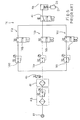
- the pneumatic control sub-system 4b is connected to a high-pressure air source 4f, and includes a combination unit 4g of air filter and pressure regulator, a lubricator 4h and a solenoid-operated three-port valve 4i.
- the three ports are labeled with “P", “A” and “R”, and the solenoid 4j and a return spring 4k change the connection between the three ports "P", "A” and “R”.
- the high-pressure air is supplied to the inlet port "P", and the outlet port "A” is connected to the cylinder 4C.
- the port "R” is open through a silencer 4m to the air.
- the pneumatic sub-system 4b further includes a manually-operated pressure reducer 4n for regulating the high pressure air to an appropriate value and a pressure switch 4o for monitoring the air pressure.
- a manually-operated pressure reducer 4n for regulating the high pressure air to an appropriate value
- a pressure switch 4o for monitoring the air pressure.
- the pressure switch 4o supplies an alarm signal to the controller (not shown), and the controller informs an operator of an emergency state.
- the prior art scriber thus arranged encounters a problem in that the cutting performance is deteriorated with running hours of the wheel cutter 2.
- the reason for the deterioration is derived from the abrasion of the wheel cutter 2.
- the cutting line or trail of the wheel cutter 2 is getting shallower and shallower with increase of the total cutting length as shown in figure 3.
- the high pressure air in the cylinder 4c is constant at P1, and the depth of the cutting line is proportional to the pressure against the ceramic plate.
- the pressure against the ceramic plate and, accordingly, the depth of the cutting line are decreased with increasing running hours or the total length cut by the wheel cutter 2 as indicated by Plots PL1.
- the depth of the cutting line is decreased, and the cutting performance is deteriorated.
- an operator may step-wise increase the air pressure from P1 to P0 as indicated by Plots PL2 in figure 4.
- the depth of the cutting line is repeatedly adjusted within the allowable range dP as indicated by plots PL3, and the service time of the wheel cutter 2 is prolonged to L2.
- the operator is expected to periodically check the depth of the cutting line and exactly regulate the air pressure. This monitoring work is not easy, and the operator sometimes forgets the check. This results in deterioration of the cutting performance.
- FIG. 14 Another prior art cutting apparatus is equipped with a pneumatic control sub-system 14 shown in figure 5.
- the pneumatic control sub-system 14 has three paths 14a, 14b and 14c arranged in parallel between the pressure switch 40 and the solenoid-operated three-port control valve 4i.
- the other components are similar to the prior art pneumatic control sub-system 4b shown in figure 2.
- the three paths 14a, 14b and 14c have respective pressure reducers 14d, 14e and 14f and respective solenoid-operated two-port control valves 14g, 14h and 14i, and the pressure reducers 14d, 14e and 14f are regulated to different values between P1 and P0.
- the solenoid-operated two-port control valves 14g, 14h and 14i are electrically connected to the controller (not shown), and one of the solenoid-operated two-port control valves 14g, 14h and 14i couples the associated pressure reducer to the solenoid-operated three-port control valve 4i.
- the controller selectively energizes the solenoids of the two-port control valves 14g, 14h and 14i, and increases the air pressure supplied to the solenoid-operated three-port control valve 4i. Then, the depth of the cutting line traces plots PL3 without the manipulation of the pressure regulator by an operator.
- the pneumatic control sub-system 14 is complicated, and the installation cost is high.
- the pressure reducers 14d, 14e and 14f are the manually-operated type, and the operator is expected to exactly set the pressure reducers 14d, 14e and 14f to appropriate values. The manual regulation is necessary for different ceramic plates, and the operator sometimes forgets it.
- the present invention proposes to automatically vary the pressure of the cutting tool against a workpiece depending upon the total length of the cutting line of such a tool.
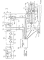
- a cutting apparatus embodying the present invention largely comprises a working table structure 11, a wheel cutter 12, a driving system 13 for the wheel cutter 2 and a controlling system 14.
- the working table structure 11 includes a stationary rigid bed 11a, a movable table 11b movable in a direction D1 with respect to the stationary rigid bed 11a and a driving mechanism 11c for moving the stationary rigid bed 11b.
- An electric motor, a reduction gear unit and a pinion/rack may form in combination the driving mechanism 11c.
- the direction D1 is perpendicular to the paper where figure 6 is illustrated and to directions D2 and D3.
- the wheel cutter 12 is supported by a retainer 12a, and is freely driven for rotation around an axis (not shown).
- the wheel cutter 12 is a sintered product of artificial diamond powder.
- the retainer 12a and, accordingly, the wheel cutter 12 are associated with the driving system 13, and are moved in the directions D2 and D3.
- the driving system 13 includes a servo-motor unit 13a, a stationary frame work 13b and a rotation-to-liner motion converting mechanism 13c.
- the stationary frame work 13b is provided over the working table structure 11, and is constituted by bracket members 13d and 13e and two guide rods 13f and 13g.
- the bracket members 13d and 13e are spaced apart from each other by a distance not shorter than the length of the movable table 11b, and the guide rods 13f and 13g extend in parallel between the bracket members 13d and 13e.
- a ball thread unit serves as the rotation-to-linear motion converting mechanism 13c.
- a male screw rod 13h, a female screw block 13i and balls (not shown) form the ball thread unit, and the male screw rod 13h is assembled with the female screw block 13i in in-phase manner.
- the balls are inserted into the spiral gap between the male screw rod 13h and the female screw block 13i, and are circulated in the spiral gap.
- the male screw rod 13h is rotatably supported by the two bracket members 13d and 13e, and is connected to the shaft of the servo-motor unit 13a by means of a suitable coupling unit 13j.
- a movable bracket 13k is fixed to the female screw block 13i, and is slidable on the guide rods 13f and 13g in the direction D2.
- the driving system 13 further includes an electric motor unit 13m and a rotation-to-linear motion converting unit 13n provided between the electric motor unit 13m and a cylinder 14t supported by the movable bracket 13k.
- the rotation-to-linear motion converting unit 13n is similar to the rotation-to-linear motion converting unit 13h/13i, and no further description is incorporated hereinbelow for avoiding repetition.
- the cylinder 14t While the electric motor unit 13m is rotating, the cylinder 14t is moved in the direction D3, and presses the cutter 12 against, or spaces it from a workpiece on the movable table 11b.
- the controlling system 14 includes a pneumatic control sub-system 14a and a controlling unit 14b, and the controlling unit 14b directly controls the driving mechanism 11c, the rotation-to-linear motion converting mechanism and the pneumatic control sub-system 14a through a data processing.
- a data processor, a program storage, a data storage and an signal interface are incorporated in the controlling unit 45b, and the data process executes instructions supplied from the program storage as will be described in detail in conjunction with a cutting operation on the ceramic plate 15.
- the pneumatic control sub-system includes a high pressure air source section 14c, a pre-treatment and adjusting section 14d, a controlling section 14e and an actuator section 14f.
- An air compressor unit 14g and a reservoir tank 14h form in combination the high pressure air source section 14c, and supplies high-pressure air to the pretreatment and adjusting section 14d.
- the air compressor unit 14g interrupts the air compressing.
- a pressure switch 14h' detects the low pressure, and instructs the air compressor unit 14g to restart the operation.
- the high-pressure air source section 14c supplies the high-pressure air between the higher limit and the lower limit to the pre-treatment and adjusting section 14d.
- the pretreatment and adjusting section 14d contains an air filter 14i, an air pressure regulator 14j and a separator 14k.
- the air filter 14i eliminates dust from the high-pressure air, and the air pressure regulator 14j keeps the air pressure constant.
- the separator 14k supplies lubricant such as lube oil into the high-pressure air for the actuator 14f and valves of the controlling section 14e.
- the controlling section 14e contains a pressure switch unit 14m, a voltage-to-air pressure converting valve unit 14n and a solenoid-operated three-port control valve unit 14o.
- the pressure switch unit 14m monitors the high-pressure air supplied from the pretreatment and adjusting unit 14d, and generates an alarm signal AL indicative of an actual air pressure lower than a critical level.
- the alarm signal AL is supplied to the controlling unit 14b.
- the voltage-to-air pressure converting valve unit 14n is responsive to a potential or voltage signal VT indicative of a target value of the high-pressure air so as to regulate the actual air pressure to the target value.
- a solenoid 14p is incorporated in the voltage-to-air pressure converting valve unit 14n, and generates electro-magnetic force in the presence of the potential signal VT.
- the electro-magnetic force is variable with the voltage level of the potential signal VT, and changes a throttle (not shown) for changing the air pressure at the outlet port thereof.
- the throttle is further controlled in such a manner as to keep the air pressure to the target value regardless of the amount of air flow.
- the potential signal VT is step-wise variable, and, accordingly, the voltage-to-air pressure converting valve unit 14n can step-wise vary the actual air pressure.
- the step of the potential variation is so narrow that the voltage-to-air pressure converting valve unit increases the air pressure as if it traces a linear line.
- the solenoid-operated three-port control valve unit 14o has an inlet port P, an outlet port A and discharge port R.
- the inlet port R is connected to the outlet port of the voltage-to-air pressure converting valve unit 14n, and the outlet port A is connected to the actuator 14f.
- the discharge port R is open through a silencer 14q to the air.
- the solenoid-operated three-port control valve unit 14o is bi-stable. Namely, a return spring 14r causes the outlet port A to be connected to the discharge port R in the absence of a change-over control signal CH supplied form the controlling unit 14b. However, when the change-over control signal CH is supplied to a solenoid 14s, the inlet port P is connected to the outlet port A, and the high-pressure air is transferred from the voltage-to-air pressure converting valve unit 14n to the actuator 14f.
- the cylinder 14t, a plunger 14u and a return spring 14v constitute the actuator 14f.
- the outlet port A is connected to the cylinder 14t, and supplies the high-pressure air to the inner chamber of the cylinder 14t.
- the plunger 14u is slidably accommodated in the inner chamber of the cylinder 14t, and the retainer 12a is connected to the leading end of the plunger 14u.
- the plunger 14u is urged into the cylinder 14t by the return spring 14v, and moves telescopically from and into the inner chamber depending upon the pressure in the inner chamber of the cylinder 14t.
- the retainer 12a is moved together with the plunger 14u in the direction D3, and the wheel cutter is pressed against, on spaced from a ceramic plate 15 mounted on the movable table 11b.
- the wheel cutter 12 supported by the retainer 12a serves as a tool, and the actuator 14t behaves as the pressing means.
- the servo-motor 13a, the stationary frame structure 13b, the rotation-to-linear motion converting unit 13c and the coupling unit 13j as a whole constitute a driving means.
- the high-pressure source section 14c, the pre-treatment and adjusting section 14d and the controlling section 14e form in combination a controlling means, and a measuring means is implemented by the controlling unit 14b as will be understood hereinbelow.
- the driving mechanism 11c aligns the wheel cutter 12 with an imaginary cutting line on the ceramic plate 15.
- the controlling unit 14b instructs the servo-motor unit 13a to move the bracket 13k to a starting point above the right end of the ceramic plate 15.
- the air compressor unit 14g has stored the high-pressure air in the reservoir tank 14h
- the controlling unit 14b does not supply the change-over control signal CH to the solenoid 14s, and the solenoid-operated three-port control valve unit 140 conducts the atmospheric pressure to the inner chamber of the cylinder 14f.
- the return spring 14v causes the plunger 14u to retract into the inner chamber, and the wheel cutter 12 is spaced from the ceramic plate.
- the controlling unit 14b minimizes the potential level of the potential signal VT, and instructs the voltage-to-air pressure converting valve unit 14n to regulate the actual air pressure to the minimum target value.
- the controlling unit 14b supplies the change-over control signal CH to the solenoid 14s, and the solenoid-operated three-port control valve unit 140 connects the inlet port P to the outlet port A as shown in figure 7.
- the high-pressure air is supplied through the solenoid-operated three-port control valve unit 14o to the inner chamber of the cylinder 14t.
- the plunger 14u extends or projects from the cylinder 14t, and presses the wheel cutter 12 against the right end of the cutting line on the ceramic plate 15 at the minimum pressure.
- the controlling unit 14b instructs the the servo-motor unit 13a to rotate the male screw rod 13h.
- the rotation-to-linear motion converting unit 13c moves the movable bracket 13k and, accordingly, the actuator 14f and the wheel cutter 12 along the cutting line toward the left end of the ceramic plate 15.
- the wheel cutter 12 cuts the ceramic plate along the cutting line, and a trail or cutting line of the wheel cutter 12 is left in the ceramic plate 15.
- the controlling unit 14b instructs the servo-motor unit 13a to stop the rotation, and the movable bracket 13k and the wheel cutter 12 terminate at the left end on the cutting line.
- the controlling unit 14b removes the change-over control signal CH from the solenoid 14s.
- the wheel cutter 12 stops the rotation, and the return spring 14r causes the outlet port A to be connected to the discharge port R.
- the high-pressure air is discharged from the inner chamber of the cylinder 14t through the solenoid-operated three-port control valve unit 14o and the silencer 14q to the atmosphere.
- the return spring 14v causes the plunger 14u to retract into the cylinder, and the wheel cutter 12 is spaced from the ceramic plate 15.
- the cutting apparatus repeats the cutting operation on ceramic plates 15.
- the data processor When the wheel cutter 12 is replaced with a new one, the data processor resets an internal register of the data storage to, zero. While the wheel cutter 12 is cutting along the cutting line, the data processor increments the total length of the cutting line, and checks the total length of the cutting line to determine the potential level of the voltage signal VT.
- the data processor executes a main routine program, and controls the driving mechanism 11c, the driving system 13 and the controlling system 14 for cutting or scribing the ceramic plate 15.
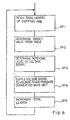
- the data processor repeats a routine shown in figure 8 during the cutting operation.
- the data processor fetches the data indicative of the total length of the cutting line stored in the internal register as by step SP1, and compares the total length of the cutting line with a table defining relation between the total length and the target value of the high-pressure air.
- the table is established in the data storage.
- the table divides the length of the cutting line into narrow ranges, and associates the narrow ranges with different target values, respectively. However, the target value is varied as if it traces a linear line as described hereinbefore.
- the data processor determines the target value through the comparison with the table as by step SP2, and instructs a signal generator to regulate the voltage signal VT to the potential level indicative of the target value as by step SP3.
- the data processor allows the signal generator to supply the voltage signal VT to the voltage-to-air pressure converting valve unit 14n as by step SP4, and increments the total length of the cutting line as by step SP5.
- the data processing unit reiterates the loop consisting of steps SP1 to SP5 until the service life of the wheel cutter 12 is expired.
- the total length of the cutting line is measured as follows.
- the data processing unit calculates the total length on the basis of the control data for the numerical control.
- the data processing unit multiplies the length of the cutting line by the number of repetition so as to determine the total length of the cutting line.
- a revolution meter such as an encoder plate is fixed to the shaft supporting the wheel cutter 12, and the number of the rotations is reported to the data processing unit.
- the data processing unit multiplies the circumference of the wheel cutter by the number of rotations so as to determine the total length of the cutting line.
- the controlling unit 14b updates the total length of the cutting line, and varies the target value of the high-pressure air.
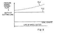
- the pressure against the ceramic plate 15 is increased together with the total length of the cutting line as indicated by plots PL4, and the depth of the cutting line is maintained constant as indicated by plots PL5 (see figure 9).
- the controlling unit 14b changes the target value for the high-pressure air, and the wheel cutter 12 is exactly controlled without an error.
- the pressure switch 14m produces the alarm signal AL, and supplies the alarm signal AL to the signal interface of the controlling unit 45b.
- the controlling unit acknowledges the emergency state, and removes the change-over control signal CH from the solenoid 14s.
- the solenoid-operated three-port control valve 14o connects the outlet port A to the discharge port R, and the high-pressure air is evacuated from the inner chamber of the cylinder 14t to the atmosphere.
- the return spring 14v causes the plunger 14u to retract into the cylinder 14t, and the wheel cutter 12 is spaced from the ceramic plate 15.
- the controlling unit 45b further instructs the servo-motor 13a to stop the rotation, and generate an alarm sign on a display (not shown).
- an electric circuit and a solenoid-operated actuator may be used instead of the pneumatic control sub-system 14a and the actuator 14f.
- the driving mechanism may rotate the movable table so as to carry out a position control in rotational coordinates.
- the wheel cutter may be replaced with a scriber, and may be rotated by a motor unit.
Landscapes
- Engineering & Computer Science (AREA)
- Chemical & Material Sciences (AREA)
- Mechanical Engineering (AREA)
- Materials Engineering (AREA)
- Organic Chemistry (AREA)
- Mining & Mineral Resources (AREA)
- Processing Of Stones Or Stones Resemblance Materials (AREA)
- Nonmetal Cutting Devices (AREA)
Claims (5)
- Schneidvorrichtung zum Schneiden einer Reihe von Werkstücken (15), die von einer stationären Struktur (11a/13b) getragen wird, die folgendes aufweist:ein Schneidwerkzeug (12), welches von der stationären Struktur (11a/13b) getragen wird, und relativ mit Bezug auf jedes der Werkstücke in Abfolge bewegbar ist;Pressenmittel (14f) zum Pressen des Schneidwerkzeuges (12) gegen jedes der Reihe von Werkstücken (15), undAntriebsmittel (13a/13b/13c) zum Vorsehen einer Relativbewegung zwischen dem Schneidwerkzeug (12) und jedem in Abfolge liegenden Werkstück der Reihe von Werkstücken zur Erzeugung von Schneidlinien in der Reihe von Werkstücken (15),
gekennzeichnet dadurch, daß sie folgendes aufweist:Meßmittel (14b) zum Messen der Gesamtlänge der Schneidlinien in der Reihe von Werkstücken (15); undSteuermittel (14b/14c/14d/14e) zum Einstellen des Druckes, mit dem das Schneidwerkzeug gegen die Abfolge von Werkstücken (15) gedrückt wird, und zwar gemäß der Gesamtlänge von Schneidlinien, wodurch die Abmessungen der Schneidlinien konstant gemacht werden. - Schneidvorrichtung nach Anspruch 1, wobei das Schneidwerkzeug ein Radschneidwerkzeug (12) ist.
- Schneidvorrichtung nach Anspruch 1, wobei die Pressenmittel (14f) einen Zylinder (14t) mit einer Luftkammer darin aufweisen, mit einem Stößel (14u), der aus dem Zylinder (14t) heraus zu fahren und dorthin hinein zu ziehen ist, und eine Rückstellfeder (14v), die den Stößel (14u) in einer Richtung zum Rückzug in den Zylinder (14t) zwingt.
- Schneidvorrichtung nach Anspruch 3, wobei die Antriebsmittel eine Motoreinheit (13a) aufweisen, eine stationäre Rahmenstruktur (13b), die über dem Werkstück (15) vorgesehen ist, einen bewegbaren Bügel (13k), der den Zylinder (14t) trägt, und der linear mit Bezug auf die stationäre Rahmenstruktur (13b) bewegbar ist, und eine Rotation-Linearbewegung-Umwandlungseinheit (13c), die zwischen dem Motor (13a) und dem bewegbaren Bügel (13k) angeschlossen ist, um den bewegbaren Bügel (13k) hin und her zu bewegen.
- Schneidvorrichtung nach Anspruch 3, wobei die Steuermittel folgendes aufweisen:eine Hochdruckluftquelle (14c) zur Erzeugung von Hochdruckluft,einen Vorbehandlungs- und Einstellabschnitt (14d) zur Erzeugung von verfügbarer Hochdruckluft aus der Hochdruckluft,eine Steuereinheit (14b) zur Erzeugung eines Spannungssignals (VT) welches einen Zielwert für die Hochdruckluft anzeigt, und zwar variabel mit der Gesamtlänge der Schneidlinien, undeinen Pneumatiksteuerventilabschnitt (14e) mit einer Spannung-Luftdruck-Umwandlungsventileinheit (14n), die auf das Spannungssignal (VT) zur Regulierung der Hochdruckluft auf den Zielwert anspricht, und die die variable Hochdruckluft, die von der Spannung-Luftdruck-Umwandlungsventileinheit geregelt wird, zu dem Zylinder (14t) liefert.
Applications Claiming Priority (3)
| Application Number | Priority Date | Filing Date | Title |
|---|---|---|---|
| JP21607494 | 1994-09-09 | ||
| JP06216074A JP3116743B2 (ja) | 1994-09-09 | 1994-09-09 | ホイールカッター方式切断装置 |
| JP216074/94 | 1994-09-09 |
Publications (3)
| Publication Number | Publication Date |
|---|---|
| EP0700877A2 EP0700877A2 (de) | 1996-03-13 |
| EP0700877A3 EP0700877A3 (de) | 1996-08-14 |
| EP0700877B1 true EP0700877B1 (de) | 2001-04-11 |
Family
ID=16682855
Family Applications (1)
| Application Number | Title | Priority Date | Filing Date |
|---|---|---|---|
| EP95114104A Expired - Lifetime EP0700877B1 (de) | 1994-09-09 | 1995-09-08 | Schneidevorrichtung mit einem Schneidewerkzeug das, in Abhängigkeit der totalen Schnittlänge, mit variablen Druck auf die nacheinanderfolgenden Werkstücke gedrückt wird |
Country Status (4)
| Country | Link |
|---|---|
| US (2) | US5860349A (de) |
| EP (1) | EP0700877B1 (de) |
| JP (1) | JP3116743B2 (de) |
| DE (1) | DE69520626T2 (de) |
Families Citing this family (26)
| Publication number | Priority date | Publication date | Assignee | Title |
|---|---|---|---|---|
| EP1090726B1 (de) * | 1999-01-11 | 2004-06-16 | Beldex Corporation | Ritzwerkzeug |
| US6386084B1 (en) * | 1999-01-28 | 2002-05-14 | Canon Kabushiki Kaisha | Method for cutting substrate |
| CN1863740B (zh) * | 2001-07-18 | 2012-04-25 | 三星钻石工业股份有限公司 | 划线头和使用该划线头的划线装置以及划线方法 |
| US20040027038A1 (en) * | 2002-08-12 | 2004-02-12 | Thermwood Corporation | System and method for cutting a furniture component to size and marking joint locations thereon |
| DE10237478B4 (de) * | 2002-08-16 | 2005-06-09 | Schott Ag | Verfahren zum Schneiden eines fortlaufenden Glasbandes bei der Herstellung von Flachglas |
| DE10313405A1 (de) * | 2003-03-25 | 2004-10-07 | Zubler Gerätebau GmbH | Dentaltechnikofen zur Herstellung von Presskeramik |
| US20050178254A1 (en) * | 2003-07-02 | 2005-08-18 | Lexmark International Inc. | Method for setting a location of an incising boundary around one or more objects |
| US7066671B2 (en) * | 2003-07-02 | 2006-06-27 | Adam Jude Ahne | Method for forming perforations in a sheet of media with a perforation system |
| US7204654B2 (en) * | 2003-07-02 | 2007-04-17 | Lexmark International, Inc. | Perforation forming mechanism for use in an imaging apparatus |
| JP4701688B2 (ja) * | 2004-11-26 | 2011-06-15 | 富士ゼロックス株式会社 | 細断処理装置、および細断処理方法 |
| GB0505139D0 (en) * | 2005-03-12 | 2005-04-20 | Pilkington Plc | Improved apparatus and methods for scoring |
| JP5023547B2 (ja) * | 2006-04-28 | 2012-09-12 | 坂東機工株式会社 | ガラス板切断方法及びガラス板切断機 |
| DE102006041208B4 (de) * | 2006-09-02 | 2014-08-07 | Leica Biosystems Nussloch Gmbh | Messgerät für ein Vibrationsmikrotom und Vibrationsmikrotom mit einem Messgerät |
| US8051681B2 (en) * | 2007-05-09 | 2011-11-08 | Corning Incorporated | Constant force scoring device and method for using same |
| DE102007023457B4 (de) * | 2007-05-19 | 2009-05-20 | Leica Biosystems Nussloch Gmbh | Verfahren zur automatischen Annäherung eines dünn zu schneidenden Präparates an das Messer eines Mikrotoms |
| US20100154613A1 (en) * | 2008-12-19 | 2010-06-24 | Multi-Color Corporation | Label that is Removable or Having a Removable Section |
| WO2011034698A2 (en) * | 2009-09-15 | 2011-03-24 | Jian-Qiang Kong | Microtome |
| JP5472235B2 (ja) * | 2011-08-12 | 2014-04-16 | 坂東機工株式会社 | ガラス板切断方法及びガラス板切断機 |
| WO2014145660A1 (en) * | 2013-03-15 | 2014-09-18 | Shaw Industries Group, Inc. | Automated hardwood texturing system and associated methods |
| CN103739192B (zh) * | 2013-11-14 | 2016-02-17 | 上海和辉光电有限公司 | 切割装置及切割方法 |
| JP2015143174A (ja) * | 2013-12-27 | 2015-08-06 | AvanStrate株式会社 | ガラス板の製造方法、シートガラスのスクライブ装置、及びガラス板の製造装置 |
| CN103896483B (zh) * | 2014-03-27 | 2016-08-17 | 深圳市华星光电技术有限公司 | 一种玻璃基板切割设备及切割方法 |
| CN105856286A (zh) * | 2016-03-31 | 2016-08-17 | 成都惠宝节能科技有限公司 | 一种基于三级管组合式稳压电源的保温板切边系统 |
| CN105856285A (zh) * | 2016-03-31 | 2016-08-17 | 成都惠宝节能科技有限公司 | 一种双极性稳压电源式保温板切边系统 |
| CN105773675A (zh) * | 2016-03-31 | 2016-07-20 | 成都惠宝节能科技有限公司 | 基于三级管组合式稳压电源的三阶滤波式保温板切边系统 |
| CN117507155A (zh) * | 2023-11-07 | 2024-02-06 | 京东方科技集团股份有限公司 | 面板切割方法、装置、电子设备及存储介质 |
Family Cites Families (20)
| Publication number | Priority date | Publication date | Assignee | Title |
|---|---|---|---|---|
| US3577636A (en) * | 1969-01-07 | 1971-05-04 | Ppg Industries Inc | Resilient cutter |
| FR2105067B1 (de) * | 1970-09-22 | 1975-04-11 | Saint Gobain | |
| US3760997A (en) * | 1971-03-26 | 1973-09-25 | Ppg Industries Inc | Glass cutting using a direct-current torque motor |
| BE797819A (fr) * | 1972-04-10 | 1973-10-05 | Ppg Industries Inc | Procede et appareil de decoupe de verre en utilisant des fissures creees en dessous de la surface et articles obtenus |
| US3756104A (en) * | 1972-06-23 | 1973-09-04 | Ppg Industries Inc | Cutting of glass |
| US3821910A (en) * | 1972-08-08 | 1974-07-02 | South Bend Controls Inc | Glass cutting mechanism |
| US3880028A (en) * | 1974-02-25 | 1975-04-29 | Ppg Industries Inc | Method and apparatus for monitoring and controlling glass cutting |
| US4057184A (en) * | 1975-09-19 | 1977-11-08 | Ppg Industries, Inc. | Method of scoring glass using a scoring wheel having an arcuate scoring surface |
| US4027562A (en) * | 1976-03-23 | 1977-06-07 | Ppg Industries, Inc. | Force applying device for scoring wheels |
| US4096773A (en) * | 1976-09-22 | 1978-06-27 | Ppg Industries, Inc. | Self-aligning apparatus for scoring fracturable material |
| DE2646062C3 (de) * | 1976-10-13 | 1979-08-09 | Vereinigte Glaswerke Gmbh, 5100 Aachen | Numerisch gesteuerte Modellschneidemaschine für Glasscheiben |
| US4170159A (en) * | 1978-01-03 | 1979-10-09 | Contraves Goerz Corporation | Linear positioning apparatus |
| US4291824A (en) * | 1978-01-26 | 1981-09-29 | Ppg Industries, Inc. | Self-aligning method for scoring fracturable material |
| US4226153A (en) * | 1979-05-17 | 1980-10-07 | The Fletcher-Terry Company | Compensating glass scoring head |
| DE3002071A1 (de) * | 1980-01-21 | 1981-07-23 | Vereinigte Glaswerke Gmbh, 5100 Aachen | Schneidkopf fuer glasschneidemaschinen |
| US4356944A (en) * | 1981-03-06 | 1982-11-02 | Bourns, Inc. | Method and apparatus for breaking prescored ceramic substrate plates |
| US4787178A (en) * | 1987-04-13 | 1988-11-29 | Creative Glassworks International, Inc. | Fluid-jet cutting apparatus |
| US5038654A (en) * | 1989-04-04 | 1991-08-13 | Ppg Industries, Inc. | Apparatus for scoring a glass sheet |
| US5054355A (en) * | 1990-03-13 | 1991-10-08 | Guardian Industries Corp. | Automatic glass cutting and positioning system |
| WO1993021119A1 (fr) * | 1992-04-16 | 1993-10-28 | Bando Kiko Co., Ltd. | Appareil pour le decoupage de plaques de verre |
-
1994
- 1994-09-09 JP JP06216074A patent/JP3116743B2/ja not_active Expired - Lifetime
-
1995
- 1995-09-08 EP EP95114104A patent/EP0700877B1/de not_active Expired - Lifetime
- 1995-09-08 DE DE69520626T patent/DE69520626T2/de not_active Expired - Lifetime
-
1997
- 1997-06-19 US US08/878,480 patent/US5860349A/en not_active Expired - Fee Related
-
1998
- 1998-11-09 US US09/188,499 patent/US6105483A/en not_active Expired - Lifetime
Also Published As
| Publication number | Publication date |
|---|---|
| DE69520626D1 (de) | 2001-05-17 |
| JPH0872051A (ja) | 1996-03-19 |
| US6105483A (en) | 2000-08-22 |
| EP0700877A3 (de) | 1996-08-14 |
| US5860349A (en) | 1999-01-19 |
| DE69520626T2 (de) | 2001-09-13 |
| EP0700877A2 (de) | 1996-03-13 |
| JP3116743B2 (ja) | 2000-12-11 |
Similar Documents
| Publication | Publication Date | Title |
|---|---|---|
| US5860349A (en) | Cutting apparatus equipped with tool variably pressed against work depending upon working distance | |
| CA2060023C (en) | Valve with adjustable valve seat | |
| US20080093094A1 (en) | Air driven spindle assembly | |
| CN102216024A (zh) | 用于借助激光束加工工件的机器 | |
| US4444540A (en) | Automation lift unit | |
| US5136774A (en) | Method of making a valve with adjustable valve seat | |
| US4193739A (en) | Device for turning the rotor of a gas turbine engine | |
| EP3723930B1 (de) | Linien-lötsystem | |
| JPH0788841B2 (ja) | プレス等の液圧動作シリンダの制御装置 | |
| CN210588422U (zh) | 一种可编程控制的准干式切削系统 | |
| US3045892A (en) | Hydraulic variable volume clearance pocket device | |
| US5595103A (en) | Hydraulic drive assembly for electrical discharge machine | |
| WO2007131346A1 (en) | Pressure controller device | |
| CA2665171A1 (en) | Low consumption pneumatic controller | |
| CN2147922Y (zh) | 万能液压滚花滚齿机 | |
| CN114670307A (zh) | 板材精修装置及封边机 | |
| CN220921992U (zh) | 一种气控浮动装置及打磨设备 | |
| JP3958242B2 (ja) | 空圧アクチュエータの計時駆動装置 | |
| EP1308635B1 (de) | Verbesserung eines Schieberventils in einem Hydraulikkreis zur Regelung der Hammerbewegung in einer Stanzmaschine | |
| US3794434A (en) | Attachment for operating tool accessories | |
| CN120662893A (zh) | 一种数控线切割机床的下压机构 | |
| KR100494996B1 (ko) | 스크류 에어 컴프레샤의 용량조절밸브 | |
| US2754712A (en) | Rotary spindle | |
| SNIT | Material Removal Rate (MRR) Study in Time Reduction Pneumatic Shaper Machine | |
| US20040166770A1 (en) | Grinding apparatus and method |
Legal Events
| Date | Code | Title | Description |
|---|---|---|---|
| PUAI | Public reference made under article 153(3) epc to a published international application that has entered the european phase |
Free format text: ORIGINAL CODE: 0009012 |
|
| AK | Designated contracting states |
Kind code of ref document: A2 Designated state(s): DE |
|
| PUAL | Search report despatched |
Free format text: ORIGINAL CODE: 0009013 |
|
| AK | Designated contracting states |
Kind code of ref document: A3 Designated state(s): DE |
|
| 17P | Request for examination filed |
Effective date: 19970213 |
|
| 17Q | First examination report despatched |
Effective date: 19990225 |
|
| GRAG | Despatch of communication of intention to grant |
Free format text: ORIGINAL CODE: EPIDOS AGRA |
|
| RTI1 | Title (correction) |
Free format text: CUTTING APPARATUS WITH A CUTTING TOOL THAT, DEPENDING ON THE TOTAL LENGTH OF THE CUTTING LINE, IS PRESSED WITH A VARYING PRESSURE AGAINST A SERIES OF SEQUENTIAL WORKPIECES |
|
| RAP1 | Party data changed (applicant data changed or rights of an application transferred) |
Owner name: YAMAHA CORPORATION |
|
| GRAG | Despatch of communication of intention to grant |
Free format text: ORIGINAL CODE: EPIDOS AGRA |
|
| GRAH | Despatch of communication of intention to grant a patent |
Free format text: ORIGINAL CODE: EPIDOS IGRA |
|
| GRAH | Despatch of communication of intention to grant a patent |
Free format text: ORIGINAL CODE: EPIDOS IGRA |
|
| GRAA | (expected) grant |
Free format text: ORIGINAL CODE: 0009210 |
|
| AK | Designated contracting states |
Kind code of ref document: B1 Designated state(s): DE |
|
| REF | Corresponds to: |
Ref document number: 69520626 Country of ref document: DE Date of ref document: 20010517 |
|
| PLBE | No opposition filed within time limit |
Free format text: ORIGINAL CODE: 0009261 |
|
| STAA | Information on the status of an ep patent application or granted ep patent |
Free format text: STATUS: NO OPPOSITION FILED WITHIN TIME LIMIT |
|
| 26N | No opposition filed | ||
| PGFP | Annual fee paid to national office [announced via postgrant information from national office to epo] |
Ref country code: DE Payment date: 20130904 Year of fee payment: 19 |
|
| REG | Reference to a national code |
Ref country code: DE Ref legal event code: R119 Ref document number: 69520626 Country of ref document: DE |
|
| REG | Reference to a national code |
Ref country code: DE Ref legal event code: R119 Ref document number: 69520626 Country of ref document: DE Effective date: 20150401 |
|
| PG25 | Lapsed in a contracting state [announced via postgrant information from national office to epo] |
Ref country code: DE Free format text: LAPSE BECAUSE OF NON-PAYMENT OF DUE FEES Effective date: 20150401 |